Transcription
Introduction to VNA Basics––PRIMER
PRIMERIntroduction to VNA BasicsThe Vector network analyzer or VNA is an important testinstrument that has helped make countless modern wirelesstechnologies possible. Today, VNAs are used in a wide rangeof RF and high frequency applications. In design applications,ContentsVector Network Analyzer Overview. 3simulations are used to accelerate time-to-market by reducingWho Needs a VNA. 4physical prototype iterations. VNAs are used to validateBasic VNA Operation. 6these design simulations. In manufacturing applications, RFKey Specifications. 6components or devices are assembled and tested based onVNA vs. Spectrum Analyzer. 8a certain set of specifications. VNAs are used to quickly andaccurately validate the performance of these RF componentsand devices.This paper discusses why VNAs are used and how they areUnderstanding S-Parameters. 9Types of Measurement Error. 11Calibration Techniques. 12unique compared to other RF test equipment. We'll defineWhat is User Calibration. 12S-Parameters, the fundamental VNA measurement, and howVNA Calibration Methods. 13best to use them when evaluating your Device-Under-Test orCalibration Standards. 14DUT. We'll review various VNA calibration techniques and showhow VNA user calibrations help achieve the best accuracypossible. Finally, we'll review typical VNA measurementsTypical VNA Measurements. 15Swept Frequency Measurements. 15such as swept frequency measurements, time domainTime Domain Measurements. 16measurements, and swept power measurements and howSwept Power Measurements. 16they're used and why they are important.Testing Multiport Components. 17Summary. 182 WWW.TEK.COM
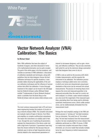
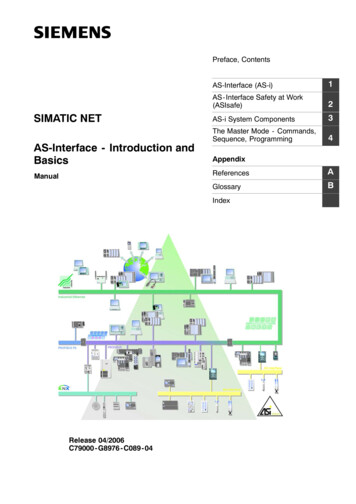
PRIMERIntroduction to VNA BasicsNot for measuringWiFi networksNot for drive testingmobile phone networksNot for computernetworks or cloudsFIGURE 1. Today there are a wide variety of networks, each with its own network analyzer. The vector network analyzer, discussed in this document, is used for adifferent kind of network and was defined long before any of these networks existed.Vector Network Analyzer OverviewTektronix 2016Today, the term “network analyzer”, is used to describe toolsfor a variety of “networks” (Figure 1). For instance, most peopletoday have a cellular or mobile phone that runs on a 3G or4G “network”. In addition, most of our homes, offices andcommercial venues all have Wi-Fi, or wireless LAN “networks”.Furthermore, many computers and servers are setup in“networks” that are all linked together to the cloud. For each ofFIGURE 2. Vector Network Analyzers or VNAs were invented in the 1950s andare actively used around the world today.these “networks”, there exists a certain network analyzer toolused to verify performance, map coverage zones and identifyproblem areas.However, the network analyzer of interest in this paper is usedfor a different kind of network and was defined long before anyof these networks existed. The first VNA was invented around1950 and was defined as an instrument that measures thenetwork parameters of electrical networks (Figure 2). In fact, itcan be said that the VNA has been used over the years to helpmake all the networks mentioned above possible. From mobilephone networks, to Wi-Fi networks, to computer networksand the to the cloud, all of the most common technologicalnetworks of today were made possible using the VNA that wasfirst invented over 60 years ago.WWW.TEK.COM 3
PRIMERIntroduction to VNA BasicsFIGURE 3. VNAs are used to make most modern technologies possible.WHO NEEDS A VNAVNAs are used to test component specifications and verifyAll wireless solutions have transmitters and receivers, and eachdesign simulations to make sure systems and their componentscontains many RF and microwave components. This includeswork properly together. R&D engineers and manufacturingnot only smartphones and WiFi networks, but also connectedtest engineers commonly use VNAs at various stages ofcars and IoT (Internet of Things) devices. Additionally, computerproduct development. Component designers need to verify thenetworks today operate at such high frequencies that they areperformance of their components such as amplifiers, filters,passing signals at RF and microwave frequencies. Figure 3antennas, cables, mixers, etc. The system designer needsshows a range of example applications that exist today with theto verify their component specs to ensure that the systemhelp of VNAs.performance they're counting on meets their subsystemand system specifications. Manufacturing lines use VNAs tomake sure that all products meet specifications before they'reshipped out for use by their customers. In some cases, VNAsare even used in field operations to verify and troubleshootdeployed RF and microwave systems.4 WWW.TEK.COM
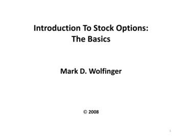
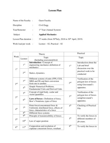
PRIMERIntroduction to VNA BasicsHow much stronger will asignal be after the amplifier?How efficient is theantenna for transitioningthe signal to/from the air?RF Front-EndUp-MixerAntennaFilterPADuplexerHow well is the transmitsignal isolated from thereceive signal?LNAVCOIFHow much signal isgetting to the antenna?How well is the signalbeing converted to a newfrequency and are anyunwanted signals beinggenerated?FilterDown-MixerHow well are unwanted signalsgoing to be filtered out?FIGURE 4. VNAs may be used to verify component, subsystem and system level performance.As an example, Figure 4 shows an RF system front end andFrom a system design point of view, how much signal goeshow different components and parts of the system are testedthrough the RF board and out of the antenna? On the receivewith a VNA. For the antenna, it is important to understand howside, how effective is the duplexer in providing isolationefficient the antenna is at transitioning the signal to and frombetween the transmit and the receive signal? All of thesethe air. As we’ll explain later, this is determined by using a VNAquestions can be answered using a VNA.to measure the return loss or VSWR of the antenna.Looking at the right side of Figure 4, the up-mixer takes theIF signal and mixes it with an oscillator (VCO) to produce theRF signal. How well is the signal being converted to a newfrequency? Are any unwanted signals being generated? Whatpower levels are the most efficient at driving the mixer? VNAsare used to answer these questions.WWW.TEK.COM 5
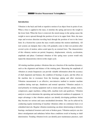
PRIMERIntroduction to VNA BasicsFIGURE 5. VNAs contain both a stimulus source and receivers to provide a very accurate closed loop for evaluating DUTs.BASIC VNA OPERATIONto a 2-port 2-path VNA, the DUT can be connected to eitherOne unique feature of a VNA is that it contains both a source,port in either direction because the instrument has theused to generate a known stimulus signal, and a set ofcapability of reversing the signal flow so that the reflections atreceivers, used to determine changes to this stimulus causedboth ports (S11 and S22), as well as the forward and reverseby the device-under-test or DUT. Figure 5 highlights the basictransmissions (S21 and S12), can be measured.operation of a VNA. For the sake of simplicity, it shows thesource coming from Port 1, but most VNAs today are multipathKEY SPECIFICATIONSinstruments and can provide the stimulus signal to either port.When determining your needs for a VNA, there are severalThe stimulus signal is injected into the DUT and the VNAspecifications, there are four top level specs which can bemeasures both the signal that's reflected from the input side,used to guide your selection process – frequency range,as well as the signal that passes through to the output side ofdynamic range, trace noise, and measurement speed.the DUT. The VNA receivers measure the resulting signals andcompare them to the known stimulus signal. The measuredresults are then processed by either an internal or external PCkey specifications to consider. While there are many VNAFrequency range is the first and most critical specification toconsider (Figure 6a). For this, it is often good to consider notand sent to a display.only your immediate needs but also potential future needs. InThere are a variety of different VNAs available on the market,some DUTs you may need to consider harmonic frequencieseach with a different number of ports and paths for whichas well. Active components, such as amplifiers, converters andthe stimulus signal flows. In the case of a 1-port VNA, themixers may need to be tested at their harmonic frequenciesDUT is connected to the input side of Figure 5 and only thewhich are 2 to 5 times operational frequency. Filters andreflected signals can be measured. For a 2-port 1-path VNA,duplexers may also need to be tested at harmonics of theirboth the reflected and transmitted signal (S11 and S21) canpassband. Although a higher frequency range may be desired,be measured, however, the DUT must be physically reversedmaximum frequency range can be a major cost driver forto measure the reverse parameters (S22 and S12). As regardsVNAs.6 WWW.TEK.COMaddition, while all DUTs have a given operational frequency, for
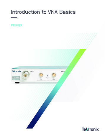
PRIMERIntroduction to VNA Basics(a) Frequency Range(b) Dynamic Range(c) Trace Noise(d) Measurement speedFIGURE 6. Top level VNA specifications can be used to quickly determine the instrument class required for your application.Dynamic range is the measurable attenuation range from maxripple in the passband of a filter. If you need a certain level ofto min for a specified frequency range (Figure 6b). Basedperformance to determine accuracy of a signal through a filter,on the desired performance of your DUT, you need to makethe added VNA trace noise contribution may be a factor.sure that the magnitude of your maximum DUT attenuationspecifications are at least three to six dB less than the VNAdynamic range specification. Most VNAs today offer verygood dynamic range ( 120 dB) which is sufficient for manyapplications. Some very high performance components mayrequire more expensive VNA solutions.Finally, one of the other specifications to consider ismeasurement speed (Figure 6d). Measurement speed is thetime it takes to perform a single sweep or measurement.This can be the most critical requirement for high volumemanufacturing applications. If you consider a component thatis used in a smartphone, there may be billions of componentsTrace noise measures how much random noise is generatedmade each year. Reducing the test time at very high volumesby the VNA and passes into the measurement. It is typicallyis critical to the success of that component. However, formeasured in milli-dB (0.001 dB). Trace noise can be a keymany R&D and low-volume production applications, the VNAfactor in determining the accuracy of certain componentsmeasurement speed is not an issue.(Figure 6c). An example may be the acceptable level ofWWW.TEK.COM 7
PRIMERIntroduction to VNA BasicsTABLE 1. Comparing a VNA and a Spectrum AnalyzerVNA VS. SPECTRUM ANALYZERtime. On the other hand, VNAs do not measure signals. TheySome design engineers may have prior experience withmeasure the inherent RF characteristics of passive or activeeither a VNA or a spectrum analyzer. Others may be newdevices.to RF testing and not familiar with either. The VNA andspectrum analyzer are two of the most commonly used RFtest instruments. But what's the difference between a networkanalyzer and a spectrum analyzer? When would you need oneor both instruments? Table 1 provides a comparison of eachinstrument.With the known stimulus and multiple receivers, the VNAcan accurately measure both the magnitude and phasecharacteristics of the DUT. This vector information is whatallows for complete device characterization. Greater accuracyand dynamic range can also be achieved using vector errorcorrection. This unique user calibration capability, which willFirst, it is important to consider what type of signals yoube discussed later, allows VNAs to factor out the influence ofneed to measure. Spectrum analyzers are the instrument ofcables, adaptors, and fixtures.choice when measuring digitally modulated signals. If thegoal is to measure, for example, the performance of Wi-Fiand LTE signals, only a spectrum analyzer can perform thesemeasurements.Some spectrum analyzers offer built-in tracking generators(SA w/TG), thus giving them much of the same capabilities asa VNA. And fundamentally speaking, a VNA works much thesame way that an SA w/ TG does. However, the key differenceAs previously mentioned, a VNA contains both source(s) andbetween the two instrument solutions is the VNA's ability toreceivers. This gives it the capability to use a known stimulusmeasure ratioed measurements using multiple receivers. Theto excite the DUT, and multiple receivers to measure itsSA w/TG does a good job for 1-port reflection measurementsresponse. VNAs can have multiple channels and ports whichand can perform error correction as well. However, forallow its receivers to measure the inputs and outputs of DUTstransmission measurements made with the SA w/TG,simultaneously.measurements can be made but not with the accuracy of theVNA. Much of this, as we’ll discuss later, is because full 2-portSpectrum analyzers are typically used to measure unknownerror correction is only possible on the VNA. On top of this, thesignals, which may be over the air via an antenna or themajority of SA w/TGs do not display phase data, which is vitaloutput of a component. They also tend to be single channelin many RF test applications.instruments, able to measure only one output from a DUT at a8 WWW.TEK.COM
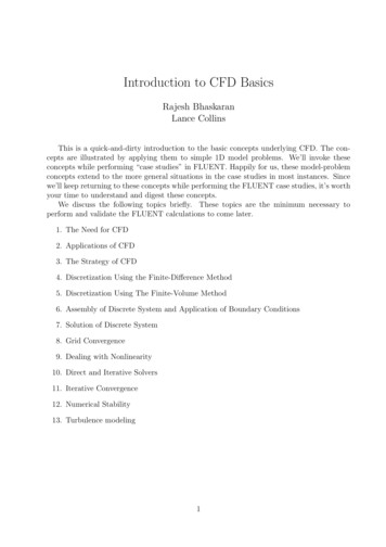
PRIMERIntroduction to VNA BasicsFIGURE 7. Understanding S-parameters.Understanding S-ParametersSince it is generally difficult to measure current or voltage athigh frequencies, scattering parameters or S-parameters aremeasured instead. They are used to characterize the electricalproperties or performance of an RF component or network ofcomponents, and are related to familiar measurements suchas gain, loss, and reflection coefficient. To understand how touse a VNA to characterize a DUT, it’s important to understandthe basics of S-parameters. Figure 7 walks through a simpleprocess of explaining S-parameters.WWW.TEK.COM 9
PRIMERIntroduction to VNA BasicsIf we start with the Outside View, a VNA typically has two orIt’s important to note that since the VNA is a bidirectionalmore ports that simply connect to the DUT - either directly orinstrument, Port 2 could also be where the known stimulus iswith the use of cables and adaptors. These ports are labeled,emitted (in that case a2), and the measurement process is thein this case, Port 1 and Port 2.same going in the reverse direction.Next, let’s consider the Inside View. The common practiceSo now that we know more about how a VNA operates, let'sused to evaluate the behavior of a multi-port network is to usetranslate the Inside View into the S-parameter Theory View.incident waves as excitations at each port and to measure theBy using a (incident) and b (reflective) waves a linear networkresulting exiting waves that are either reflected from the portor DUT can be characterized by a set of equations describingwhere power is applied or transmitted through the device tothe reflected waves from each port in terms of the incidentthe remaining ports. Generally speaking, the waves enteringwaves at all of the ports. The constants that characterize thea network or DUT are called incident waves, and the wavesnetwork under these conditions are called S-parameters.exiting a network or DUT are called reflected waves, althougheach may be composed of a combination of reflections andIn the Forward case, depicted in Figure 7, Port 1 is transmittingtransmissions from other ports.the a1 signal and a matched load is applied to Port 2, resultingThe incident waves are designated as an and the reflectedthe reflection coefficient at Port 1, or ratio of b1 over a1. S21 iswaves are designated as bn where n is the port number. Both athe forward transmission coefficient through the DUT and isand b waves are phasors, having both magnitude and phase atthe ratio of b2 over a1.the specified terminals of the network port.in zero signal reflection at the load (a2 0). S11 corresponds toIn the Reverse case, Port 2 is transmitting the a2 signal and aBehind each of the two VNA port connectors is a directionalmatched load is applied to Port 1 (a1 0). S22 corresponds tocoupler (green boxes in Figure 7). These directional couplersthe reflection coefficient at Port 2, or ratio of b2 over a2. S12 ispass the known stimulus signal into either side of the DUTthe reverse transmission coefficient through the DUT and is the(either a1 or a2).ratio of b1 over a2.First, a portion of the stimulus signal is taken as a referenceNote that in the S-parameter nomenclature, Syx, the secondsignal. S-parameters are defined as ratios of signals comingnumber (x) represents the originating port, while the firstfrom various ports relative to this reference. At the same time,number is the destination port (y). Theoretically speaking,some of the stimulus signal is reflected as it enters the DUTS-parameter theory can be applied to networks with an(b1). The portion of the input signal that is reflected is measuredinfinite number of ports. For example, a 4-port VNA wouldwith a receiver connected to Port 1 inside the VNA. The portionhave 16 S-parameters: from S11, S12, S13, S14, S21 . S44.of the input signal that enters the DUT generally experiencesThese S-parameters follow the same theory and are ratiochanges in magnitude and phase as it passes through. Themeasurements between each of the specified ports.portion that is emitted from port 2 is measured by the VNAreceiver on Port 2 (b2).10 WWW.TEK.COM
PRIMERIntroduction to VNA BasicsFIGURE 8. Types of VNA measurement error.TYPES OF MEASUREMENT ERRORThe second source of measurement error is caused byBefore you can make any measurements with the VNA,random error. This is error caused by noise emitted from theyou must calibrate it to reduce errors that can affect thetest equipment or test setup that varies with time. This errormeasurement. An understanding of measurement error isquantity is important because it will remain in the measureduseful before proceeding to calibrate a VNA because not allresult even after a user calibration has been performed, anderrors can be minimized this way.it determines the degree of accuracy that can be achieved inyour measurement. Trace noise, which was discussed earlier, isThere are three main types of measurement error (Figurean example of random error.8). The types of measurement error include systematicerrors, random errors, and drift errors. Systematic errors areA third source of error is drift error, which relates toimperfections in the test equipment or in the test setup and aremeasurement drift over time. These are variances that occurtypically predictable. Some examples include output powerin test equipment and in the test setup after a user calibrationvariations or ripples in the VNA receiver’s frequency responseis performed. Examples are temperature fluctuations,across its frequency range. Equally important is the power losshumidity fluctuations and
Introduction to VNA Basics PIME Vector Network Analyzer Overview Today, the term “network analyzer”, is used to describe tools for a variety of “networks” (Figure 1). For instance, most people today have a cellular or mobile phone