Transcription
Vibration Measurement Techniques: BasicsIntroduction:Vibration is the back and forth or repetitive motion of an object from its point of rest.When a force is applied to the mass, it stretches the spring and moves the weight tothe lower limit. When the force is removed, the stored energy in the spring causes theweight to move upward through the position of rest to its upper limit. Here, the massstops and reverses direction traveling back through the position of rest to the lowerlimit. In a friction-free system the mass would continue this motion indefinitely. Allreal systems are damped, that is they will gradually come to their rest position afterseveral cycles of motion, unless acted upon by an external force. The characteristicsof this vibratory motion are period, frequency, displacement, velocity, acceleration,amplitude and phase. Continued vibration of this spring mass system would onlyrepeat the characteristics shown in this single cycle.All rotating machines produce vibrations that are a function of the machine dynamics,such as the alignment and balance of the rotating parts. Measuring the amplitude ofvibration at certain frequencies can provide valuable information about the accuracyof shaft alignment and balance, the condition of bearings or gears, and the effect onthe machine due to resonance from the housings, piping and other structures.Vibration measurement is an effective, non-intrusive method to monitor machinecondition during start-ups, shutdowns and normal operation. Vibration analysis isused primarily on rotating equipment such as steam and gas turbines, pumps, motors,compressors, paper machines, rolling mills, machine tools and gearboxes. Vibrationanalysis is used to determine the operating and mechanical condition of equipment. Amajor advantage is that vibration analysis can identify developing problems beforethey become too serious and cause unscheduled downtime. This can be achieved byconducting regular monitoring of machine vibrations either on continuous basis or atscheduled intervals. Regular vibration monitoring can detect deteriorating or defectivebearings, mechanical looseness and worn or broken gears. Vibration analysis can alsodetect misalignment and unbalance before these conditions result in bearing or shaftdeterioration. Trending vibration levels can identify poor maintenance practices, such
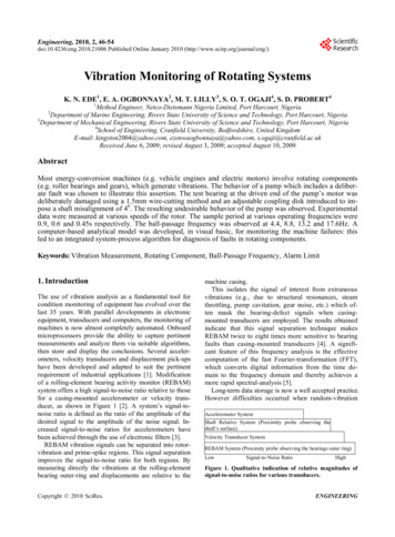
as improper bearing installation and replacement, inaccurate shaft alignment orimprecise rotor balancing.Basic Characteristics of Vibrations:Modern vibration monitoring has its genesis in the mid-1950s with the developmentand application of basic vibration sensors, which are the heart of moderncomputerized condition monitoring systems. Figure 9.1 shows the traditionalfundamental use of vibration monitoring in rotating machinery, i.e., to providewarning of gradually approached or suddenly encountered excessively high vibrationlevels that could potentially damage the machinery. Trending a machine’s vibrationlevels over an extended period of time can potentially provide early warning ofimpending excessive vibration levels and/or other problems and thus provide plantoperators with valuable information for critical decision making to schedule a timelyshutdown of a problem machine for corrective action, e.g., rebalancing the rotor. Forevaluating the machine vibrations, it is usually desirable to express frequency in termsof cycles per minute, since we measure the rotational speed of machinery inrevolutions per minute. This allows examination of the vibration frequency in termsof multiples of the rotational speed. Rotational speed is also known as thefundamental frequency and the multiples of the fundamentals frequencies are knownas its higher harmonics or super harmonics.2Vibration Amplitude (m/s )Trip levelAlarm levelSuddenincreaseTimeFig. 9.1 Vibration signature as Indicator
There are three main parameters are measured to evaluate the vibration characteristicsof any dynamic system as displacement, velocity and acceleration. The peak-to-peakdistance is measured from the upper limit to the lower limit, measured in mm tomicron level. The velocity of a vibrating object is continually changing. At the upperand lower limits, the object stops and reverses its direction of travel, thus its velocityat these two points is zero.While passing through the neutral or position of rest, the velocity is at its maximum.Since, the velocity is continually changing with respect to time, the peak or maximumvelocity is always measured and commonly expressed in mm-per-second peak. Whenexpressing the vibration characteristic in terms of velocity, both the displacement andfrequency are considered. Since, the vibrating object must reverse course at the peakdisplacements, this is where the maximum acceleration occurs. Like velocity,acceleration is constantly changing, and the peak acceleration is usually measured.Displacement measurements can be important, especially in low frequency vibrationson machines that have brittle components. That is, the stress that is applied issufficient to snap the component. Many machines have cast iron frames or cases thatare relatively brittle and are subject to failure from a single large stress. Accelerationmeasurements are also important in that they directly measure force. Excessive forcecan lead to improper lubrication in journal bearings, and result in failure. Thedynamic force created by the vibration of a rotating member can directly causebearing failure. Generally a machine can withstand up to eight times its designedstatic load before bearing failure occurs. However, overloads as little as 10% cancause damage over an extended period of time. Although this seems insignificant, itcan be shown that small unbalances can easily create sufficient dynamic forces tooverload the bearings.The International Standards Organization (ISO), who establishes internationallyacceptable units for measurement of machinery vibration, suggested the velocity –root mean square (rms) as the standard unit of measurement. This was decided in anattempt to derive criteria that would determine an effective value for the varyingfunction of velocity. Velocity – rms tends to provide the energy content in thevibration signal, whereas the velocity peak correlated better with the intensity ofvibration. Higher velocity – rms is generally more damaging than a similar magnitude
of velocity peak. The crest factor of a waveform is the ratio of the peak value of thewaveform to the rms value of the waveform. It is also sometimes called the ‘peak-torms ratio’. The crest factor of a sine wave is 1.414, i.e. the peak value is 1.414 timesthe rms value. The crest factor is one of the important features that can be used totrend machine condition. In discussing vibration velocity, it was pointed out that thevelocity of the mass approaches zero at extreme limits of travel. Each time it comes toa stop at the limit of travel, it must accelerate to increase velocity to travel to theopposite limit. Acceleration is defined as the rate of change in velocity. Referring tothe spring-mass body, acceleration of the mass is at a maximum at the extreme limitof travel where velocity of the mass is zero. As the velocity approaches a maximumvalue, the acceleration drops to zero and again continues to rise to its maximum valueat the other extreme limit of travel.Significance of Dynamic parametersThe displacement, velocity and acceleration characteristics of vibration are measuredto determine the severity of the vibration and these are often referred to as the‘amplitude’ of the vibration. In terms of the operation of the machine, the vibrationamplitude is the first indicator to indicate how good or bad the condition of themachine may be. Generally, greater vibration amplitudes correspond to higher levelsof machinery defects. The relationship between acceleration, velocity anddisplacement with respect to vibration amplitude and machinery health redefines themeasurement and data analysis techniques that should be used. Motion below 10 Hz(600 cpm) produces very little vibration in terms of acceleration, moderate vibrationin terms of velocity and relatively large vibrations in terms of displacement. Hence,displacement is used in this range. In the high frequency range, acceleration valuesyield more significant values than velocity or displacement. Hence, for frequenciesover 1000 Hz (60 kcpm) or 1500 Hz (90 kcpm), the preferred measurement unit forvibration is acceleration. It is generally accepted that between 10 Hz (600 cpm) and1000 Hz (60 kcpm) velocity gives a good indication of the severity of vibration, andabove 1000 Hz (60 kcpm), acceleration is the only good indicator. Since, the majorityof general rotating machinery (and their defects) operates in the 10–1000 Hz range,velocity is commonly used for vibration measurement and analysis. In recent time,there is a concerted effort to utilize vibration monitoring in an extended role, mainly
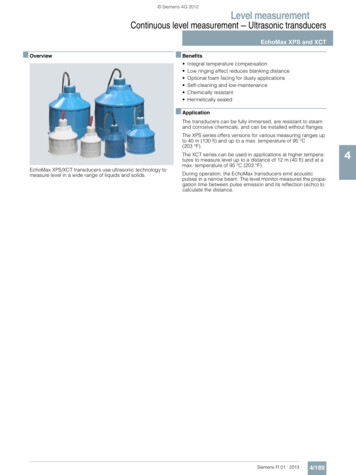
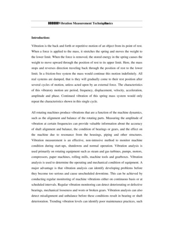
in what is now commonly called predictive maintenance, which is an extension and/orreplacement of traditional preventive maintenance. [Scheffer & Girdher]An additional benefit of a model-based diagnostic approach is the ability to combinemeasured vibration signals with vibration computer model outputs to make real-timedeterminations of rotor vibration signals at locations where no sensors are installed.Typically, vibration sensors are installed at or near the bearings where sensor accessto the rotor and survivability of sensors dictate. However, midspan locations betweenthe bearings are where operators would most like to measure vibration levels butcannot because of inaccessibility and the hostile environment for vibration sensors.Thus, the model-based approach provides “virtual sensors” at inaccessible rotorlocations.Measured vibration using sensors:The nature of sound and vibrations to be measured can vary widely. Sound can be“noisy” (roar or hiss-like), like that from a heavily trafficked highway, whilevibrations of a machine are often dominated by the rotational frequency and itsmultiples. A machine under constant loading gives off a stationary noise, while thenoise at an airport tends to be intermittent. Moreover, the purpose of measurementsvaries. The commonly monitored vibration signals are displacement, velocity, andacceleration. The basic operational principles of each of these are presented in thissection. The measurement systems that are marketed today are primarily digital, i.e.,sound pressure and vibrations are converted into digital values for later treatment inmore or less advanced signal processors. While digital technology offers ever moresophisticated possibilities, measurement systems are nevertheless often adapted to beable to compare measurement results with those obtained in the past using analogtechnology. Digital measurement systems have a more complicated structure thananalog ones.
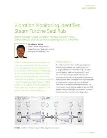
S o u n d o r v ib r a tio n s ig n a lT ra n sd u c e rE le c tr ic a l s ig n a lS ig n a l c o n d itio n in gS ig n a lIm p e d a n c em a tc h in gA c c e le r o m e te rT im eA m p lif ic a tio nM ic r o p h o n eA n a lo g f ilte rA n a lo g - d ig ita l c o n v e r s io nA m p lif ic a tio nS ig n a lF r e q u e n c y a n a ly s isD ig ita l1f ilte r in gF a s t F o u r ie rF re q u e n c yT im eT ra n sfo rmL o w p a s s f ilte r in gM e a s u r e m e n t d a tap r o c e s s in gG ra p hA m p litu d eE x a m p le :A v e r a g in gR M S a m p litu d edAe-ter m- ,inCa-tio, Bw enig h tin gF re q u e n c yFig. 9.2 Flow chart of a digital, single-channel measurement system [1]The types of transducers that are most commonly used in vibroacoustics aremicrophones to measure sound pressure, accelerometers to measure accelerations ofsolid structures, and force transducers to measure forces on solid structures. Theprinciples behind force transducers are not described here, but are very similar tothose for accelerometers.A number of characteristics are common to all types of transducers:Sensitivity:Indicates the ratio of electrical output to mechanical input. Example:A microphone’s sensitivity is given in mV/Pa.Frequency band:Indicates the upper and lower frequency limits, between whichthe transducer sensitivity varies within a given (small) tolerancerange.
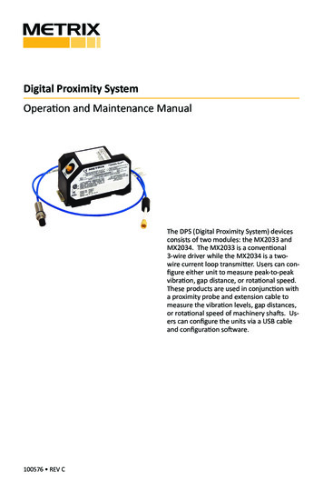
Dynamic range:Indicates the upper and lower amplitude limits between whichthe transducer sensitivity varies within a given (small) tolerancerange. The dynamic range is commonly given in dB with respect to areference value. The lower dynamic boundary is often determined bythe transducer’s electrical noise, and the upper boundary by when thetransducer is loaded beyond its mechanical linear region.a. AccelerometerAn accelerometer is composed of an internal mass compressed in contact with arelatively stiff force-measuring load cell (usually a piezoelectric crystal) by arelatively soft preload spring. For an accelerometer, the system damping is anegligible effect and thus for explanation purposes the damping is assumed here to bezero.Fig. 9.3 Uni-axial accelerometerFig. 9.4 FBD for force balance
The equation of motion then becomes,(9.1)The accelerometer load cell is usually a piezoelectric crystal and thus registers onlycompressive loads, necessitating a preload spring to keep it in compression. However,the piezoelectric crystal is inherently quite stiff in comparison to the preload spring.Therefore, the load cell essentially registers “all” the dynamic force required toaccelerate the internal mass.b. Velocity Transducers:The velocity pickup is a very popular transducer or sensor for monitoring thevibration of rotating machinery. This type of vibration transducer installs easily onmachines, and generally costs less than other sensors. For these two reasons, this typeof transducer is ideal for general purpose machine applications. Velocity pickups havebeen used as vibration transducers on rotating machines for a very long time, and theyare still util
Vibration Measurement Techniques: Basics Introduction: Vibration is the back and forth or repetitive motion of an object from its point of rest. When a force is applied to the mass, it stretches the spring and moves the weight to the lower limit. When the force is removed, the