Transcription
Crosby Valve Inc. CrosbyPressure Relief ValveEngineering HandbookCOV/CON.PM61Technical Document No. TP-V300Effective: May 1997An FMC Corporation subsidiaryTable of Contents9/22/97, 7:56 AM
Notes:COV/CON.PM629/22/97, 7:56 AM
CROSBY Pressure Relief ValveENGINEERING HANDBOOKclick on chapter for quick accessCONTENTSChapter 1Introduction to Crosby Engineering HandbookChapter 2Fundamentals of Pressure Relief Valve DesignChapter 3TerminologyChapter 4Codes and Standards - SummaryChapter 5Valve Sizing and Selection - U.S.C.S.* UnitsChapter 6Valve Sizing and Selection - Metric UnitsChapter 7Engineering Support InformationAppendixASME Section VIII, Division 1, 1992 Edition ExerptsOtherInformationOrdering InformationPressure Relief Valve Specification SheetWarning: The information contained in this handbook is for informational purposes only.See also Crosby's computer sizing program, CROSBY-SIZE. The actual selection of valvesand valve products is dependent upon numerous factors and should be made only afterconsultation with applicable Crosby personnel. Crosby assumes no responsibility for theactual selection of such products and hereby expressly disclaims liability for any and allclaims and damages which may result from the use or application of this information or fromany consultation with Crosby personnel.*United States Customary SystemCOV/CON.PM639/22/97, 7:57 AM
Crosby Engineering HandbookTechnical Publication No. TP-V300Chapter IHOMEIntroductionThe Crosby Pressure Relief Valve Engineering Handbook contains important technical information relatingto pressure relief valves.The primary purpose of a pressure relief valve is protection of life and property by venting fluid from anoverpressurized vessel. Information contained in thishandbook applies to the overpressure protection ofpressure vessels, lines and systems.Reference is made to the ASME Boiler and PressureVessel Code, Section VIII, Pressure Vessels. Theinformation in this handbook is NOT to be used forthe application of overpressure protection to powerboilers and nuclear power plant components whichare addressed in the ASME Boiler and PressureVessel Code, Section I, Power Boilers, and SectionIII, Nuclear Power Plant Components, respectively.Proper sizing, selection, manufacture, assembly, test,installation and maintenance of a pressure relief valveare all critical to obtaining maximum protection.This handbook has been designed to provide a serviceto Crosby’s customers by presenting reference data andtechnical recommendations based on our many years ofexperience in sizing, selecting, testing, installing andoperating pressure relief valves. Sufficient data issupplied so to properly size and select Crosby pressurerelief valves for specific applications. Information covering terminology, standards, codes, basic design, sizing and selection information, including examples, arepresented in an easy to use format.Some of the material in this handbook is reprinted orexcerpted from publications developed by associationsor committees in which Crosby has participated. Theinformation contained in the manual is offered as aguide. Those who use the information are reminded ofthe limitations of such a publication and that there is nosubstitute for qualified engineering analysis.Crosby pressure relief valves are manufactured in accordance with a controlled Quality Assurance Programwhich meets or exceeds ASME Code Quality ControlProgram requirements. Capacities are certified by theNational Board of Boiler and Pressure Vessel Inspectors. These features are assured by the presence of anASME Code Symbol Stamp and the letters NB on eachvalve nameplate. Crosby's valves are designed, manufactured and tested in accordance with a quality management system approved to the International Standard Organization's ISO 9000 Quality Standard Seriesrequirements. With proper sizing and selection, theuser can thus be assured that Crosby products are ofthe highest quality and technical standards in the worldof pressure relief technology.When in doubt as to the proper application of anyparticular data, the user is advised to contact the nearest Crosby Regional Office or Representative. Crosbyhas a large staff of highly trained people strategicallylocated throughout the world who should be contactedwhen a question arises. Refer to Crosby's WorldwideDirectory for an up-to-date contact listing.Crosby's Computer Aided ValveSizing Program - "CROSBY-SIZE"Crosby has designed a computer sizing program,CROSBY-SIZE, to provide maximum service to our customers by presenting recommendations based onCrosby's many years of experience. Use of this programallows an accurate determination of such parameters asorifice size, maximum flow and predicted sound level.The program is a powerful tool, yet easy to use. Its manyfeatures include quick and accurate calculations, userselected units, selection of valve size and style, valvedata storage, printed reports, specification sheets anddimensional drawings.1-1CHAPONE.PM619/22/97, 7:41 AM
Chapter 1IntroductionCrosby Engineering HandbookProgram control via pop-up windows, function keys,extensive on-line help facilities, easy to read formattedscreens, immediate flagging of errors, easy editing ofdisplayed inputs and other features combine to makethe program easy to understand and operate.It is assumed that the user of CROSBY-SIZE has a basicunderstanding of relief valve sizing calculations. Theuser is responsible for correct determination of serviceconditions and the suitability of this program for aspecific application.CROSBY-SIZE and Crosby's Engineering Handbookare useful tools in sizing pressure relief valves. Shouldadditional clarification be required, contact Crosby.1-2CHAPONE.PM629/22/97, 7:41 AM
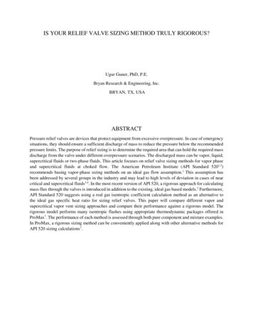
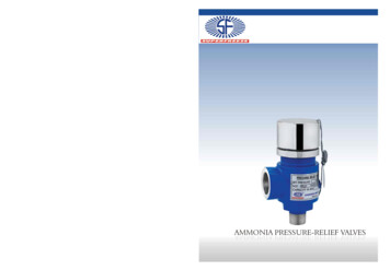
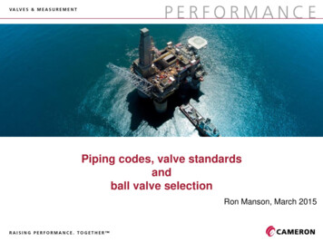
Crosby Engineering HandbookTechnical Publication No. TP-V300Chapter 2HOMEDesign FundamentalsIntroductionA pressure relief valve is a safety device designed toprotect a pressurized vessel or system during an overpressure event. An overpressure event refers to anycondition which would cause pressure in a vessel orsystem to increase beyond the specified design pressure or maximum allowable working pressure (MAWP).media. They must also be designed to operate in aconsistently smooth and stable manner on a variety offluids and fluid phases. These design parameters leadto the wide array of Crosby products available in themarket today and provide the challenge for future product development.Spring Loaded DesignSince pressure relief valves are safety devices, there aremany Codes and Standards written to control theirdesign and application. The purpose of this discussion isto familiarize you with the various parameters involved inthe design of a pressure relief valve and provide a briefintroduction to some of the Codes and Standards whichgovern the design and use of pressure relief valves.Excerpts of various applicable Codes and Standards areincluded in other sections of this handbook.Many electronic, pneumatic and hydraulic systems existtoday to control fluid system variables, such as pressure,temperature and flow. Each of these systems requiresa power source of some type, such as electricity orcompressed air in order to operate. A pressure reliefvalve must be capable of operating at all times, especially during a period of power failure when systemcontrols are nonfunctional. The sole source of power forthe pressure relief valve, therefore, is the process fluid.The basic spring loaded pressure relief valve has beendeveloped to meet the need for a simple, reliable, systemactuated device to provide overpressure protection. Figure F2-1 shows the construction of a spring loadedpressure relief valve. The valve consists of a valve inletor nozzle mounted on the pressurized system, a discheld against the nozzle to prevent flow under normalsystem operating conditions, a spring to hold the discclosed, and a body/bonnet to contain the operatingelements. The spring load is adjustable to vary thepressure at which the valve will open.Once a condition occurs that causes the pressure in asystem or vessel to increase to a dangerous level, thepressure relief valve may be the only device remaining toprevent a catastrophic failure. Since reliability is directlyrelated to the complexity of the device, it is important thatthe design of the pressure relief valve be as simple aspossible.The pressure relief valve must open at a predeterminedset pressure, flow a rated capacity at a specified overpressure, and close when the system pressure hasreturned to a safe level. Pressure relief valves must bedesigned with materials compatible with many processfluids from simple air and water to the most corrosiveCrosby Style JOS Spring LoadedPressure Relief ValveFigure F2-12-1CHAPTWO.PM619/22/97, 7:46 AM
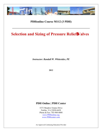
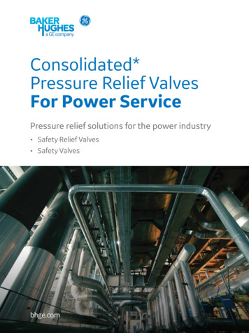
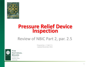
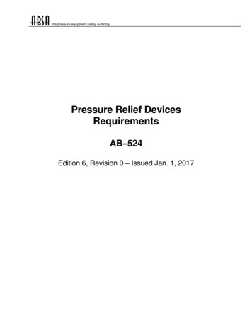
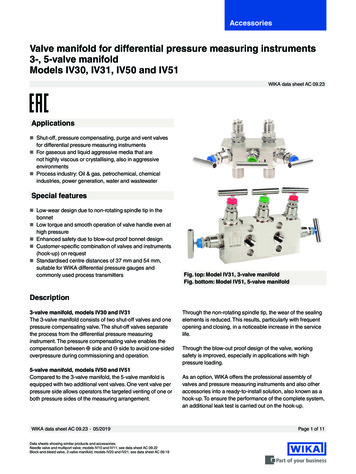
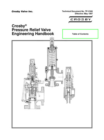
Chapter 2DesignFundamentalsCrosby Engineering HandbookFigure F2-2 is a simple sketch showing the disc held inthe closed position by the spring. When system pressurereaches the desired opening pressure, the force ofpressure acting over Area A1 equals the force of thespring, and the disc will lift and allow fluid to flow outthrough the valve. When pressure in the system returnsto a safe level, the valve will return to the closed position.When a pressure relief valve begins to lift, the springforce increases. Thus system pressure must increase iflift is to continue. For this reason pressure relief valvesare allowed an overpressure allowance to reach full lift.This allowable overpressure is generally 10% for valveson unfired systems. This margin is relatively small andsome means must be provided to assist in the lift effort.Crosby Style JOS Pressure Relief Valve TrimFigure F2-3Trim Areas DiagramFigure F2-2Most pressure relief valves, therefore, have a secondarycontrol chamber or huddling chamber to enhance lift. Atypical configuration is shown in Figure F2-3. As the discbegins to lift, fluid enters the control chamber exposinga larger area A2 of the disc (Figure F2-2) to systempressure. This causes an incremental change in forcewhich overcompensates for the increase in spring forceand causes the valve to open at a rapid rate. At the sametime, the direction of the fluid flow is reversed and themomentum effect resulting from the change in flowdirection further enhances lift. These effects combine toallow the valve to achieve maximum lift and maximumflow within the allowable overpressure limits. Because ofthe larger disc area A2 (Figure F2-2) exposed to systempressure after the valve achieves lift, the valve will notclose until system pressure has been reduced to somelevel below the set pressure. The design of the controlchamber determines where the closing point will occur.The design of the control or huddling chamber involvesa series of design tradeoffs. If the design maximizes lifteffort then blowdown will be long. If the design objectiveis to minimize blowdown, then the lift effort will bediminished. Many pressure relief valves are, therefore,equipped with a nozzle ring which can be adjusted tovary the geometry of the control chamber to meet aparticular system operating requirement (Figures F2-2and F2-3).Liquid Trim DesignsFor liquid applications, Crosby offers a unique, patentedliquid trim design designated as Style JLT-JOS or JLTJBS. See Figure F2-4 showing liquid trim available inmetal or soft seated valves. These designs providestable non-chattering valve performance and highcapacity at 10% overpressure.The difference between the set pressure and the closingpoint pressure is called blowdown and is usually expressed as a percentage of set pressure.Metal SeatO-Ring Soft SeatCrosby Styles JLT-JOS and JLT-JBSFigure F2-42-2CHAPTWO.PM629/22/97, 7:46 AM
Chapter 2DesignFundamentalsCrosby Engineering HandbookMaterials of ConstructionCompatibility with the process fluid is achieved by careful selection of materials of construction. Materials mustbe chosen with sufficient strength to withstand the pressure and temperature of the system fluid. Materials mustalso resist chemical attack by the process fluid and thelocal environment to ensure valve function is not impaired over long periods of exposure. Bearing properties are carefully evaluated for parts with guiding surfaces. The ability to achieve a fine finish on the seatingsurfaces of the disc and nozzle is required for tight shutoff. Rates of expansion caused by temperature ofmating parts is another design factor.Back Pressure ConsiderationsPressure relief valves on clean non-toxic, non-corrosivesystems may be vented directly to atmosphere. Pressure relief valves on corrosive, toxic or valuable recoverable fluids are vented into closed systems. Valves thatvent to the atmosphere, either directly or through shortvent stacks, are not subjected to elevated back pressureconditions. For valves installed in a closed system, orwhen a long vent pipe is used, there is a possibility ofdeveloping high back pressure. The back pressure on apressure relief valve must always be evaluated and itseffect on valve performance and relieving capacity mustbe considered.A review of the force balance on the disc (Figure F2-2 onpage 2-2) shows that the force of fluid pressure acting onthe inlet side of the disc will be balanced by the force ofthe spring plus whatever pressure exists on the outletside of the valve. If pressure in the valve outlet varieswhile the valve is closed, the valve set pressure willchange. If back pressure varies while the valve is openand flowing, valve lift and flow rate through the valve canbe affected. Care must be taken in the design andapplication of pressure relief valves to compensate forthese variations.Conventional ValvesBack pressure which may occur in the downstreamsystem while the valve is closed is called superimposedback pressure. This back pressure may be a result of thevalve outlet being connected to a normally pressurizedsystem or may be caused by other pressure relief valvesventing into a common header. Compensation for superimposed back pressure w
Chapter 5 Valve Sizing and Selection U.S.C.S. Units. The following formula is used for sizing valves for steam service at 10% overpressure. This formula is based on the empirical Napier formula for steam flow. Correction factors are included to account for the effects of superheat, back pressure and subcritical flow.