Transcription
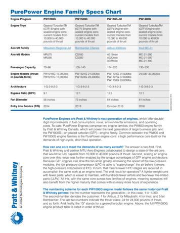
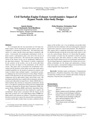
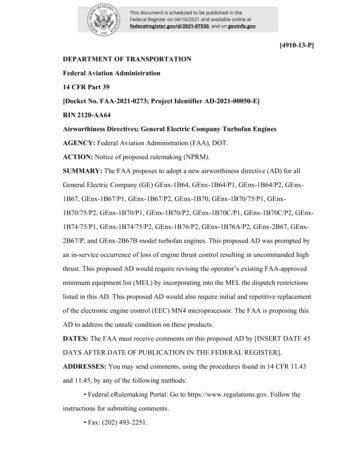
Technical ArticlesDevelopment of PW1100G-JM Turbofan EngineSATO Atsushi : Deputy General Manager, PW1000G-JM Department, Japanese AeroEngines CorporationIMAMURA Mitsuo : General Manager, PW1000G-JM Department, Japanese Aero EnginesCorporationFUJIMURA Tetsuji : General Manager, Engineering Department, Civil Aero-Engine Division,Aero-Engine & Space OperationsThe PW1100G-JM is one of the next-generation turbofan engines selected to power the Airbus A320neo(New Engine Option). IHI participated in the PW1100G-JM program as a member company of the JapaneseAero Engines Corporation (JAEC). The PW1100G-JM adopts the Geared Turbo Fan (GTF) system and deliversimprovements in fuel efficiency, emissions, and noise by applying state-of-the-art composite materials andcomponent technologies. This paper presents an overview of the PW1100G-JM.1. IntroductionAirbus (France: Airbus SAS) is currently developing theA320neo (New Engine Option), and is aiming to achievea 15% higher fuel efficiency, a double-digit reduction inNOx emissions, and a 50% reduction in airframe noise byreplacing the engine of the A320 currently in service withthat of a state-of-the-art design and keeping the airframeconverting cost to a minimum. Figure 1 illustrates anext-generation narrow-body commercial aircraft AirbusA320neo. The PW1100G-JM (Fig. 2) has been selectedas one of the engines to be installed on the A320neo.Development of this engine began as an internationalcollaborative project under IAE, LLC, a consortium ofPratt & Whitney (P&W, USA), the Japanese Aero EnginesCorporation (JAEC), and MTU Aero Engines HoldingsAG (MTU, Germany). IHI participated in the projectas a member company of JAEC. In addition, JAEC isdeveloping this engine with financial assistance from theInternational Aircraft Development Fund (IADF).The PW1100G-JM adopts a Geared Turbo Fan (GTF)system with an advanced gear system, and the bypassratio has been increased to approximately 12 to achievehigh propulsion efficiency. Furthermore, state-of-the-artcomposite materials and component technologies havebeen combined to deliver improvements in fuel efficiency,emissions, and noise.This paper presents an overview of the PW1100G-JMdevelopment program, as well as the engineering featuresof the components being developed by IHI.2. Overview of PW1100G-JM development(Image credit : Airbus)Fig. 1 Airbus A320neo aircraft(Image credit : P&W)Fig. 2 PW1100G-JM cutaway view (1)2.1 Development historyThe A320neo family of narrow-body aircraft beingdeveloped by Airbus provides great improvements in costeffectiveness and environmental friendliness by replacingthe engines of the existing A320 aircraft family (theV2500 and the CFM56) with state-of-the-art engines.A320neo aircraft are scheduled to enter into service in thefourth quarter of 2015. Meanwhile, major American andEuropean engine manufacturers proposed their own newengine designs, and in December 2010, the PW1100G-JMby P&W and the LEAP-1A by CFM International (a jointventure between Snecma of France and General Electric ofthe United States) were selected.Creating these new engines requires the latest technologiesin order to meet stringent demands while ensuring safety.In light of the position given to PW1100G-JM as a V2500successor engine, P&W asked JAEC and MTU, copartners in the V2500 international collaborative project,V o l . 4 7 N o . 1 2 0 1423
to participate in the development work, based on theirpast achievements and latest technologies. After detaileddiscussions with P&W and MTU, JAEC decided toparticipate in the development work, and the companiessigned a joint agreement in September 2011.JAEC is contributing 23% of the PW1100G-JM (thesame share as with the V2500), and is responsible for thefan, low pressure compressor, low pressure shaft, andpart of the combustor. MTU has an 18% share, and isresponsible for the low pressure turbine and part of thehigh pressure compressor, while P&W is responsible forall other components. IHI is responsible for the main fanmodule parts in the V2500 program, and has a 60% shareof the Japanese contribution. For the new engine, IHIis responsible for the main fan module parts as was thecase for the V2500, and has a 65% share of the Japanesecontribution.2.2 Predicted market volumeIn the present market for narrow-body aircraft in the 120220 seat class, approximately 12 000 existing models suchas the Boeing 737 and the Airbus A320 are in service.When the ages of these aircraft are taken into account,it is believed that the market volume over the next 20years for this class will show a replacement demand ofapproximately 6 000 of the 12 000 aircraft currently inservice. Furthermore, new demand due to market growthin this class is anticipated, and the volume of the overalldemand is expected to reach 15 000 aircraft or more.Currently, Airbus is conducting development of theA320neo as an aircraft for this market. In the future, inaddition to existing aircraft such as the Boeing 737, newmodels such as the 737 MAX are expected to enter themarket, and new competing designs may also be developed.Airbus is also considering putting an A320 successorwith a redesigned airframe on the market around 2025.Assuming a 14-year sales period (from 2015 to 2028) forthe A320neo, even a conservative estimate of the marketvolume for narrow-body aircraft during this period isapproximately 7 000 aircraft. If the A320neo receivesorders for approximately half of this market, orders forapproximately 3 500 aircraft would be acquired, andassuming that the PW1100G-JM is selected as the enginePre-design/studyPreliminarydesignfor half of those, demand for approximately 3 500 enginesis envisioned.2.3 Engine specificationsTable 1 illustrates the major specifications of thePW1100G-JM as compared to the V2500. By raising thebypass ratio above the V2500, the PW1100G-JM achieves alarge fuel efficiency improvement with less noise. Raisingthe bypass ratio results in a fan diameter larger than thatof the V2500, but the application of IHI’s own advancedcomposite materials technology makes a large contributionto engine weight reduction.2.4 Development milestonesFigure 3 illustrates PW1100G-JM development milestones.Development of the PW1100G-JM began in 2011, andafter design, prototype engine production, and variousdevelopment tests, the PW1100G-JM is projected toacquire engine type certification in the third quarter of2014, and enter into service in the fourth quarter of 2015.The development tests consist of running tests using a totalof eight prototype engines and various component tests.The development of eight prototype engines is divided intotwo phases (Block-1 and Block-2), and are planned so thatthe lessons learned via design/testing of Block-1 can beapplied to the design in Block-2, which is to receive typecertification. This setup helps reduce development risks.At present, production of the four prototype enginesTable 1 PW1100G-JM & V2500 3G-JMAircraftA321neoA321lbf( tf )m( in )33 000(Approx. 15)Approx. 2.06( 81.0 )33 000(Approx. 15)Approx. 1.61( 63.5 )Bypass ratio *1—Approx. 12Approx. 4.5Thrust specific fuelconsumption%-16Reference valuedB-15 to 20-5Takeoff thrustFan diameterNoise*2V2533-A5(Notes) *1 : Indicates the ratio between the mass flow rate of air bypassingthrough the fan only and passing the compressor/combustorto the mass flow rate drawn through the compressor/combustor.*2 : Indicates the value with reference to FAR 36 Stage 4 (U.S.Federal Aviation Noise Regulations).Start testingfirst prototype engineDetaileddesignAcquiretype certificationPrototypingEntry into servicePrototype engine testingA320neo flight testing201120122013201420152016YearFig. 3 PW1100G-JM development milestones24V o l . 4 7 N o . 1 2 0 14
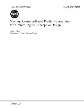
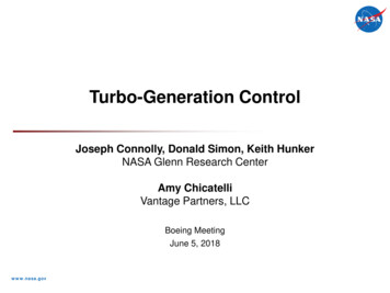
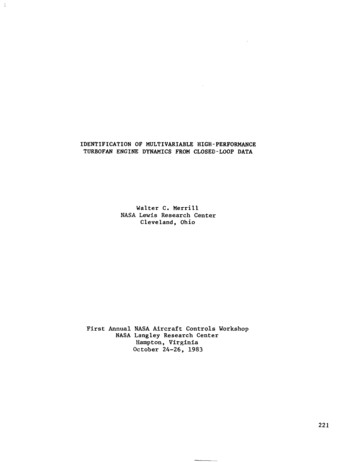
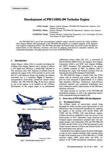
in Block-1 has been completed, with the running testson the first prototype engine being performed in 2012.The design is now being checked and evaluated throughrunning tests performed using these prototypes. In addition,Block-2 design has also been completed, incorporatingthe performance improvements, weight reductions, costreductions, and maintenance cost reductions obtainedby applying lessons learned through Block-1 designand testing. Currently, trial production and running testpreparations for the four Block-2 prototype engines arein progress. Figure 4 illustrates various running testconditions with the first prototype engine.FanLow pressurecompressorGear systemHigh pressure turbineHigh pressurecompressorLow pressure turbineEngine underdevelopment(PW1100G-JM)Conventionalengine3. PW1100G-JM featuresFigure 5 illustrates a comparison of the PW1100G-JMand conventional engine configurations. In contrast tothe conventional engine configuration on the bottom, thePW1100G-JM on the top drives the fan slowly at a smallernumber of revolutions per minute than the low pressurecompressor and the low pressure turbine thanks to theadvanced gear system, thereby achieving a high bypassratio, high propulsion efficiency, and low noise with alarger fan. By placing the advanced gear system betweenthe fan and the low pressure compressor, it is possible tomake the diameter smaller and reduce the number of stagesof the fast-spinning low pressure turbine compared to aconventional engine configuration.(a) Ground test(Image credit : P&W)Fig. 5 Comparison of PW1100G-JM and conventional engineconfigurations (1)Figure 6 illustrates the appearance of the PW1100G-JMengine. As Fig. 6 depicts, the fan section is larger thanthe core section that drives the fan. In order to reduce theweight of this large fan section, hollow aluminum fanblades derived from P&W technology are adopted, alongwith a fan case and fan exit guide vanes featuring IHI’scomposite materials technology. These composite materialparts are being manufactured by IHI Aerospace.(b) FTB test(Image credit : P&W)Fig. 4 PW1100G-JM first engine ground test and FTB test (1)V o l . 4 7 N o . 1 2 0 1425
Fan sectionCore section(a) Overall view of composite fan exit guide vanes and enlarged view ofinner/outer diameter sectionsOuter linerVane sectionHollow fan bladesComposite fan case(Image credit : P&W)Inner linerFig. 6 PW1100G-JM engine overview3.1 Fan sectionFigure 7 illustrates a composite fan case cross-section.When a composite fan case having a small thermalexpansion rate is used in combination with aluminum alloyfan blades having a large thermal expansion rate, the tipclearance of the fan increases under high-altitude, lowtemperature conditions, causing degraded fan efficiency.In order to prevent this phenomenon, a structure is adoptedin which a Thermal Conforming Liner (TCL) with analuminum alloy honeycomb is laid on the inner side of thecomposite bare case of the outer shell. Since this TCL issupported so as not to have its thermal expansion limitedby the composite bare case, the liner closely surroundingthe tips of the fan blades exhibits a magnitude of thermalexpansion that is equal to the fan blades under highaltitude (low-temperature) conditions, making it possible tominimize tip clearance during flight. Containment is alsodemanded of the fan case (keeping broken fan blades insidethe fan case). This fan case has already been confirmedby component testing as having the desired containmentcapacity.Next, Fig. 8 illustrates the composite fan exit guide vanestructure. The fan exit guide vanes have the function ofmaintaining high efficiency of the bypass flow compressedby the fan blades by rectifying it with low loss. In order tominimize interference with the pylons placed downstream,the fan exit guide vanes of the PW1100G-JM consist ofoptimally positioned vanes with five different camberComposite bare case (outer shell)(b) Enlarged view of inner vane support (inner liner omitted from view)Support(metal)Composite vaneFig. 8 Structure of composite fan exit guide vaneangles. From a structural perspective, the fan exit guidevanes are Structural Guide Vanes (SGVs) that support thefan case, and are able to withstand a large flight load aswell as fan blade off load. Moreover, in order to satisfythe rigidity demanded of the overall engine, a structureis adopted in which both ends (inner and outer diameter)of the composite vanes are held between sets of metalsupports.3.2 Low pressure compressorIn order to make the fan and the low pressure system rotorsrotate at different speeds, the low pressure compressorsection of the PW1100G-JM engine primarily consists of:① a Fan Drive Gear System (FDGS), ② main bearingsfor the fan and the low pressure system rotors, ③ a framesupporting the FDGS (front center body), ④ variable inletguide vanes, ⑤ a three-stage low pressure compressor, and⑥ a frame having mounts that supports the main bearing ofThermal conforming linerFig. 7 Composite fan case cross-section26V o l . 4 7 N o . 1 2 0 14
the high pressure system rotor (intermediate case). In atypical high-bypass ratio engine, the low pressure compressorsection and the high pressure compressor section havea frame that supports the main bearings for both the lowpressure system and high pressure system rotors as wellas the engine mount. Conversely, the PW1100G-JM enginefeatures a front center body for supporting the FDGSand the respective main bearings of the fan and thelow pressure system rotors, placed between the fan andthe low pressure compressor section. Furthermore, thisfront center body supports the fan case via the fan exitguide vanes.The low pressure compressor in which the rotors spinfaster than in a conventional engine consists of threestages having variable inlet guide vanes. The low pressurecompressor implements a three-dimensional vane designdeveloped using Computational Fluid Dynamics (CFD).In order to withstand high centrifugal forces, the rotarysection has a structure that resembles the rotary sectionof high pressure compressor, and all stages adopt anIntegrated Bladed Rotor (IBR) combining the blade sectionand the inner disk section. Figure 9 illustrates a lowpressure compressor stage-2 IBR.In addition, in order to ensure the required surge margin,the low pressure compressor exit includes a variable bleedvalve. Figure 10 illustrates the cross-section of a variablebleed valve. As Fig. 10 illustrates, the outer diameter exitof the bleed duct provided in the intermediate case can befully opened or closed by the valve moving in the axialdirection of the engine. Although the structure has basicallybeen proven in engines such as the V2500, Block-1running tests revealed that strong acoustic vibrations wereDisk sectionBlade sectionFig. 9 Low pressure compressor stage-2 IBRbeing produced in this duct, and so a number of candidateconfigurations were formulated with the cooperationof P&W, and CFD as well as rig testing confirmed thatshortening the duct length yields the required effect withthe least risk. From these results, the Block-1 parts wereimmediately reworked, and later running tests were carriedout safely. In addition, further improvements were made tothe Block-2 and type design.3.3 Low pressure turbine shaftBesides the fan and the low pressure compressor section,IHI is also responsible for the low pressure turbine shaft,which has established a solid record in prior enginedevelopment and mass production. The current shaftadopts materials that have been proven in prior models, butdiffers from these prior models in that it spins faster, whichdemands high speed balance during manufacturing fromthe perspective of rotor dynamics.Long duct(a) Block-1 configuration(b) Open state(c) Closed stateVariable 2.5 bleed valveIntermediate caseStage-3IBRLow pressure compressor caseFig. 10 Variable 2.5 bleed valve cross-sectionV o l . 4 7 N o . 1 2 0 1427
4. ConclusionThis paper introduces an overview of the PW1100G-JMdevelopment program, as well as the engineeringfeatures of the components being developed by IHI.Approximately one year remains until the scheduled enginetype certification in the third quarter of 2014, and so fardevelopment is proceeding smoothly.This development work is an international collaborativeproject by P&W, MTU, and JAEC. As this is the secondtime since the V2500 that our companies have participatedas equal partners in a joint venture, the program is beingdriven forward with renewed focus while tapping thepotential of our high-level design and manufacturingexpertise, such as IHI’s own composite materialstechnology. For the first time in the world, compositematerials are being adopted for use as SGVs in the fan exit28guide vanes, and we believe that such adoption of IHI’soriginal materials and designs after a variety of engineeringtests present a great opportunity to demonstrate IHI’simpact on and presence in the world.— Acknowledgements —The smooth pace of development up to this point wasmade possible by the generous support of the Ministryof Economy, Trade and Industry, in addition to the strongcooperation of related manufacturing, procurement, anddesign divisions within IHI as well as IHI Aerospaceand many domestic Japanese manufacturers. The authorsexpress their deepest thanks.REFERENCES (1) PurePower PW1000G Engine : http://www.purepowerengine.com/ (2013-9-18)V o l . 4 7 N o . 1 2 0 14
Airbus (France: Airbus SAS) is currently developing the A320neo (New Engine Option), and is aiming to achieve . acquire engine type certification in the third quarter of 2014, and enter into service in the fourth quarter of 2015. . advanced gear system, thereby achieving a high bypass ratio, high propulsion efficiency, and low noise with a .