Transcription
PDHonline Course M112 (3 PDH)Selection and Sizing of Pressure Relief ValvesInstructor: Randall W. Whitesides, PE2012PDH Online PDH Center5272 Meadow Estates DriveFairfax, VA 22030-6658Phone & Fax: 703-988-0088www.PDHonline.orgwww.PDHcenter.comAn Approved Continuing Education Provider
SELECTION AND SIZING OF PRESSURE RELIEF VALVESRandall W. Whitesides, P.E.GENERAL/SCOPE/INTRODUCTIONIntroductionThe function of a pressure relief valve is to protect pressure vessels, piping systems, and other equipmentfrom pressures exceeding their design pressure by more that a fixed predetermined amount. Thepermissible amount of overpressure is covered by various codes and is a function of the type ofequipment and the conditions causing the overpressure.Note: For ease of learning, the student isencouraged to print the glossary and refer tothe definitions of words or phrases as theyfirst appear while studying the coursematerial.It is not the purpose of a pressure relief valve to control or regulate the pressure in the vessel or systemthat the valve protects, and it does not take the place of a control or regulating valve.The aim of safety systems in processing plants is to prevent damage to equipment, avoid injury topersonnel and to eliminate any risks of compromising the welfare of the community at large and theenvironment. Proper sizing, selection, manufacture, assembly, test, installation, and maintenance of apressure relief valve are critical to obtaining maximum protection.Types, Design, and ConstructionA pressure relief valve must be capable of operating at all times, especially during a period of powerfailure; therefore, the sole source of power for the pressure relief valve is the process fluid.The pressure relief valve must open at a predetermined set pressure, flow a rated capacity at a specifiedoverpressure, and close when the system pressure has returned to a safe level. Pressure relief valves mustbe designed with materials compatible with many process fluids from simple air and water to the mostcorrosive media. They must also be designed to operate in a consistently smooth manner on a variety offluids and fluid phases. These design parameters lead to the wide array of pressure relief valve productsavailable in the market today.
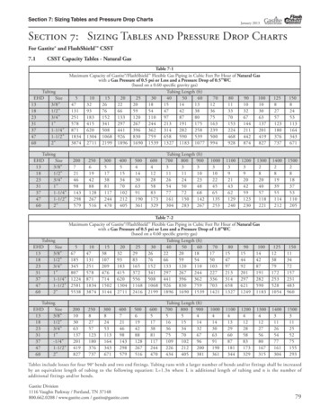
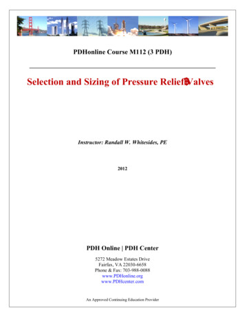
FIGURE 1 - TWO TYPES OR RELIEF VALVESThe standard design safety relief valve is spring loaded with an adjusting ring for obtaining the properblowdown and is available with many optional accessories and design features. Refer to Figure 1 forcross-sectional views of typical valves. The bellows and balanced bellows design isolate the process fluidfrom the bonnet, the spring, the stem, and the stem bushing with a bellows element. Jacketed valvebodies are available for applications requiring steam or heat transfer mediums to maintain viscosity orprevent freezing. Pilot-operated valves are available with the set pressure and blowdown control locatedin a separate control pilot. This type of valve uses the line pressure through the control pilot to the pistonin the main relief valve and thereby maintains a high degree of tightness, especially as the set pressure isbeing approached. Another feature of the pilot-operated valve is that it will permit a blowdown as low as2 %. The disadvantage of this type of valve is its vulnerability to contamination from foreign matter in thefluid stream.CODES AND STANDARDSIntroductionSince pressure relief valves are safety devices, there are many Codes and Standards in place to controltheir design and application. The purpose of this section of the course is to familiarize the student withand provide a brief introduction to some of the Codes and Standards which govern the design and use ofpressure relief valves. While this course scope is limited to ASME Section VIII, Division 1, the otherSections of the Code that have specific pressure relief valve requirements are listed below. The portionsof the Code that are within the scope of this course are indicated in red:
List of Code Sections Pertaining to Pressure Relief ValvesSection ISection III, Division 1Section IVSection VISection VIISection VIII, Division 1Appendix 11Appendix MSection VIII, Division 2B31.3, Chapter II, Part 3B31.3, Chapter II, Part 6Power BoilersNuclear Power Plant ComponentsHeating BoilersRecommended Rules for the Care and Operation of Heating BoilersRecommended Rules for the Care of Power BoilersPressure VesselsCapacity Conversions for Safety ValvesInstallation and OperationPressure Vessels - Alternative RulesPower Piping - Safety and Relief ValvesPower Piping - Pressure Relief PipingASME specifically states in Section VIII, Division 1, paragraph UG-125 (a) “All pressure vessels withinthe scope of this division, irrespective of size or pressure, shall be provided with pressure relief devices inaccordance with the requirements of UG-125 through UG-137.”Reference is made to the ASME Boiler and Pressure Vessel Code, Section VIII, Division 1. Theinformation in this course is NOT to be used for the application of overpressure protection to powerboilers and nuclear power plant components that are addressed in the Code in Section I and Section IIIrespectively. The student should understand that the standards listed here are not all inclusive and thatthere exists specific standards for the storage of chlorine, ammonia, compressed gas cylinders, and theoperation of refrigeration units, among probable others.A Brief History of the ASME CodeMany states began to enact rules and regulations regarding the construction of steam boilers and pressurevessels following several catastrophic accidents that occurred at the turn of the twentieth century thatresulted in large loss of life. By 1911 it was apparent to manufacturers and users of boilers and pressurevessels that the lack of uniformity in these regulations between states made it difficult to construct vesselsfor interstate commerce. A group of these interested parties appealed to the Council of the AmericanSociety of Mechanical Engineers to assist in the formulation of standard specifications for steam boilersand pressure vessels. (The American Society of Mechanical Engineers was organized in 1880 as aneducational and technical society of Mechanical Engineers). After years of development and publiccomment the first edition of the code, ASME Rules of Construction of Stationary Boilers and forAllowable Working Pressures, was published in 1914 and formally adopted in the spring of 1915. Fromthis simple beginning the code has now evolved into the present eleven section document, with multiplesubdivisions, parts, subsections, and mandatory and non-mandatory appendices.The ASME Code Symbol Stamp and the letters “UV” on a pressure relief valve indicate that the valve hasbeen manufactured in accordance with a controlled quality assurance program, and that the relievingcapacity has been certified by a designated agency, such as the National Board of Boiler and PressureVessel Inspectors.
Adoption of the ASME Code by the StatesAs of this writing, all states of the United States, with the exception of South Carolina, have adopted theASME Code as jurisdictional law. The student should consult with local regulatory authorities, e.g. stateagencies, to determine any specialized jurisdictional requirements for pressure relief valves that may beapplicable.EQUATION NOMENCLATUREUnless otherwise noted, all symbols used in this course are defined as follows:A Valve effective orifice area, in².C Flow constant determined by the ratio of specific heats, see Table 2 (use C 315 if k is unknown)G Specific gravity referred to water 1.0 at 70 FK Coefficient of discharge obtainable from valve manufacture (K 0.975 for many nozzle-type valves)Kb Correction factor due to back pressure. This is valve specific; refer to manufacturer’s literature.Kn Correction factor for saturated steam at set pressures 1,500 psia, see Equation 6Kp Correction factor for relieving capacity vs. lift for relief valves in liquid service, see Equations 1 & 2Ksh Correction factor due to the degree of superheat in steam (Ksh 1.0 for saturated steam)Kv Correction factor for viscosity, see Equations 8 & 9 (use Kv 1.0 for all but highly viscous liquids)Kw Correction factor due to back pressure for use with balanced bellows valvesM Molecular weight, see Table 2 for values of some common gasesP1 Upstream pressure, psia (set pressure overpressure atmospheric pressure)!P Differential pressure (set pressure, psig ! back pressure, psig)Q Flow, gpmT Inlet vapor temperature, RRne Reynolds numbers,W Flow, lb/hrZ Compressibility factor (use Z 1 for ideal gas)" Liquid dynamic (absolute) viscosity, centipoise
SIZING AND SELECTIONIntroductionPressure relief valves must be selected by those who have complete knowledge of the pressure relievingrequirements of the system to be protected and the environmental conditions particular to that installation.Too often pressure relief valve sizes are determined by merely matching the size of an existing availablevessel nozzle, or the size of an existing pipe line connection.Correct and comprehensive pressure relief valve sizing is a complex multi-step process that should followthe following stepwise approach:1. Each piece of equipment in a process should be evaluated for potential overpressure scenarios.2. An appropriate design basis must be established for each vessel. Choosing a design basis requiresassessing alternative scenarios to find the credible worst case scenario.3. The design basis is then used to calculate the required pressure relief valve size. If possible, the sizingcalculations should use the most current methodologies incorporating such considerations as twophase flow and reaction heat sources.This course addresses pressure relief valves as individual components. Therefore, detailed design aspectspertaining to ancillary piping systems are not covered. These are clearly noted in the course. Thesedesign issues can be addressed by piping analysis using standard accepted engineering principles; theseare not within the scope of this course. Where relief device inlet and outlet piping are subject to importantguidance by the ASME Code, it is so noted.In order to properly select and size a pressure relief valve, the following information should be ascertainedfor each vessel or group of vessels which may be isolated by control or other valves. The data required toperform pressure relief valve sizing calculations is quite extensive. First, the equipment dimensions andphysical properties must be assembled. Modeling heat flow across the equipment surface requiresknowledge of the vessel material’s heat capacity, thermal conductivity, and density (if vessel mass isdetermined indirectly from vessel dimensions and wall thickness). The vessel geometry – vertical orhorizontal cylinder, spherical, etc. – is a necessary parameter for calculating the wetted surface area, wherethe vessel contents contact vessel walls. Second, the properties of the vessel contents must be quantified.This includes density, heat capacity, viscosity, and thermal conductivity. Values of each parameter arerequired for both liquid and vapor phases. Boiling points, vapor pressure, and thermal expansioncoefficient values also are required. Ideally, the properties will be expressed as functions of temperature,pressure, and compositions of the fluid.Determination of the Worst-Case Controlling ScenarioAs process plants become larger and are operated closer to safety limits, a systematic approach to safetybecomes a necessity.The most difficult aspect of the design and sizing of pressure relief valves is ascertaining the controllingcause of overpressure. This is sometimes referred to as the worst case scenario. Overpressure inequipment may result from a number of causes or combination of causes. Each cause must beinvestigated for its magnitude and for the probability if its occurrence with other events. The objectivemight be to document why the particular design basis is the correct choice. The question that will always
remain: which scenario is the credible worst case? Among the techniques available to solve this problemis fault-tree analysis. A fault tree is a graphical representation of the logical connections between basicevents (such as a pipe rupture or the failure of a pump or valve) and resulting events (such as anexplosion, the liberation of toxic chemicals, or over-pressurization in a process tank). A completetreatment of fault-tree theory and analysis is beyond the scope of this course.The usual causes of overpressure and ways of translating their effects into pressure relief valverequirements are given in the following list. In most cases, the controlling overpressure will be thatresulting from external fire.1.2.3.4.5.6.7.8.9.10.Heat from external fireEquipment failureFailure of Condenser systemFailure of Cooling MediumFailure of Control systemChemical reactionsEntrance of Volatile FluidClosed OutletsThermal Expansion of LiquidsOperating errorPressure relief valves must have sufficient capacity when fully opened to limit the maximum pressurewithin the vessel to 110% of the maximum allowable working pressure (MAWP). This incrementalpressure increase is called the pressure accumulation. However, if the overpressure is caused by fire ofother external heat, the accumulation must not exceed 21% of the MAWP.Section VIII does not outline a detailed method to determine required relieving capacity in the case ofexternal fire. Appendix M-14 of the Code recommends that the methods outlined in Reference 3 beemployed. The student is directed to Reference 7 for an excellent treatment, including examples, of themethodology of API Recommended Practice 520 (Reference 3).Determination of Set Point PressureProcess equipment should be designed for pressures sufficiently higher than the actual working pressure toallow for pressure fluctuations and normal operating pressure pea
The pressure relief valve must open at a predetermined set pressure, flow a rated capacity at a specified overpressure, and close when the system pressure has returned to a safe level. Pressure relief valves must be designed with materials compatible with many process fluids from simple air and water to the most corrosive media. They must also be designed to operate in a consistently smooth manner on a