Transcription
AMMONIA PRESSURE-RELIEF VALVESAMMONIA PRESSURE-RELIEF VALVES
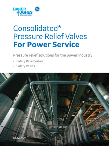
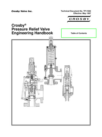
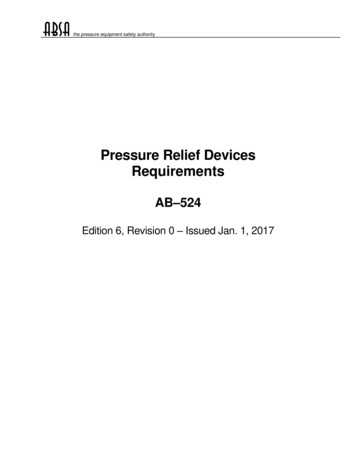
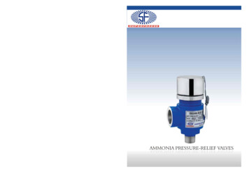
AMMONIA PRESSURE-RELIEF VALVESTYPE: SRVINTRODUCTIONSUPERFREEZE pressure relief valves are designed toprovide emergency relief from excessive pressure inrefrigerant containing vessels. These tamper-resistantvalves are accurately set and sealed by qualifiedtechnicians at the factory.Our safety valve design features the most reliablemethod of safely relieving pressure. The virgin Teflonseal mated with the stainless steel multiple crown ring,provide an outstanding sealing action. The combinationassures a non-stick and accurate pop-off pressurerelease. The design incorporates a special extra lift,pop-open feature for high relieving capacity.STAINLESS STEELSPRINGSPRING GUIDESTAINLESS STEELPISTONSTAINLESS STEELSEAT INSCRTBODYSEAT DSICAPPLICATIONSPressure relief valves helps meet the requirements of ANSI/ASHRAE 15-1994 safety code for Mechanical Refrigeration aswell as other world wide codes. This code requires pressure vessels of all refrigeration systems to be protected by a pressure reliefdevice or other approved means to safely relieve pressure in the event of fire or other abnormal conditions. Once installed, isready to vent to atmosphere any temporary excessive overpressure inside of a vessel. After discharge, these valves will attempt toreseat to minimize loss of refrigerant. However, once any relief valve has discharged, it must be replaced as soon as possiblebecause debris may have settled on the seat during discharge.
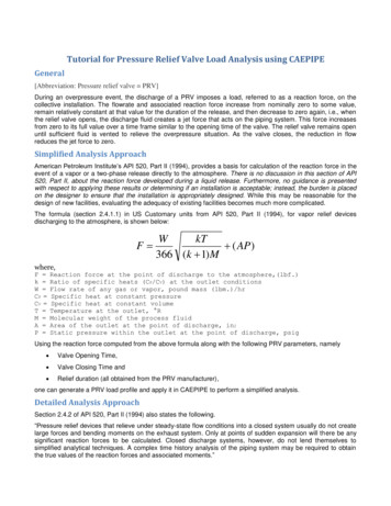
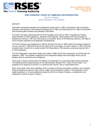
AMMONIA PRESSURE-RELIEF VALVESMATERIAL SPECIFICATIONSBodyPistonSpringSeat insertSeat DiscsCapCap O-RingMaximum Temperature RatingSafe Working PressureSetting Range::::::::::Nodular ironStainless steel AISI-304Stainless SteelStainless steelPremium grade virgin Teflon (PTFE)Steel, Nickel chrome PlatedNeoprene115 C (240F)365 psig (25 bar)150 to 350 psig (10.4 to 24 bar)INSTALLATIONSafety relief valves should not be discharged prior to installation, other than at time of factory setting. If the system is to bepressure tested to pressures at or higher than the relief valve setting, the relief valve should be removed while the system isbeing tested. Discharging the valve during system pre-test could cause foreign material and contamination to lodge on thevalve seat disc. This would cause permanent leak or lower the initial leak pressure. In either event, the valve would have tobe replaced.Do not attempt to change the pressure setting of safety relief valves in the field. Relief valve springs have a limited range ofpressure settings and a field adjustment may exceed this range reducing stem lift and discharge capacity. The valve should bereturned to manufacturer for re-setting and re-sealing.INSTALLATION DIMENSIONSOUTLETSAFETY VLAVECat No.SRV 1520SRV 1525SRV 2025SRV 2532SIZE15mm X 20mm15mm X 20mm20mm X 25mm25mm ”FPT1” FPTOUTLET¾”FPT1” FPT1” FPT1-1/4”FPTINLET
AMMONIA PRESSURE-RELIEF VALVESCONNECTIONSRelief valves are connected as nearly as practicable directly to the pressure vessel above the liquid refrigerant level. The opening towhich the relief valve is connected shall have at least the area of the relief valve Inlet. There should not be a stop valve between thevessel and the relief valve or between the relief valve and the point of discharge.For relief valves used on pressure vessels having 10 cubic feet of internal gross volume or more, a relief device system consisting ofa three-way valve and two relief valves in parallel is required. This arrangement for any size system containing a substantial chargeof refrigerant provides a convenient method for relief valve maintenanceLOCATIONValves relieving to atmosphere may be installed on systems operating as low as -100 C provided location is in ambienttemperatures that are normally above 0 C.REQUIRED VALVE CAPACITY FOR PRESSURE VESSELSThe ANSI/ASHRE 15-1994 safety code gives the following formula for determining the necessary relief valve capacityfor a given pressure vessel. The minimum required discharge capacity of the safety relief valve shall be:C 13.1(f)(D)(L)WhereC Minimum required discharge capacity of the relief valve in SCFM of air13.1 Constant to convert air, lb/min to scfmf Factor dependent upon kind of refrigerantAmmonia (Refrigerant 717)f 0.5Refrigerant F-12, F-22f 1.6D Outside diameter of vessel in ft.L Length of vessel in ft.
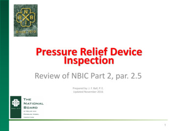
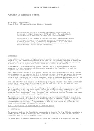
AMMONIA PRESSURE-RELIEF VALVESPRESSURE-RELIEF VALVE CAPACITY itylb/min17541.8Standard Pressure Settings (psig)200 225 250 275 300465257.2 62.2 inscfm53.070261.881569.692077.3 8592.5 100 109 1171027 1136 1245 1351 1460 1567765841915Important note: these are atmospheric relief valves. Setting equal pressure above atmosphere when outlet is connected via properschedule 40 piping to the atmosphere (out side). (scfm Standard Cubic Feet per Minute}PART LISTITEM123456789DESCRIPTIONBODYINSERTPISTONSEAT RINGSPINDLESPRINGTIGHTENING NUTCOVER PLATE“O” RINGQTY111111111PART )ORDERING INFORMATION PRESSURE-RELIEF VALVESCat. No.SRV1520SRV1525SRV2025SRV2532Threaded ConnectionBottom Inlet1/2" FPT1/2" FPT3/4” FPT1" FPTSide Outlet3/4" FPT1" FPT1” FPT1-1/4" FPTTo Order: Please specify catalog number, inlet / outlet connection size, and pressure settingStandard pressure setting: 150*, 175, 200, 225, 250*, 275, 300*, 325, 350 psig. (*stock pressure setting.)
AMMONIA PRESSURE-RELIEF VALVESGENERAL PRECAUTIONSNever expose face or body to a connected relief valve exit or piping connected thereto.Make sure valve setting and capacity (see Nameplate information Section) meet requirements per system design inaccordance with local and national regulations.Install pressure-relief valve connected directly to the pressure vessel with no shut-off valves and at a location above the liquidrefrigerant level.Never attempt to reset or change valve setting.Do not discharge valves prior to installation or when pressure testing.Do not install shut-off valves in line with pressure relief valves.Install valves in locations where they will not be damaged by moving equipment such as lift trucks, etc.Install valves in a manner that enables them to be replaced.Avoid trapped ice build-up between valves and other equipment.Do not install valves in a refrigerated space unless precautions are taken to prevent moisture migration into the valve body orthe relief vent line.Be sure to isolate the valve and related piping from the refrigeration system and pump out pressure to zero before attemptingto install or replace any pressure-relief valve and be sure to avoid residual refrigerant when doing so.Apply a modest amount of thread sealing compound to external pipe threads only in order to avoid getting compound insidevalve.Vent relief valve exit to a safe outdoor location in an approved manner away from people and building openings.Pressure test all valves and related piping for leaks. When testing a dual pressure relief system, the three-way valve stem shouldbe in the mid-position, ensuring that all valves are properly leak tested.When a dual pressure relief system is being put into service, the three-way valve stem should be positioned so that only onevalve is activated. While the valve can be either front-seated (front port is closed) or back-seated (back port is closed), theback-seated position is recommended because it takes pressure off the packing and reduces the possibility of packing leaks.Use brackets or hangers to support pipe and prevent valve from being overly stressed.Do not put undue stress on valve by using it to stretch or align pipe.ALWAYS REPLACE PRESSURE-RELIEF VALVES ONCE THEY HAVE DISCHARGED.
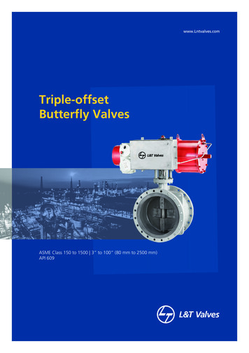
AMMONIA PRESSURE-RELIEF VALVESPIPING RELIEF VALVES BACK INTO THE SYSTEMRefrigeration systems containing large ammonia charges ( 10,000 pounds) can benefit by piping relief valves back into thesystem. Safety pressure relief valves are subject to “inspection and testing” periodically under the EPA Risk ManagementPrograms. Relief valves that are piped back into the system can be expected to perform over much longer periods betweeninspections than relief valves exposed to contaminants and corrosion from exposure to the atmosphere. Another benefit ofdischarging back into the system is the avoidance of liquid spills from oil pots, liquid coolers and other liquid filled components.When piping relief valves back into the system, the total of the set points of relief valves in series should not exceed the allowedworking pressure of upstream components. Here are a few examples of suitable application of piping relief valves back into thesystem.400 psi Oil Coolers on screw compressor :Use 75 psi or 100 psi set point liquid relief valves discharging into 300 psi oil separator.250 psi Surge drums on evaporators :Use 75 psi or 100 psi set point valves discharging to suction line downstream of the suction stop valve, using 150 psiset point relief valves on the main house accumulator.250 psi Evaporative condensers :A relief valve is not required on evaporative condenser coil however, when desired, use 75 psi or 100 psi set pointvalve discharging to the condenser drain downstream of the condenser outlet stop valve.250psi Oil Drain drum :Use 75 psi or 100 psi set point valve discgarging to 150 psi suction accumulator.250 psi Shell and tube or baudelot plate evaporator :Use 75 psi or 100 psi set point valve discharging to 150 psi suction downstream of evaporator outlet stop valve.300 psi Screw compressor :Use 250 psi set point valve discharging to suction line upstream of suction stop valve. This valve is primarily to protectmotor from overload in case screw is started with a closed discharge valve.The effect of the potential from discharges of upstream relief valves should be considered in sizing downstream atmospheric safetyrelief valves.
AMMONIA PRESSURE-RELIEF VALVESWHEN AMMONIA RELIEF VALVES DISCHARGE INTO WATERCorrosion: There is a concern about corrosion in relief valves when the discharge is piped into a tank of water. This corrosion isdue to exposure to water vapor and air in the piping. SUPERFREEZE safety relief valves use ductile iron bodies, and stainlesssteel and Teflon from internal parts. Since these materials resist corrosion, the accepted industries practice of inspecting orreplacing safety relief valves every five years should provide adequate protection from corrosion in the valves.Back Pressure: Another concern is the reduction of relief valve capacity caused by the head of water over the discharge pipeoutlet when it is submerged. The various codes do not provide methods to address this subject except to require due allowancefor pressure drop in the downstream section.Vacuum Service1When safety relief valves are connected to systems that operate below atmospheric pressure, a reasonable precaution isto install a check valve in the discharge line before it enters the water tank. This will prevent a vacuum from sucking water into thesystem should a relief valve leak or not reseat after a release. The check valve may also prevent the migration of water vapor so asto reduce the potential for corrosion in the relief valve.2An alternative is to use a check valve mounted in a "tee" in the run of the discharge piping. This will not affect thepressure drop in the discharge, but will act as a "vacuum breaker". Either of the two methods suggested above will protect againstdiluting the ammonia with water should the relief valve leak after operating.Where Water Tanks are Required: The requirement for discharge into a tank of water appears in the Uniform Mechanical Code,published by ICBO, Section 1119 for ammonia systems. The international Mechanical Code, does require that refrigeratingsystems comply with the ASHRAE-15 Safety Code, and that ammonia refrigerating systems in a industrial occupancy conform toIIAR-2 Equipment, Design and Installation of Ammonia Mechanical Refrigerating Systems. ASHRAE-15 offer three methodsfor ammonia discharge: i.e. , into the atmosphere, into a tank of water, or into other approved treatment systems. Appendix Bprovides guidelines for emergency discharge of refrigerants when required by local codes. In IIAR-2, the preferred discharge ofdischarge into a tank of water. When local mechanical codes require the use of a water tank for absorbing the discharge fromammonia relief valves, refer to ASHRAE 15-1994 paragraph 9.7.8.2(b) for details. Note : IIAR-2 in the process ofrevision to conform to the specifications now in ASHRAE -15.ICBO - International Conference Building Officials Located in California.SUPERFREEZE INDIA LIMITED122,Qutab Plaza DLF Phase-1Gurgaon-122002 (Haryana), India.Tel: 91-124-4301636, 919810048749Fax: 91-1276-241549Email: sales@superfreeze.comWebsite: www.superfreeze.com
Relief valves are connected as nearly as practicable directly to the pressure vessel above the liquid refrigerant level. The opening to which the relief valve is connected shall have at least the area of the relief valve Inlet. There should not be a stop valve between the vessel and the relief valve or between the relief valve and the point of discharge. For relief valves used on pressure .