Transcription
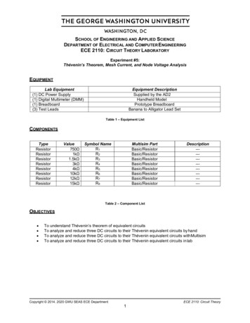
SCHOOL OF ENGINEERING AND APPLIED SCIENCEDEPARTMENT OF ELECTRICAL AND COMPUTER ENGINEERINGECE 2110: CIRCUIT THEORY LABORATORYExperiment #5:Thévenin’s Theorem, Mesh Current, and Node Voltage AnalysisEQUIPMENTLab Equipment(1) DC Power Supply(1) Digital Multimeter (DMM)(1) Breadboard(3) Test LeadsEquipment DescriptionSupplied by the AD2Handheld ModelPrototype BreadboardBanana to Alligator Lead SetTable 1 – Equipment 5kΩ3kΩ4kΩ10kΩ12kΩ15kΩSymbol NameR1R2R3R4R5R6R7R8Multisim orBasic/ResistorDescription-----------------Table 2 – Component ListOBJECTIVES To understand Thévenin’s theorem of equivalent circuitsTo analyze and reduce three DC circuits to their Thévenin equivalent circuits by handTo analyze and reduce three DC circuits to their Thévenin equivalent circuits with MultisimTo analyze and reduce three DC circuits to their Thévenin equivalent circuits in labCopyright 2014. 2020 GWU SEAS ECE Department1ECE 2110: Circuit Theory
SEASExperiment #5: Thévenin’s Theorem, Mesh Current, and Node Voltage AnalysisINTRODUCTIONIn this lab, you must find the Thévenin and Norton equivalents for three separate circuits. You will firstperform the analysis by hand using the techniques that you have learned in lecture and in your homework.Then, you will simulate the circuits in Multisim, using it to find the Thévenin and Norton equivalents. Finally,you will build the three circuits in lab and measure them to find the Thévenin and Norton equivalents. Inyour lab report, you will compare and analyze the results from each technique.Thévenin’s TheoremThévenin’s Theorem for DC circuits states that any two port linear network may be replaced by a singlevoltage source with an appropriate internal resistance. The Thévenin equivalent will produce the same loadcurrent and voltage as the original circuit to any load. Consequently, if many different loads or sub- circuitsare under consideration, using a Thévenin equivalent usually proves to be a much quicker method ofanalysis. Any complex circuit consisting of multiple sources and components can be reduced to a singlevoltage source, the Thévenin voltage, in series with its internal resistance, the Thévenin resistance.The Thévenin voltage, VTH, is found by determining the open-circuit output voltage. The Théveninresistance, RTH, is found by replacing any DC sources with their internal resistances and determining theresulting combined resistance as seen from the two ports using standard series-parallel analysistechniques. A voltage source would be replaced by a short, zero resistance, and a current source would bereplaced by an open, infinite resistance. In the laboratory, the Thévenin resistance may be found using anohmmeter (again, replacing the sources with their internal resistances) or by using the matched loadtechnique. The matched load technique involves replacing the load with a variable resistance and thenadjusting it until the load voltage is precisely one-half of the unloaded voltage. This would imply that theother half of the voltage must be dropped across the equivalent Thevenin resistance, and as the Thevenincircuit is a simple series loop then the two resistances must be equal as they have identical currents andvoltages.Norton’s TheoremNorton’s Theorem for DC circuits states that any two port linear network may be replaced by a singlecurrent source with an appropriate internal resistance in parallel. It is closely related to Thévenin’s Theorem,and either simplified representation works equally well. Any complex circuit consisting of multiple sourcesand components can be reduced to a single current source, the Norton or short-circuit current, in parallelwith its internal resistance, which is the same as the Thévenin resistance.The Norton current is found by determining the short-circuit output current, ISC. The internal resistance canbe determined in the same manner as was explained above for the Thévenin resistance.Figure 1 – Thévenin Equivalent CircuitCopyright 2014. 2020 GWU SEAS ECE DepartmentFigure 2 – Norton Equivalent Circuit2ECE 2110: Circuit Theory
SEASExperiment #5: Thévenin’s Theorem, Mesh Current, and Node Voltage AnalysisMesh Current AnalysisMulti-source DC circuits may be analyzed using a mesh current technique. The process involves identifyinga minimum number of small loops such that every component exists in at least one loop. Kirchhoff’sVoltage Law is then applied to each loop, meaning that the algebraic sum of the voltages around eachloop must equal zero. The loop currents are referred to as mesh currents as each current interlocks ormeshes with the surrounding loop currents. As a result, there will be a set of simultaneous equationscreated, an unknown mesh current for each loop. Once the mesh currents are determined, various branchcurrents and component voltages may be derived.Node Voltage AnalysisMulti-source DC circuits may be analyzed using a node voltage technique. The process involves identifyingall of the circuit nodes, a node being a point where various branch currents combine. A reference node,usually ground, is included. Kirchhoff’s Current Law is then applied to each node, meaning that thealgebraic sum of the currents into and out of each node must equal zero. Consequently, a set ofsimultaneous equations are created with an unknown voltage for each node with the exception of thereference. In other words, a circuit with a total of five nodes including the reference will yield four unknownnode voltages and four equations. Once the node voltages are determined, various branch currents andcomponent voltages may be derived.How to Use All Three DC Voltage OutputsFor Part II of this lab, you will need to build a circuit that has three separate voltage sources. It is veryimportant that you know how to properly utilize the AD2 so that you can create this complex circuit.Remember that the AD2 can supply anywhere between -5V to 5V. The AD2 can produce DC voltagethrough the "Supplies" tab and the "Wavegen" tab. Within the Wavegen tab, you just need to set the"type" to DC, and then change the offset to whatever voltage you need. The play button for theWavegen tab does not control it in this case. Above the “Type” selection box is a white check boxthat says “enable”. This box is what turns the DC Wavegen on and off. The different voltage sourceswithin the AD2 and its adapter all share a common ground. If the negative sides of the voltage sourcesare grounded in your schematic, they need to be tied together to the same ground. To do this, make sureto connect the bottoms (the ground wire) of the voltage sources onto the same ground rail. Without theadapter, the ground wires are the black wires coming from the pins with the down arrows, which are thirdfrom the left. An example of this is shown below.Figure 3 - AD2 Power Supply ConnectionsCopyright 2014. 2020 GWU SEAS ECE Department3ECE 2110: Circuit Theory
SEASExperiment #5: Thévenin’s Theorem, Mesh Current, and Node Voltage AnalysisPRELABThis prelab consists of three circuits to be reduced using Thévenin's Theorem. You are required to completeboth hand calculations and Multisim simulations before coming to lab. This prelab requires more analysisthan previous labs; please allocate the proper amount of time to complete it early on.Part I – Circuit #1 AnalysisFigure P.1.1 – Circuit #1In Figure P.1.1, the voltage source Vs 5V and the current source Is 2 mA.1.2.Calculate the following from the perspective of terminals A and B. Show all work.a. Thévenin voltage (VTH)b. Thévenin resistance (RTH)c. Norton current, also called the short-circuit current (ISC)Use your results to fill in the appropriate values for Figure P.1.2 and Figure P.1.3 below:Figure P.1.2 – Thévenin Equivalent of Circuit #1Copyright 2014. 2020 GWU SEAS ECE DepartmentFigure P.1.3 – Norton Equivalent of Circuit #14ECE 2110: Circuit Theory
SEASExperiment #5: Thévenin’s Theorem, Mesh Current, and Node Voltage AnalysisFigure P.1.4 – Circuit #1 with Load Resistor Attached3.Calculate the voltage across and current through RL for the circuit in Figure P.1.4, which hasa 1kΩ load resistor RL attached across terminals A and B.Figure P.1.5 – Thévenin Equivalent with Load Resistor4.5.Figure P.1.6 – Norton Equivalent with Load ResistorCalculate the voltage across and current through RL for these circuits, which have a 1kΩ loadresistor RL attached across terminals A and B.Simulate the circuit from Figure P.1.1 in Multisim:a. Use the tutorial on the lab website (Multisim Tutorial #2: Using Multisim to find VTH,ISC, RTH) to learn how to find VTH, ISC, and RTH for a circuit in Multisim.b. Build the circuit in Figure P.1.1 in Multisim and find its VTH, ISC, and RTH.c. Build the equivalent circuits in Figure P.1.2 and Figure P.1.3 in Multisim.d. In Multisim, attach a 1kΩ load resistor (RL) to the circuit as you did in Figure P.1.4.Measure and record the simulated voltage across and current through RL.e. In Multisim, attach 1kΩ load resistors (RL) to the equivalent circuits in Figure P.1.5 andFigure P.1.6. Measure and record the simulated voltage across and current through RL.Electrical QuantityVTHRTHISCOriginal CircuitVRLIRLEquivalent CircuitVRLIRLCalculatedSimulatedPercent ErrorTable P.1 – Circuit #1 DataCopyright 2014. 2020 GWU SEAS ECE Department5ECE 2110: Circuit Theory
SEASExperiment #5: Thévenin’s Theorem, Mesh Current, and Node Voltage AnalysisPart I – Circuit #1 Analysis Continued6.Now Simulate the circuit shown in Figure P.1.7, which replaces the current source with a voltagesource (V2). The value of V2 is set at 1.44V.a. Measure the voltage and current across point A* and B*. What do you notice about thesevalues compared to those in Table P.1?b. Now Insert RL into this circuit, shown in Figure P.1.8. Measure the current going throughand the voltage across RL. What do you notice about these values compared to those inTable P.1?Figure P.1.7Figure P.1.8Copyright 2014. 2020 GWU SEAS ECE Department6ECE 2110: Circuit Theory
SEASExperiment #5: Thévenin’s Theorem, Mesh Current, and Node Voltage AnalysisPart II – Circuit #2 AnalysisFigure P.2.1 – Circuit #2In Figure P.2.1, the voltage sources V1 3V, V2 5V, and V3 -5V.1.2.3.Calculate the following from the perspective of terminals A and B. Show all work.a. Thévenin voltage (VTH)b. Thévenin resistance (RTH)c. Norton current, also called the short-circuit current (ISC)Use your results to fill in the appropriate values and draw the Thévenin and Norton equivalentsas you did in Part I.Attach a 1kΩ load resistor RL across terminals A and B in Figure P.2.1 and calculate thevoltage across and current through RL for the new circuit.4.Attach a 1kΩ load resistor RL across terminals A and B in the equivalent circuits that you drewand calculate the voltage across and current through RL for the new circuits.6.Simulate the circuit from Figure P.2.1 in Multisim:a. Build the circuit in Figure P.2.1 in Multisim and find its VTH, ISC, and RTH.b. Build the equivalent circuits in Multisim.c. In Multisim, attach a 1kΩ load resistor (RL) to the original circuit. Measure and recordthe simulated voltage across and current through RL.d. In Multisim, attach 1kΩ load resistors (RL) to the equivalent circuits. Measure andrecord the simulated voltage across and current through RL.Electrical QuantityVTHRTHISCOriginal CircuitVRLIRLEquivalent CircuitVRLIRLCalculatedSimulatedPercent ErrorTable P.2 – Circuit #2 DataCopyright 2014. 2020 GWU SEAS ECE Department7ECE 2110: Circuit Theory
SEASExperiment #5: Thévenin’s Theorem, Mesh Current, and Node Voltage AnalysisPart III – Circuit #3 AnalysisFigure P.3.1 – Circuit #3In Figure P.3.1, the voltage sources V1 3V, V2 6V, and V3 9V.1.2.3.Calculate the following from the perspective of terminals A and B. Show all work.a. Thévenin voltage (VTH)b. Thévenin resistance (RTH)c. Norton current, also called the short-circuit current (ISC)Use your results to fill in the appropriate values and draw the Thévenin and Norton equivalentsas you did in Part I and Part II.Attach a 1kΩ load resistor RL across terminals A and B in Figure P.3.1 and calculate thevoltage across and current through RL for the new circuit.4.Attach a 1kΩ load resistor RL across terminals A and B in the equivalent circuits that you drewand calculate the voltage across and current through RL for the new circuits.7.Simulate the circuit from Figure P.3.1 in Multisim:a. Build the circuit in Figure P.3.1 in Multisim and find its VTH, ISC, and RTH.b. Build the equivalent circuits in Multisim.c. In Multisim, attach a 1kΩ load resistor (RL) to the original circuit. Measure and recordthe simulated voltage across and current through RL.d. In Multisim, attach 1kΩ load resistors (RL) to the equivalent circuits. Measure andrecord the simulated voltage across and current through RL.Electrical QuantityVTHRTHISCOriginal CircuitVRLIRLEquivalent CircuitVRLIRLCalculatedSimulatedPercent ErrorTable P.3 – Circuit #3 DataCopyright 2014. 2020 GWU SEAS ECE Department8ECE 2110: Circuit Theory
SEASExperiment #5: Thévenin’s Theorem, Mesh Current, and Node Voltage AnalysisLABPart I – Circuit #1 MeasurementsFigure 1.1 – Circuit #11. Build the circuit from Part I of the prelab shown again in Figure 1.1 on a breadboard. Make sure you have WaveFormsopen and your AD2 is connected to it. For this circuit, it is recommended that you use the DC portion of the “Wavegen” as V2.2. Measure the circuit to find VTH, RTH, and ISC.a. VTH Measurement: Use the DMM to measure the voltage between terminals A* and B*.b. ISC Measurement: Switch the DMM to current mode and measure the current betweenterminals A* and B*.Note: Remember that the DMM in current mode has a very small internal resistance, such that connecting itdirectly between terminals A* and B* short-circuits A* to B*. This easily gives us the short-circuit current inthis case.c. RTH Measurement:i. Turn off and remove the DC power supply connections used for Vs and Vs2.ii. Use wires to connect where both voltage sources Vs and Vs2 originally were in your circuit.iii.Note: As discussed in the Introduction, we must “short” the voltage sources. In real life, however, wecannot simply short the power supply as it would overload it. ***You absolutely must remove thepower supply before shorting it.***Measure the resistance between terminals A* and B* using the DMM.3. Remove the wires used to short the voltage sources and reconnect the AD2 to the circuit.4. Connect a 1kΩ load re s i s t o r RL to t e r m i n a l s A* a n d B* a n d measure the voltage a c r o s sand the current through RL.5. Build the Thévenin Equivalent circuit from Figure P.1.5 with the load RL attached.a. Set the AD2’s output to VTH.b. Measure the voltage across and the current through RL.6. Connect a resistor between terminals A* and B* that is equal to the Thévenin resistance (RTH) you calculated. Measurethe voltage across (VRTH) and the current through (IRTH) the resistor.7. Record all measured data in the Table 1.1 and calculate the percent error between your simulated and measured results.Electrical RLIRLCalculatedSimulatedMeasuredPercent ErrorTable 1.1 – Circuit #1 DataCopyright 2014. 2020 GWU SEAS ECE Department8ECE 2110: Circuit Theory
SEASExperiment #5: Thévenin’s Theorem, Mesh Current, and Node Voltage AnalysisPart II – Circuit #2 MeasurementsFigure 2.1 – Circuit #21.2.3.4.5.6.7.Build the circuit from Part II of the prelab shown again in Figure 2.1 on a breadboard.a. Refer to the Introduction to recall how to set up your circuit and AD2 with three voltage sources.It's recommended that you use the "Wavegen" for V1, and then use "Supplies" for V2 and V3.Measure the circuit to find VTH, RTH, and ISC.a. VTH Measurement: Use the DMM to measure the voltage between terminals A and B. Make surein WaveForms both the "Supplies" voltages are set to 5V and -5V respectively, and that the"Wavegen" is set to DC and 3V Offset. Hit the play button on both tabs to turn them on.b. ISC Measurement: Switch the DMM to current mode and measure the current betweenterminals A and B.c. RTH Measurement:i. Turn off and remove the DC power supply connections used for Vs and Is.ii. Use a wire to connect where the voltage source Vs originally was in your circuit.iii. Open the location where Is originally was in your circuit.iv. Measure the resistance between terminals A and B using the DMM.Remove the wire used to short the voltage source and reconnect the power supplies to the circuit.Connect a 1kΩ load resistor RL between terminals A and B and measure the voltage across and thecurrent through RL.Build the Thévenin Equivalent as you did for Circuit #1.a. Set the power supply to VTH.b. Measure the voltage across and the current through RL.Connect a resistor between terminals A and B that is equal to the Thévenin resistance (RTH) youcalculated. Measure the voltage across (VRTH) and the current through (IRTH) the resistor.Record all measured data in the Table 2.1 and calculate the percent error between yoursimulated and measured results.Electrical RLIRLCalculatedSimulatedMeasuredPercent ErrorTable 2.1 – Circuit #1 DataCopyright 2014. 2020 GWU SEAS ECE Department8ECE 2110: Circuit Theory
SEASExperiment #5: Thévenin’s Theorem, Mesh Current, and Node Voltage AnalysisPart III – Thévenin Design ProblemFigure 3.1 – Design ProblemDetermine the resistances R and RL such that the following specifications are met: Voltage across RL is equal to ½VTH Maximum power dissipated by RL is 3mWHint: Start by removing the load resistor and finding the Thévenin equivalent circuit as you havedone for the previous circuits in this lab. You will need to find the value for RL before solving forR. Also, note that all three resistors labeled R are the same value resistance.2. For your circuit with the calculated value of R, is there any other resistor that could be substitutedin for RL to increase the power dissipated by the load? Explain.1.Copyright 2014. 2020 GWU SEAS ECE Department10ECE 2110: Circuit Theory
SEASExperiment #5: Thévenin’s Theorem, Mesh Current, and Node Voltage AnalysisPOST-LAB ANALYSISInclude answers to the following questions in the Analysis and Discussion section of your lab report.1. When you attach the 1kΩ load resistor (RL) to any of the circuits in the lab, is the voltage acrossRL equal to VTH? Is the current through RL equal to ISC?2. Is there any load resistor (RL) that you could attach to the circuit to achieve both VTH and ISC atthe same time? Explain.3. When you attach the Thévenin equivalent resistance (RTH) to any of the circuits in the lab, is therea relationship between VTH and VRTH? What about ISC and IRTH?Include the following in the Conclusion of your lab report:1. Discuss how Thévenin’s Theorem helps you simplify the circuit analysis. For example, considerthis idea when writing your conclusion: is it easier to use the Thevenin equivalent circuit todetermine the voltage across and current through the load resistor (RL) or is it easier to use theoriginal circuit?2. What is the purpose of the Thévenin Equivalent circuit?Copyright 2014. 2020 GWU SEAS ECE Department11ECE 2110: Circuit Theory
for a circuit in Multisim. b. Build the circuit in Figure P.1.1 in Multisim and find its V TH, I SC, and R TH. c. Build the equivalent circuits in Figure P.1.2 and Figure P.1.3 in Multisim. d. In Multisim, attach a 1kΩ load resistor (R L) to the circuit as you did in Figure P.1.4. Measure and record the simulated voltage across and current .