Transcription
Map-assisted Indoor PositioningUtilizing Ubiquitous WiFi SignalsXuan DuSchool of Computer Science and Electronic EngineeringUniversity of EssexThis thesis is submitted for the degree ofDoctor of PhilosophyFebruary 2018
I would like to dedicate this thesis to my loving parents .
DeclarationI hereby declare that except where specific reference is made to the work of others, thecontents of this dissertation are original and have not been submitted in whole or in partfor consideration for any other degree or qualification in this, or any other University. Thisdissertation is the result of my work and includes nothing which is the outcome of work donein collaboration, except where explicitly indicated in the text. This dissertation contains lessthan 80,000 words including appendices, bibliography, footnotes, tables and equations andhas less than 150 figures.Xuan DuFebruary 2018
AcknowledgementsFirst and foremost, enormous gratitude is due to Prof. Kun Yang who has been there as mysupervisor for four years and has been unstinting in his support and constructive critique.I also want to thank everyone in the Network Convergence Laboratory for their help andopen-minded discussion which inspired me to produce this work. I would like to extend mythanks to those who directly and indirectly offered me support throughout my PhD study.Finally, I am grateful to my parents for their consistent and numerous amounts of supportand encouragement throughout my seven-years studies abroad in the United Kingdom.
AbstractThe demand of indoor positioning solution is on the increase dramatically, and WiFi-basedindoor positioning is known as a very promising approach because of the ubiquitous WiFisignals and WiFi-compatible mobile devices. Improving the positioning accuracy is theprimary target of most recent works, while the excessive deployment overhead is also achallenging problem behind.In this thesis, the author is investigating the indoor positioning problem from the aspectsof indoor map information and the ubiquity of WiFi signals. This thesis proposes a set ofnovel WiFi positioning schemes to improve the accuracy and efficiency. Firstly, consideringthe access point (AP) placement is the first step to deploy indoor positioning system usingWiFi, an AP placement algorithm is provided to generate the placement of APs in a givenindoor environment. The AP placement algorithm utilises the floor plan information fromthe indoor map, in which the placement of APs is optimised to benefit the fingerprintingbased positioning. Secondly, the patterns of WiFi signals are observed and deeply analysedfrom sibling and spatial aspects in conjunction with pathway map from indoor map toaddress the problem of inconsistent WiFi signal observations. The sibling and spatial signalpatterns are used to improve both positioning accuracy and efficiency. Thirdly, an AP-centredarchitecture is proposed by moving the positioning modules from mobile handheld to APsto facilitate the applications where mobile handheld doesn’t directly participate positioning.Meanwhile, the fingerprint technique is adopted into the AP-centred architecture to maintaincomparable positioning accuracy. All the proposed works in this thesis are adequatelydesigned, implemented and evaluated in the real-world environment and show improvedperformance.
viKey words: indoor positioning, WiFi signal, indoor map, fingerprinting, access point, APplacement, enterprise WiFi, received signal strength, signal pattern, location-based service,deployment efficiency, energy efficiency
Table of ContentsList of FiguresxiList of TablesxvSymbols and Abbreviationsxix1Introduction11.1Background . . . . . . . . . . . . . . . . . . . . . . . . . . . . . . . . . .11.2Motivation and Objectives . . . . . . . . . . . . . . . . . . . . . . . . . .41.3Problems and Challenges . . . . . . . . . . . . . . . . . . . . . . . . . . .61.4Contributions . . . . . . . . . . . . . . . . . . . . . . . . . . . . . . . . .81.4.1Map-assisted Access Point Placement for Positioning . . . . . . . .81.4.2Positioning using Signal Patterns and Pathway Map . . . . . . . . .81.4.3AP-centred Positioning with Fingerprint Technique . . . . . . . . .9Structure of the Thesis . . . . . . . . . . . . . . . . . . . . . . . . . . . .91.52Literature Review122.1Comparison of RF Technologies for Positioning . . . . . . . . . . . . . . .122.1.1WiFi . . . . . . . . . . . . . . . . . . . . . . . . . . . . . . . . .132.1.2Radio Frequency Identification . . . . . . . . . . . . . . . . . . . .132.1.3Ultra-Wideband . . . . . . . . . . . . . . . . . . . . . . . . . . . .142.1.4Bluetooth . . . . . . . . . . . . . . . . . . . . . . . . . . . . . . .152.1.5Summary of Comparison . . . . . . . . . . . . . . . . . . . . . . .15
Table of Contents2.22.32.42.52.63viiiLocation Estimation Approaches . . . . . . . . . . . . . . . . . . . . . . .162.2.1Range Measurement . . . . . . . . . . . . . . . . . . . . . . . . .162.2.2Fingerprinting . . . . . . . . . . . . . . . . . . . . . . . . . . . .192.2.3Device-free Passive Positioning . . . . . . . . . . . . . . . . . . .222.2.4Channel State Information . . . . . . . . . . . . . . . . . . . . . .23Improving Positioning Accuracy . . . . . . . . . . . . . . . . . . . . . . .242.3.1Optimisation of AP Placement . . . . . . . . . . . . . . . . . . . .242.3.2Use of Signal Patterns . . . . . . . . . . . . . . . . . . . . . . . .262.3.3Fusing with other Data Source . . . . . . . . . . . . . . . . . . . .31Improving Deployment Efficiency . . . . . . . . . . . . . . . . . . . . . .332.4.1Explicit Crowdsourcing . . . . . . . . . . . . . . . . . . . . . . .332.4.2Implicit Survey . . . . . . . . . . . . . . . . . . . . . . . . . . . .34Indoor Location and Map . . . . . . . . . . . . . . . . . . . . . . . . . . .342.5.1Presentation of Indoor Location . . . . . . . . . . . . . . . . . . .352.5.2Solutions for Indoor Map . . . . . . . . . . . . . . . . . . . . . . .37Chapter Summary . . . . . . . . . . . . . . . . . . . . . . . . . . . . . . .38Map-assisted Access Point Placement for Positioning403.1Introduction of Indoor Map . . . . . . . . . . . . . . . . . . . . . . . . . .413.2Data Structure of Fingerprinting Technique . . . . . . . . . . . . . . . . .443.3Formulation of AP Placement Problem . . . . . . . . . . . . . . . . . . . .463.3.1AP Placement Optimisation Model . . . . . . . . . . . . . . . . .473.3.2Determining the Number of APs . . . . . . . . . . . . . . . . . . .493.3.3AP Placement Schemes . . . . . . . . . . . . . . . . . . . . . . . .50Map-assisted AP Placement Optimisation . . . . . . . . . . . . . . . . . .513.4.1Wall Detection Algorithm . . . . . . . . . . . . . . . . . . . . . .513.4.2Signal Attenuation Caused by Walls . . . . . . . . . . . . . . . . .553.4.3AP Placement Optimisation Using PSO . . . . . . . . . . . . . . .56Experiments and Results . . . . . . . . . . . . . . . . . . . . . . . . . . .573.5.1573.43.5Experimental Setup . . . . . . . . . . . . . . . . . . . . . . . . . .
Table of Contents3.643.5.2Map-assisted Prediction of RSS . . . . . . . . . . . . . . . . . . .583.5.3PSO Configuration and Evaluation . . . . . . . . . . . . . . . . . .613.5.4Results of Optimised AP Placement . . . . . . . . . . . . . . . . .653.5.5Effectiveness of AP Placement for Positioning . . . . . . . . . . .66Chapter Summary . . . . . . . . . . . . . . . . . . . . . . . . . . . . . . .67Positioning using Signal Patterns and Pathway Map694.1Analysis of WiFi Signal Observations . . . . . . . . . . . . . . . . . . . .704.2Pathway Map . . . . . . . . . . . . . . . . . . . . . . . . . . . . . . . . .714.2.1Data Structure of Pathway Map . . . . . . . . . . . . . . . . . . .734.2.2WiFi Signals Collected on Pathway Map . . . . . . . . . . . . . .744.2.3Instructed Site Survey . . . . . . . . . . . . . . . . . . . . . . . .76Beacon APs Generation . . . . . . . . . . . . . . . . . . . . . . . . . . . .784.3.1Beacon AP Generation Algorithm . . . . . . . . . . . . . . . . . .784.3.2Construction of Beacon AP RSS Map . . . . . . . . . . . . . . . .824.4Signal Coverage Constraint . . . . . . . . . . . . . . . . . . . . . . . . . .844.5Positioning Schemes using Signal Patterns . . . . . . . . . . . . . . . . . .854.5.1System Architecture . . . . . . . . . . . . . . . . . . . . . . . . .854.5.2Positioning Schemes . . . . . . . . . . . . . . . . . . . . . . . . .87Evaluation . . . . . . . . . . . . . . . . . . . . . . . . . . . . . . . . . . .894.6.1Experimental Setup . . . . . . . . . . . . . . . . . . . . . . . . . .894.6.2Effectiveness of Beacon APs . . . . . . . . . . . . . . . . . . . . .914.6.3Effectiveness of Signal Coverage Constraint . . . . . . . . . . . . .934.6.4Efficiency Comparison . . . . . . . . . . . . . . . . . . . . . . . .97Chapter Summary . . . . . . . . . . . . . . . . . . . . . . . . . . . . . . .994.34.64.75ixAccess Point-centred Positioning with Fingerprint Technique5.1101System Architecture and Protocols . . . . . . . . . . . . . . . . . . . . . . 1025.1.1Preliminary Architecture . . . . . . . . . . . . . . . . . . . . . . . 1025.1.2Enhanced Architecture . . . . . . . . . . . . . . . . . . . . . . . . 105
Table of Contents5.2Online Joint Positioning . . . . . . . . . . . . . . . . . . . . . . . . . . . 1075.3Evaluation . . . . . . . . . . . . . . . . . . . . . . . . . . . . . . . . . . . 1095.46x5.3.1Experimental Setup . . . . . . . . . . . . . . . . . . . . . . . . . . 1095.3.2Effectiveness of AP-centred Architecture . . . . . . . . . . . . . . 1125.3.3Efficiency of AP-centred Architecture . . . . . . . . . . . . . . . . 113Chapter Summary . . . . . . . . . . . . . . . . . . . . . . . . . . . . . . . 115Conclusion and Future Work1166.1Conclusion . . . . . . . . . . . . . . . . . . . . . . . . . . . . . . . . . . 1166.2Future Work . . . . . . . . . . . . . . . . . . . . . . . . . . . . . . . . . . 118References120Appendix A List of Related Publications132
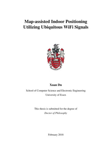
List of Figures1.1Wireless technologies for indoor positioning . . . . . . . . . . . . . . . . .41.2The structure of this thesis . . . . . . . . . . . . . . . . . . . . . . . . . .102.1Illustration of triangulation, a typical geometric positioning technique basedon range measurement. . . . . . . . . . . . . . . . . . . . . . . . . . . . .172.2Plot of Log-distance Path Loss Model. . . . . . . . . . . . . . . . . . . . .182.3Illustration of reference points and access points over indoor map. . . . . .202.4Principle of fingerprinting-based positioning . . . . . . . . . . . . . . . . .212.5Illustration moving trajectory. . . . . . . . . . . . . . . . . . . . . . . . . .282.6Illustration of temporal signal pattern when moving along a trajectory withdifferent device setup. . . . . . . . . . . . . . . . . . . . . . . . . . . . . .2.729Illustration of trajectory options at a junction and the corresponding temporalsignal trend. . . . . . . . . . . . . . . . . . . . . . . . . . . . . . . . . . .302.8Illustration of presenting indoor location using grid. . . . . . . . . . . . . .362.9Illustration of presenting indoor location using topological floor plan. . . .373.1Illustration of the indoor map generation process . . . . . . . . . . . . . .423.2Illustration of the indoor map construction from individual rooms to completed map . . . . . . . . . . . . . . . . . . . . . . . . . . . . . . . . . . .3.343Illustration of the source code of SVG file for a sample map containing 3individual rooms . . . . . . . . . . . . . . . . . . . . . . . . . . . . . . .433.4Illustration of fingerprints of RPi and RPj . . . . . . . . . . . . . . . . . . .473.5Illustration of walls between RP and AP on indoor map . . . . . . . . . . .52
List of Figures3.6Illustration of the cases where two line segments that do not intersect can bedetermined by bounding box. . . . . . . . . . . . . . . . . . . . . . . . . .3.7xii55Illustration of the cases where bounding box check fails (case 5) and twoline segments intersect (case 6). . . . . . . . . . . . . . . . . . . . . . . .563.8Heat map of the RSS observed in the experimental site. . . . . . . . . . . .603.9Heat map of the RSS predicted by the FSPL model. . . . . . . . . . . . . .603.10 Heat map of the RSS predicted by the log-distance path loss model with wallattenuation using different attenuation factor per wall thickness. . . . . . .623.11 CDF of the difference between predicted and observed RSS (dBm) usingdifferent attenuation factor per wall thickness. . . . . . . . . . . . . . . . .633.12 Plots of the number of iteration in PSO to achieve convergence betweenrandom (top) and heuristic (bottom) placement strategy. . . . . . . . . . . .643.13 Plots of the placement results computed by different placement schemes: random and heuristic placement, shown in red triangles and blue dots respectively. 653.14 Plots of CDF of location error distance by heuristic and random schemeusing map-aided placement. . . . . . . . . . . . . . . . . . . . . . . . . .673.15 Plots of CDF of location error distance in heuristic placement using mapaided and no map-aided optimisation model. . . . . . . . . . . . . . . . . .4.1Analysis of WiFi signal observations: occupancy of 195 observed APs withdifferent number of observations (left) and frequency band (right). . . . . .4.26870The RSS observations of VAPs operating in 2.4 GHz (top) and 5 GHz(bottom) frequency band from the same physical AP when moving along acorridor for 25 seconds. . . . . . . . . . . . . . . . . . . . . . . . . . . . .724.3Illustration of pathway map. . . . . . . . . . . . . . . . . . . . . . . . . .734.4Illustration of pathway’s nodes and its adjacency matrix representing theconnectivity between nodes. . . . . . . . . . . . . . . . . . . . . . . . . .744.5Illustration of a path segment where the WiFi signals are collected. . . . . .754.6Illustration of signal patterns processing from raw RSS samples observedfrom APs in one path segment of our experimental site . . . . . . . . . . .80
List of Figuresxiii4.7Illustration of Beacon APs Map at RPs on Path Segments. . . . . . . . . . .834.8RSS of different Beacon AP at RPs along path segments. . . . . . . . . . .834.9Illustration of mapping Beacon APs to reference points based on the signalscollected at our experimental site. . . . . . . . . . . . . . . . . . . . . . .854.10 Illustration of mapping Beacon APs to pathway map based on the signalscollected at our experimental site. . . . . . . . . . . . . . . . . . . . . . .864.11 System architecture of positioning using temporal signal patterns . . . . . .874.12 Illustration of implementation on Android app. . . . . . . . . . . . . . . .904.13 CDF of location error distance using different device setups. . . . . . . . .924.14 CDF of location error distance in different usage scenarios. . . . . . . . . .924.15 Relationship between location error distance and number of Beacon APsgenerated in robust searching scheme. . . . . . . . . . . . . . . . . . . . .934.16 Relationship between location error distance and number of APs observed inrobust searching scheme. . . . . . . . . . . . . . . . . . . . . . . . . . . .944.17 CDF of location error distance using different SCC ratio in selective searching scheme. . . . . . . . . . . . . . . . . . . . . . . . . . . . . . . . . . .954.18 CDF of number of candidate RPs using different SCC ratio in selectivesearching scheme. . . . . . . . . . . . . . . . . . . . . . . . . . . . . . . .954.19 CDF of number of APs used for similarity calculation of positioning usingdifferent SCC ratio in selective searching scheme. . . . . . . . . . . . . . .964.20 CDF of number of APs used for similarity calculation of positioning usingdifferent SCC ratio in selective searching scheme excluding the cases whenno location can be found. . . . . . . . . . . . . . . . . . . . . . . . . . . .964.21 Relationship between location error distance and number of APs used forpositioning in selective searching scheme when SCC ratio is 60%. . . . . .974.22 Plot of bar chart showing the number of APs of raw APs detected and BeaconAPs generated at some of path segments in the experimental site in offlinesite survey. . . . . . . . . . . . . . . . . . . . . . . . . . . . . . . . . . .984.23 CDF of the number of candidate RPs from positioning log. . . . . . . . . .99
List of Figuresxiv5.1Architecture of proposed system . . . . . . . . . . . . . . . . . . . . . . . 1035.2Sequence diagram of proposed system . . . . . . . . . . . . . . . . . . . . 1045.3Format of the data from AP to JPS . . . . . . . . . . . . . . . . . . . . . . 1055.4Enhanced architecture of proposed system . . . . . . . . . . . . . . . . . . 1085.5The Fingerprint Collector app running on the survey MH (left) and thelocation of reference points selected in the experiment (right) . . . . . . . . 1115.6The Web UI displaying the location of multiple MHs (left) and console tocheck the RSS of each individual MH (right) . . . . . . . . . . . . . . . . . 1125.7Comparision of CDF between AP-centred and MH-based system . . . . . . 1135.8Location error distance at each evaluation point by AP-centred and MH-basedsystem . . . . . . . . . . . . . . . . . . . . . . . . . . . . . . . . . . . . . 1145.9Overall energy consumption on MH in MH-based and AP-centred systems . 115
List of Tables2.1Comparison of RF technologies used for indoor positioning . . . . . . . . .163.1Database structure of table that stores the information on indoor map . . . .443.2Constant parameters of the experiment . . . . . . . . . . . . . . . . . . . .594.1Part Of The Notations. . . . . . . . . . . . . . . . . . . . . . . . . . . . .754.2Device Setups . . . . . . . . . . . . . . . . . . . . . . . . . . . . . . . . .91
Symbols and AbbreviationsRoman SymbolsSiRSS values observed from eiTiObservation timestamps from eid0Reference distance in log-distance path loss modeleA path segmentGPathway mapL0RSS at reference distance in log-distance path loss modelMNumber of APs selected as beacons for positioningNNumber of RPs in the interesting areanPath-loss exponent in log-distance path loss modelGreek SymbolsβSignal’s angle of arrival relative to wallλInertia weight of existing velocity in PSOµScaling factor in heuristic placement schemeωAttenuation factor per wall thickness unit
Symbols and Abbreviationsφ0Real-time vector of RSS at unknown locationφiVector of RSS of pre-selected APs at RPiΨRadio map consisting of RSS of all APs at all RPsψk,iRSS of APk at RPiρCoverage overlap ratioϕSignal strength attenuation caused by wallsAcronyms / AbbreviationsAOA Angle Of ArrivalAPAccess PointAPIApplication Programming InterfaceARAcoustic RangingBSSID Basic Service Set IdentifierCDF Cumulative Distribution FunctionCSIChannel State InformationFPFingerprintGPSGlobal Positioning SystemIMU Inertial Measurement UnitIoTInternet of ThingsJPSJoint Positioning ServerKNN K-Nearest Neighboursxvii
Symbols and AbbreviationsLBSLocation-based ServicesLoSLine-of-SightMAC Media Access ControlMHMobile HandheldNICNetwork Interface CardOFDM Orthogonal Frequency-Division MultiplexingPoIPoint of InterestPSOParticle Swarm OptimisationPSTPath Segments TraversalQoEQuality of ExperienceRFRadio FrequencyRFID Radio Frequency IdentificationRPReference PointRSSReceived Signal StrengthRTOF Round-trip Time Of FlightSCC Signal Coverage ConstraintSNR Signal-to-Noise RatioSSID Service Set IdentifierSSPSibling Signal PatternsSVG Scalable Vector Graphicsxviii
Symbols and AbbreviationsTDOA Time Difference Of ArrivalTSPTemporal Signal PatternUIUser InterfaceUWB Ultra-WidebandVAP Virtual Access PointWLAN Wireless Local Area Networksxix
Chapter 1IntroductionIn a wide range of systems with context-aware computing, including the Internet of Things(IoT), wireless sensor networks, mobile social networks and mobile peer-to-peer computing,the indoor location is one of the essential contexts. The enabling technology for them is anaccurate and reliable indoor positioning solution. Indoor positioning attracted many researchefforts from both academia and industry in the past decade, and it has been well studied fromvarious aspects.In this chapter, the background knowledge of indoor positioning is briefly introduced,including the use cases (i.e., application scenarios), technologies which can be used forindoor positioning and the positioning techniques based on different technologies. Then theubiquity of WiFi signals and importance of indoor map are highlighted, which motivated thisresearch work. Next, the problems and challenges of indoor positioning are discussed fromthe aspects of insufficient positioning accuracy and inefficient system deployment. Finally,the contributions of this thesis towards map-assisted indoor positioning utilising ubiquitousWiFi signals are identified.1.1BackgroundThe services based on the context of location information are called location-based services(LBS) and the key enabling technology of LBS is location sensing or positioning (i.e., the
1.1 Background2solution to estimate the location of an object or person in a room, building or in the world)[1]. Based on the fact that human beings spend 90% of their time indoors, with the advanceof mobile devices and great impact of mobile applications (apps) over mobile phones, theLBS for indoor environments is highly desired. However, the very mature satellite-basedpositioning technology such as Global Positioning System (GPS) cannot work indoors sincethe signals from the satellite cannot penetrate well in the indoor environment (i.e., GPS needdirect visibility to satellite) and the positioning accuracy of GPS is not refined enough forindoor scenarios [2]. As a result, an accurate and reliable indoor positioning solution is sodesired to fill the shortage of GPS and is expected to provide the same functionality as theGPS (i.e., provide the location of an object device in real time) [3].Nowadays with the surge of the IoT systems and its broad applications in real life, theindoor location is an important context to achieve various services. The primary functionof positioning is to find a steady location of a stationary or moving device, which is used inthe applications requiring one-off location information, such as mobile social networking orlocation-targeted advertisement. Meanwhile tracking a mobile device instead of obtaininga device’s steady location is also on demand [4]. Tracking is a continuous process ofcomputing a sequence of locations, rather than repeatedly locating the single steady location.Indoor location tracking is a sub-category of indoor positioning and requires typically higherpositioning accuracy [4, 5].The application scenarios of indoor positioning can be summarised as follows. Indoor Navigation for visitors in the large-scale indoor environment, e.g. shoppingmall, exhibition centre and even car park [6, 7]. Smart Home and Ambient Assisted Living, e.g. location-based automated heating orlighting control [8]. Context Awareness Services, e.g. location-based social networking. E-Health Care, e.g. tracking and monitoring the movement of patients [9].
1.1 Background3 Retail Industry, e.g. mobility analysis of customers and targeted retail advertisement inshopping malls.In the last decade, indoor LBS has attracted much research efforts from both academiaand industry [10]. Recent years have seen the emergence of various solutions for indoorpositioning using different technologies and techniques. The technologies range from RadioFrequency (RF) signals such as WiFi [11], Bluetooth [12], UWB (Ultra-Wide Band) [13]and RFID (Radio-Frequency Identification) [14–16] to IMU (Inertial Measurement Unit)[17][18], sound [19, 20], visible light [21][22] and magnetic field [23][24], as shown inFig. 1.1. Meanwhile, many hybrid solutions using multiple technologies are proposed [25].The inertial sensors are commonly used with other technologies to provide prediction orcorrection.There are various positioning techniques used for indoor location estimation. Thewidely used approaches can be classified into two categories: range measurement andfingerprinting [26]. Range measurement techniques obtain the distance between objectdevice and reference beacons (i.e., devices deployed as the infrastructure of positioningsystem) based on the propagation model, such as distance to time of flight model or distanceto signal strength loss model. The location of object device can be worked out using themeasured distance to multiple reference beacons whose locations are known. Fingerprintingtechnique consists of two stages: offline site survey and online positioning, as illustrated inFig. 2.4. Fingerprinting is a common positioning technique used by most received signalstrength (RSS)-based positioning systems. RSS is the measurement of the power observedin a radio signal received. The fingerprint is defined as an RSS vector from multiple signaltransmitters and collected at a location in site survey phase. Successively, the fingerprintsat multiple pre-selected locations are collected to construct the fingerprint database. In thepositioning phase, given an RSS vector observed at an unknown location, which is comparedwith the fingerprints in the fingerprint database, the associated location of the best-matchedfingerprint is estimated as the location of the observed RSS vector [27–29]. The moredetailed description of WiFi-based positioning and approaches to estimating indoor locationare provided in Chapter 2.
1.2 Motivation and Objectives1.24Motivation and ObjectivesAmong existing technologies, the use of WiFi is a popular approach to bring indoor positioning into practice, because WiFi access points (AP) are already deployed extensively inmost public places like hospital and shopping mall and most off-the-shelf mobile devices arealready equipped with WiFi communication modules [30, 31]. In the WiFi-based positioning,the APs act as the natural beacons for positioning and the off-the-shelf mobile devices arethe targeted positioning object. The wide deployment of WiFi infrastructure and the ubiquityof WiFi-integrated mobile devices have provided a massive opportunity for indoor LBS.Fig. 1.1 Wireless technologies for indoor positioningThe positioning systems and LBS need to clarify the following questions: how to expresslocations, how to obtain a location and then how to display a location in the user interface(UI). For the outdoor environment, location can be expressed by latitude and longitude of thegeographic coordinate system and map platforms such as Google Map and Open Street Mapcan provide mature graphical presentation interface and sufficient geographic data to indicatethe required outdoor locations [32–34]. While for the multiple-storey indoor space, neitherthe geographic coordinate system nor graphical map platform exists. Thus, an appropriatesetup of indoor coordinate system and presentation of the indoor environment, e.g. indoorlocation and indoor map, are essential for indoor positioning systems.
1.2 Motivation and Objectives5We believe the indoor map will become pervasive and will be a crucial componentto bring indoor positioning into practice. Firstly, the widely-used Google Map was justlaunched in 2005 to provide the mapping of the outdoor environment, and nowadays almostall the location-based services are based on Google Map or similar platforms [32]. With thedevelopment of the Internet of Things, Smart Cities, Ambient Assisted Living and so on, theindoor location information is becoming an important context and mapping of indoor spaceis on demand [4, 8, 9]. Therefore, we believe the indoor map will be developed promptly,and a giant platform like Google Map but for the indoor environment may appear very soon.Some indoor map systems have been available in the market, but the functionality is stilllimited. Secondly, in the last decade, researchers proposed many indoor positioning solutionsby obtaining and fusing various data, including different RF signals, the inertial sensor,acoustic data, vision data and indoor map. Among those data, apart from the indoor map theavailability and quality of them are dependent on the positioning technology. However, theindoor map is always available and can work with any positioning technology [27]. Thirdly,to support tracking or navigation services, the map is an essential prerequisite and has beencommonly used in outdoor in-car navigation [35].Thus, the ubiquity of WiFi and the critical role of the indoor map for indoor positioningmotivate this thesis to investigate the indoor positioning problem through the usage of theubiquitous WiFi signals and information from the indoor map. The objective of this thesis isto improve the positioning accuracy and deployment efficiency of indoor positioning systemfrom three aspects, which is summarised as follows.1. Investigate the data structure to describe the information available in the indoor environment and the approach to implement it as an indoor map.2. Investigate the ubiquitous WiFi signals and its opportunities to improve the performance of indoor positioning, especially in conjunction with information obtained fromthe indoor map.3. Investigate the role access point plays in WiFi-based indoor positioning and its opportunities to assist positioning.
1.3 Problems and Challenges1.36Problems and ChallengesThe essential and inevitable problem for indoor positioning is the complex indoor environment, characterised by non-line-of-sight (LoS) and signal fluctuation caused by dynamicenvironmental changes such as people and furniture. For positioning system based on rangemeasurement, to predict the distance between reference beacon and target device accurately,the essential condition is modelling the radio propagation correctly. However, it is verydifficult to model the signal propagation in the indoor environment due to a variety of interference. Most importantly, the low availability of LoS path is one critical obstacle, whichmake
based positioning. Secondly, the patterns of WiFi signals are observed and deeply analysed from sibling and spatial aspects in conjunction with pathway map from indoor map to address the problem of inconsistent WiFi signal observations. The sibling and spatial signal patterns are used to improve both positioning accuracy and efficiency.