Transcription
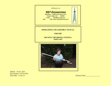
A PRODUCT OFRST ENGINEERINGMail/Ship: 13993 Downwind CourtGrass Valley gineering.comOPERATIONS AND ASSEMBLY MANUALFOR THERST-8710 VHF DIPOLE ANTENNASORTA-KITEdition: 14 Jan 2014Part Number: 4-8710-8101Print Date: 14 Jan 14Purchase Date:
A.INTRODUCTIONWelcome to the RST line of Sorta-Kits -- it’s sort-a kit, and sort-a-not-a kit. In an attempt to keep your cost of our products to a minimum, aSorta-Kit is supplied with all of the sort-a critical components in the kit but the sorta-a-not-a critical components that add bulk and weight toyour shipping costs are left for you to obtain locally. Typically these parts are things that you will be able to find at any reasonably well stockedhardware or "hobby electronics shack" store. These locally obtained materials may need simple modifications like drilling, sawing, painting andother typical "home shop" operations.The RST-8710 VHF Vertical Dipole antenna is one of these sorta-kits. All the electronic parts are included with the RST-8710 to make oneantenna for any 15 MHz segment of the VHF COM aircraft band (118-137 MHz), or the amateur radio 2-meter (144-148 MHz) band.The basic antenna is made of copper tape and coaxial cable (RST supplied) mounted on a wooden dowel and enclosed in a PVC water pipeenclosure (you obtain locally). After assembly in accordance with our instructions, the antenna is weather and water proof as well as structurallyrobust.The RST-8710 antenna may be constructed for any center frequency from 125 MHz through 500 MHz using the materials supplied by a simplefrequency scaling routine. The antenna length as well as number of choke coil turns is a linear function of frequency and may be scaled directly– the higher the frequency, the shorter the antenna and the less choke turns required.For center frequencies below 125 MHz RST suggests that you construct the antenna using #14 copper wire ("Romex" house wire) with a smallreduction in bandwidth and purchase a longer length of RG-174 coax cable from any good electronics supply house (Mouser, Digi-Key orJameco).B.WARRANTYThe Sorta-Kit warranty is the same as the regular kit warranty. We guarantee that the kit will meet the published specifications and that thecomponents supplied and specified will meet those specifications including parts and labor for one year.We guarantee the components for an additional year (without labor) if the defective component is returned to RST Engineering postpaid. Ingeneral, for a Sorta-Kit we will ask that you phone us first and describe the nature of the failure. If we determine that the component is in factdefective by the phone call we will usually (but do not obligate ourselves to) send a replacement component without the expense of your havingto return the defective part.We think that it is obvious that any component that has been subjected to excessive strain not normal in the service contemplated is not coveredby this warranty. In particular, overtemperature during soldering, improper mechanical assembly, and use of the product beyond the scope of the4-8710-8101 Rev:AVertical DipoleEdition: 06 Jan 2012Page 1 of 20
instructions in this manual constitute abuse of the product and voids the warranty. No other warranty is expressed or implied, including warrantyof merchantability or fitness of purpose.C.TEST AND CALIBRATIONThe Vertical Dipole needs no calibration prior to use. To test the Vertical Dipole requires a source of RF energy (a transmitter) and a StandingWave Bridge (VSWR Bridge or Bidirectional Wattmeter) connected as shown on drawing 871-3950 in section H of this manual. As shown inthe VSWR curves in section H, the return loss should be below 1.5:1 (4% or 14 dB) at the frequency for which the dipole is cut and risesymmetrically on both sides. The VSWR test is optional, but it gives a confidence and correlation factor to the field test below.If necessary, slight decreases in length (to raise the resonant frequency) or increases in length (to lower the resonant frequency) may beaccomplished by cutting a short length equally from both dipole elements with a hobby knife or razor trimming blade. To lower the frequency,add short lengths of tape to the elements, cut the short length of tape twice as long as you think necessary, then overlap the tape elements withthe tape sections and solder the junction of the short added tape piece with the tape element.We STRONGLY recommend that a field test be performed on the antenna prior to final assembly. The very best test is to use a known goodomnidirectional antenna on your transmitter and a known good receiver at some distance from the antenna. Make a test transmission and notethe signal strength on the receiver. Replace the known good antenna with your newly constructed Vertical Dipole antenna and make a secondtransmission. The field strength on the receiver should be equal to or greater than the field strength with the known good antenna.(Note: be sure that you only hold the Vertical Dipole in position for this test below the matching coil section. Holding the antenna nearthe elements, especially with metallic fasteners, will detune the elements and render this field test useless.)D.THEORY OF OPERATIONThe Vertical Dipole antenna is comprised of two major sections – the antenna elements and the coaxial matching coil.The antenna elements are the classic dipole-in-space design with a rigid wooden rod supporting the elements as well as providing a coil form forthe matching coil. Good dry varnished hardwood is an excellent low-loss insulating material as well as a mechanically rigid structural material.The general problem with a vertical dipole is the proximity of the coaxial feedline cable to the bottom element of the dipole. By using a selfresonant coil at the base of the dipole, the coax cable can be isolated from the dipole elements.4-8710-8101 Rev:AVertical DipoleEdition: 06 Jan 2012Page 2 of 20
This antenna may be constructed for "conformal" or "plastic airplane" use with the copper tape attached to a flat piece(s) of flexible plasticinstead of a rigid hardwood dowel and the coil wound on any material (wood, plastic, etc.) of the proper 3/8" diameter. In this way, the antennamay be "bent" around other non-metallic structures to conform to the shape of the airframe.At any rate, the self-resonant coil is the basis for the decoupling and matching of the coaxial cable to the antenna elements. Any coil iscomprised of two parts – the inductance of the "wire" due to the number of turns of wire in the coil and the capacitance between each of the turnsof wire in the coil. When the inductive reactance of the coil equals the capacitive reactance of the coil, the coil is said to be "self-resonant.” Thissimply means that we have come to the frequency where the coil is parallel resonant with the inductance and the self-capacitance of the turns ofthe coil. Since a parallel resonant circuit provides a very high impedance, any energy contained on one side of the coil will not be coupled to theother side of the coil.The coil "wire" is simply the outer shield ("braid") of the coaxial cable used as a feedline. We have chosen the number of turns of this coaxialcable to be self-resonant at the operating frequency of the antenna. The power is delivered to the antenna by the center conductor of the coax,which is isolated from the outer surface of the braid by the braid itself. Thus, the power is delivered to the antenna via the antenna centerconductor, but any reradiation of the power down the outer shield or braid of the coax cable is prevented from going back to the transmitter bythe self-resonant properties of the braid wound into a coil.E.INSTALLATIONThe base-station configuration of the RST-8710 antenna must be installed with any metallic clamping devices (hose clamps, metal wire clamps,conduit clamps, etc.) installed BELOW the matching coil area inside the PVC pipe. If you install the decal as shown in the construction section,then you have an easy reference to the location of the coil area inside the pipe.Drawing 871-3951 (attached at the end of this manual) shows several ways to mount the antenna as a base station antenna.A. Drill a small pilot hole into the top PVC end cap and thread a metal eyelet into the end cap. Use some sort of sealant (RTV orsilicone sealant) on the threads to keep the inside of the pipe hermetically sealed. This method of mounting is used primarily in aportable/emergency environment where a string is looped around a tall tree branch and the antenna hauled up by the string. If you are inthe field and need to make an emergency mount without the eyelet, simply use a tight knot on the pipe side of the top PVC end cap andhaul the antenna up by the flange on the end cap.B. This method of mounting supposes that you are going to use metal clamps (radiator or worm clamps) to fasten the antenna to anothermast. In this method of mounting, cut the long PVC pipe 2" shorter than the directions say, glue a ½" PVC slip coupling to the bottom ofthe mast, and then glue a 1½" short PVC pipe section into the slip coupling. Install the bottom end cap in accordance with the standarddirections.4-8710-8101 Rev:AVertical DipoleEdition: 06 Jan 2012Page 3 of 20
C. This is similar to the "B" method of mounting, but instead of a slip coupling, a ½" PVC Tee fitting is glued onto the long pipe, thenthe short pipe glued into the Tee. A short (¾" or so) pipe section couples the Tee to a slip-threaded Ell. This method is used where youhave a ½" pipe thread already on your antenna mast and you wish to make the mounting onto this pipe thread. (NOTE: the antenna is nolonger hermetically sealed with this option of mounting.)Installation of this antenna into a composite structure (i.e., a "plastic airplane") may be done by any one of a number of methods. Certainly therigid wooden dowel may be used if you wish, but it is also possible to install the tape onto a thin piece of flexible plastic or fiberglass, or onto theaircraft structure directly, if you choose. The only warning that RST can give is that the matching coil be wound on the proper diameter formAND that it be wound at a distance from the center of the dipole as measured and shown in the construction plans. The distance between thecoax cable and the bottom of the antenna is NOT critical, so long as you understand that the braid of the coax is soldered to the BOTTOMelement of the dipole at the dipole center.In both the base station configuration AND the composite configuration, it is ABSOLUTELY necessary to use 50 coaxial cable between theantenna and the transmitter. Using "cable TV" coax (70 ) will NOT make the antenna perform as designed.F.OPERATIONThere are no controls or other adjustments on the RST-8710 antenna. After the antenna has gone through installation and test, it should requireno adjustment throughout its lifetime.G.CONSTRUCTIONThe construction steps below are geared towards the construction of a base station version of this antenna. If you are going to use the antenna ina composite structure ("plastic airplane, etc.) then you may follow the general ideas below, substituting your own personal materials and methodsfor the specific steps that follow.1.Items Required But Not Supplieda.4-8710-8101 Rev:AWooden dowel material, hardwood 3/8" diameter. Length as determined by formula. (Note: Hardware stores generally do notstock 3/8" dowel material longer than 48" long.)Alternatively, use plastic pipe or rigid plastic tubing 3/8" diameter which comes in lengths longer than 48", but is not as readilyavailable.Vertical DipoleEdition: 06 Jan 2012Page 4 of 20
2.b.PVC plastic pipe, schedule 40 (white), ½" size. Length 4" longer than the dowel.c.PVC plastic end caps, schedule 40 (white), ½" size (quantity 2).d.Shop materials: Drill, 1/8" bit, 3/8" bit, saw, soldering iron & solder, pipe glue.AssemblyFor your own reference in the following steps, you may wish to fill out this table of dimensions calculated from drawing 871-2950 inSection H of this manual. Alternately, the Excel spreadsheet supplied with this manual will do these calculations for you:DimensionCenter Frequency (MHz)Tape LengthHole LengthAntenna LengthCoil LengthNumber of TurnsDowel Lengtha.ReferenceValueFTLHLALCL#DLCut two identical pieces of tape to the length for your chosen frequency as shown in drawing 871-2950 in Section H of thismanual (dimension TL).Note that the creases in the tape at the folds may be taken out with a blunt instrument (like the handle of a hobby knife or afingernail) and a hard surface (like a kitchen counter). Gently burnish the tape creases out with the blunt instrument and with thetape resting on the hard surface. If you choose not to burnish the creases out, it will NOT affect the performance of the antenna.You may also burnish out the creases on the hardwood dowel after you install the tape onto the dowel.4-8710-8101 Rev:AVertical DipoleEdition: 06 Jan 2012Page 5 of 20
b.Cut the wooden dowel to length as shown on drawing 871-2950 (dimension DL). Drill the three 1/8" holes in the dowel as shown.Varnish or use sanding sealer to seal the wood surface. (We use Deft interior finish sealer at RST.)c.Cut the PVC pipe to 4" longer than the dowel length (DL) as cut in step b. (See mounting instructions in "Installation" beforecutting pipe.)d.Drill a hole in one of the plastic end caps 3/8" diameter in the center as shown on drawing 871-2950 in section H of this manual.(Note – for better sealing, you may wish to countersink the outside of the end cap so that the BNC connector fits down into thecountersink. Countersinking the outside of the end cap also makes it a little easier to start the nut onto the BNC connector threadsin a later step.)e.Remove the covering from the self-sticky back of the tape. Install the tape onto the dowel as shown on drawing 871-2950. Besure to leave a ¼" gap between the two elements and the two elements equidistant from the 1/8" hole at dimension HL. Cut theV-notch into the tape near hole HL as shown in photo 5.a.f.Insert one end of the RG-174 coaxial cable through the hole at dimension HL so that the coax cable protrudes through the coppertape side of the hole about a foot. Strip the end of the coax protruding through the hole in the following manner:4-8710-8101 Rev:A1)Remove ½" of the black outer sheath. Try to cut or nick the braid as little as possible when removing the plastic outersheath.2)At the base of the exposed braid, where the braid exits the stripped sheath, move the braid with an icepick or other sharppointed instrument so that it forms a hole in the braid big enough to pull the center insulator through3)Pull the center insulator through this hole at the base of the braid so that you have ½" of braid with nothing in the centerand ½" of center insulator with center conductor inside.4)Strip the center insulator back ¼" so that there is ¼" of bare center conductor exposed.Vertical DipoleEdition: 06 Jan 2012Page 6 of 20
5)Pull the coax back down into the hole so that only the braid and center conductor still protrude through the hole. Connectthe coaxial cable by soldering the coax cable to the copper tape antenna elements as shown on drawing 871-2951.6)Be sure that the center conductor of the coax is soldered to the TOP element, and the braid is soldered to the BOTTOMelement.7)Be very careful when soldering the coax to the copper tape that you do not overheat the coax and melt the centerinsulation. You may wish to use an ohmmeter to check that there is an open circuit between the antenna elements afteryou complete the soldering procedure.g.Route the coax straight down the wooden dowel on the side of the dowel opposite that of the copper tape and pass the free end ofthe coax through the top remaining hole in the dowel (dimension AL). Using the number of turns of coax calculated in drawing8710-2950, wind the correct number of turns of coax onto the dowel. Wind the turns as close together as possible. Pass the freeend of the coax cable through the bottom hole (dimension CL). (If you didn’t wind the coax coil turns very close together, thiswill be a very tight fit.)h.Twist the coax-coil turns so that the coax is wound tightly around the dowel. Take any slack in the coil up by pulling the excesscoax through the bottom hole in the dowel.i.Cut the free end of the coaxial cable so that there is 6" of cable remaining below the bottom of the dowel. Strip the outer blacksheath from the end of the coax so that there is 1" of braid exposed. Make a hole in the braid and pull the center insulator andconductor through this hole in the braid in a similar manner as step f above.j.Strip the insulation from the center conductor so that there is about ¼" of center conductor exposed.k.Install the BNC female chassis mount connector through the drilled hole in the end cap so that the body of the connector is on theOUTside of the cap. Install a solder lug under the nut securing the connector to the cap. Bend the solder lug up away from theplastic body of the end cap as much as possible. Note – if you want this antenna hermetically sealed, use a little silicone sealanton the outside surface of the pipe cap when installing the connector.4-8710-8101 Rev:AVertical DipoleEdition: 06 Jan 2012Page 7 of 20
l.Solder the center conductor of the coax cable coming from the bottom of the pipe to the center pin of the BNC coax connector.Solder the braid of the coax to the solder lug of the BNC connector. Make this last connection with a hot iron and as fast aspossible to avoid melting the plastic pipe cap body.m.This is the last opportunity you will have to test your antenna before it is sealed. Please perform any testing and last-minuteadjustments you want to make at this time.n.Carefully push the dowel-antenna into the pipe from the bottom as far as possible without stressing the coax cable - connectorjoint. The top of the dowel should be ½" above the top of the pipe.o.Install the 3/8" vinyl grommet over the top of the dowel so that the top of the grommet and the top of the dowel are flush with oneanother. Using a small screwdriver or other small flat tool, work the grommet-dowel assembly back down into the pipe so thatthe tops of the dowel, grommet and pipe are all the same. Note – the grommet was deliberately chosen slightly oversize to makea tight "squeeze" fit for vibration resistance.p.Place the "Use Clamps Below This Point" decal to the pipe so that the line on the decal is aligned with the bottom of the coilinside the pipe. Place the other two decals on the pipe, one at the midpoint and the other 1" below the top of the pipe. If desired,you may coat the decals with a thin coat of varnish or sealer to keep weather from harming the decals.q.Use PVC cement to attach the top and the bottom pipe caps to the pipe. When installing the bottom cap, get as much of the coaxinto the bottom of the pipe as possible before applying the cement.r.This completes the construction of your antenna.4-8710-8101 Rev:AVertical DipoleEdition: 06 Jan 2012Page 8 of 20
H.DRAWINGS, PARTS LISTS AND APPLICATION NOTES1.Parts ListMaster Parts ListQty.Part Number1 1-1201-15071 1-2120-30011* 1-2501-123796 1-6031-17401 2-4201-10371 4-0001-80001 4-8710-0100RST-8710 Vertical Dipole9-8710-0902Part NamePart DetailAntenna tape, copperConn, bncLug, solder, flatCable, coaxGrommetOwner's ManualRST-87101/2" x 0.001" x 48"female chassis, UG1094/U3/8"RG-1740.37"CDROM Rev:BDecal (3-across)*This solder lug may be supplied with the BNC connector (1-2120-3001)Lengths given in inches.2.Manufacturing Dimensions (871-2950)3.VSWR Curves and Test Setup (871-3950)4.Mounting Methods (871-3951)4-8710-8101 Rev:AVertical DipoleEdition: 06 Jan 2012Page 9 of 20
#14 copper wire1/2" wide copper tapeELDLCLALHL3/8" woodendowelTop1/8" diameter hole(3 places)Lengths in inches calculated for anantenna at frequency "F" in MHz.½" PVCEnd Cap3/8 diameter holein center of capEL 2690 / F (for copper tape)EL 2745 / F (for #14 wire)CL HL EL 0.2"AL EL HL 0.1CL 550 / FCut notches in copper tape athole to provide clearance forsoldering coax cable wires.Number of coil turns 4750 / FCLDL AL CLSample calculation for a resonant frequency of 125.0 MHz.:EL 21.5"CL 4.4"HL 21.7"# of turns 38AL 43.3"4-8710-8101 Rev:A Vertical DipoleScale:RST 8710 AntennaManufacturing DimensionsNTS Approved by:Date: 07 Jan '14 RST EngineeringDL 47.7"Edition: 06 Jan 201213993 Downwind Court Grass Valley CA 95945530.272.2203tech@rst-engr.comDrawn by: OWJRev:BDrawing #8710-2950sheet 1 of 1Page 10 of 20
3:12.5:1VSWRIf necessary, hold antenna inthis area only with metal clamps.This antenna is cutfor 125 MHz., the lowlimit for a 48" longantenna and coversthe low end of theaircraft com band.This antenna is cutfor 146 MHz., thecenter of the amateurradio 2-meter bandSpecificationLimitSpecificationLimit2:11.5:150 ohm coax cable - TypicalMeasured PerformanceVSWR Frequency in Megahertz50 ohm coax cable - TransmitterScale:RST 8710 AntennaVSWR Curves & Test SetupNTS Approved by:Date: 07 Jan '14 RST Engineering4-8710-8101 Rev:AVertical DipoleEdition: 06 Jan 201213993 Downwind Court Grass Valley CA 95945530.272.2203tech@rst-engr.comDrawn by: OWJRev:BDrawing #8710-3950sheet 1 of 1Page 11 of 20
OPTION AAdd threadedmetal hook intotop PVC endcapBasic "As Constructed"AntennaOPTION BAdd PVC slipcoupling andextension pipebelow coil areaAddedAddedScale:OPTION CAdd PVC TEEand right anglethreaded adapterbelow coil areaRST 8710 AntennaOptional Mounting MethodsNTS Approved by:Date: 07 Jan '14 RST Engineering4-8710-8101 Rev:AVertical DipoleEdition: 06 Jan 201213993 Downwind Court Grass Valley CA 95945530.272.2203tech@rst-engr.comDrawn by: OWJRev:BDrawing #8710-3951sheet 1 of 1Page 12 of 20
5.Photo Identificationa.Connecting the coax to the copper elementsb.Construction of the coilc.Connecting the coax to the BNC connectord.Using RTV (silicone seal) to immobilize the solder connectionse.The assembled antenna before putting it into the plastic pipef.The completely assembled antenna (with Option C mounting method)g.Close-up of Option C mounting method4-8710-8101 Rev:AVertical DipoleEdition: 06 Jan 2012Page 13 of 20
4-8710-8101 Rev:AVertical DipoleEdition: 06 Jan 2012Page 14 of 20
4-8710-8101 Rev:AVertical DipoleEdition: 06 Jan 2012Page 15 of 20
4-8710-8101 Rev:AVertical DipoleEdition: 06 Jan 2012Page 16 of 20
4-8710-8101 Rev:AVertical DipoleEdition: 06 Jan 2012Page 17 of 20
4-8710-8101 Rev:AVertical DipoleEdition: 06 Jan 2012Page 18 of 20
4-8710-8101 Rev:AVertical DipoleEdition: 06 Jan 2012Page 19 of 20
4-8710-8101 Rev:AVertical DipoleEdition: 06 Jan 2012Page 20 of 20
NOTES:
mast. In this method of mounting, cut the long PVC pipe 2" shorter than the directions say, glue a ½" PVC slip coupling to the bottom of the mast, and then glue a 1½" short PVC pipe section into the slip coupling. Install the b
