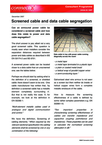
Transcription
2012 EDITIONNexans Olex New Zealand Power Cable Cataloguewww.olex.co.nzAUCKLAND BRANCHCHRISTCHURCH BRANCH69 Paraite RoadBell BlockNew PlymouthNew Zealand105 Hugo Johnston DrivePenroseAuckland 1061New Zealand35 Phillips StreetLinwoodChristchurchNew ZealandPHONE0800 OLEX NZEMAILtechnical.olexnz@nexans.com2012 EDITIONHEAD OFFICENexans Olex New ZealandPower Cable Catalogue
CATALOGUE CONTENTSNexans Olex New ZealandPower Cable Catalogue
Table of ContentsTABLE OF CONTENTSPAGESection One - Introduction1Company Profile2Technical Service and Support3Quality Assurance4Section Two - General Technical Information1Installation Information2Installation Methods4Single Core Cables in Parallel7Rating Factors8Bending Radii and Duct Sizes10Pulling Tension11Short Circuit Ratings12Conductor Short Circuit Ratings13Conductor Max DC Resistances14Conductor Dimensions15Wire and Cable Size Comparison16Notes18Section Three – Low Voltage CablesNotesExplanatory Information13- Construction4- Current Ratings5- Rating Factors6- Voltage Drops8- Selection Procedures10-Minimum Copper Earthing Conductor Size11Product Sheets (See Section Three Contents Page 1 for Product Sheets Listing)12Tabulated Electrical Data- Current Ratings76- Voltage Drops92- AC Resistances94- Reactances96- Volt Drop Graphs98
Table of ContentsTABLE OF CONTENTS (CONT.)PAGESection Four – Medium Voltage TR-XLPE CablesExplanatory Information- Construction2- Screen Designs4- Testing5- Test Voltage Levels6- Installation Tests7-Current Ratings9- Rating FactorsProduct Sheets (See Section Four Contents Page 1 for Product Sheets Listing)Notes121- Thermal Characteristics2- Electrical Characteristics4- Physical and Mechanical Characteristics5- Bare Overhead Conductors7Product Sheets (See Section Five Contents Page 1 for Product Sheets Listing)Notes1056Section Five – AerialsExplanatory Information1822
INTRODUCTION
IntroductionSection OneSECTION ONE - INTRODUCTIONPAGECompany Profile2Technical Service and Support3Quality Assurance4Section 1, Page 1
Section OneIntroductionCOMPANY PROFILEPower cables have been manufactured and tested at the Nexans Olex Bell Block factory on the outskirts of New Plymouthfor more than 40 years. Established in 1967 as a joint venture between Tolley and Son and Canada Wire and CableCompany of Toronto, it was known as Canzac until 1984 when it was purchased by the Pacific Dunlop Group, one ofAustralia's largest international companies, and became part of the Pacific Dunlop Cables Group. In 1999 Olex Cables(New Zealand), together with other Pacific Dunlop Cables Group businesses, was bought by a Management BuyoutConsortium (MBO), and then was known as Olex New Zealand Limited, a Subsidiary of Olex Holdings Pty Limited. It wasin 2006 that the MBO consortium sold its shares in Olex Holdings to Nexans. The acquisition by Nexans became effectivein December 2006.Nexans Olex is a world leader in cable technology and production and has manufacturing facilities in New Plymouth andMelbourne. Each site has been designed to efficiently manufacture specific product groups to cater for the needs of theindustry. With over 40 years experience behind it, Nexans Olex employs more than 1500 people and has the financialbacking, the expertise and the commitment to maintain and expand its position as a world leader in cable technology,manufacturing and installation.At its New Plymouth factory, Nexans Olex produces a wide range of electrical power cables, ranging from building wiresand control cables to power cables with rated voltages up to 35 kV. Complementing this range is a wide selection of powerand data/communications cables manufactured by other Nexans factories around the world.Nexans Olex has proven its expertise and commitment to quality and service in fulfilling contracts in many New Zealandand international markets. The company has a strong commitment to further growth and expansion internationally.With this background, Nexans Olex is well placed to retain its leading role in terms of customer service, quality andresearch.Section 1, Page 2
IntroductionSection OneTECHNICAL SERVICE AND SUPPORTNexans Olex’s extensive technical resources mean that a cable can be designed to meet the exact needs of a customer.The standard range of cables may contain a cable that will do the required job, but Nexans Olex's commitment is to ensurethat a cable's capabilities meet the precise requirements of the installation.This may mean that a standard cable needs to be modified for optimum performance or have a new feature added - this isa normal part of the Nexans Olex service.Nexans Olex's technical support does not finish with the successful design and production of the cable. In addition, acomprehensive cable advisory service is also offered. Technical staff are available to assist in providing expert solutions toall types of cable problems and inquiries.Section 1, Page 3
Section OneIntroductionQUALITY ASSURANCEFor Nexans Olex, quality means the ability to satisfy the needs of its customers, its employees and the proprietors.Accordingly, Nexans Olex recognises the nature of these relationships and has linked these three essential needs togetherto form a policy cornerstone.Quality is important as its inherent cost effectiveness contributes to the competitiveness of the company's products andservices, and to profitability and growth. The contribution of every member of the Nexans Olex team to the quality ofproducts, to customer service and the company is essential to the goal of excellence through quality.Nexans Olex has developed and implemented Quality Management using the AS/NZS/ISO 9001 standard as the model forquality assurance and the criteria for third party accreditation through Bureau Veritas Certification. There is flexibility tomerge additional customer requirements into the routine Quality Verification Plans.Whilst each company within Nexans is individually responsible for the quality of its own cable products and services, eachhas achieved third party accreditation to at least the ISO 9001 level. This parity in quality management provides NexansOlex with the flexibility to access the entire product ranges of all companies within Nexans without compromising its ownquality management standardsNexans Olex offers only brand name accessory products from suppliers with a history of product quality and service.When required, details of the suppliers' quality systems and any third party accreditation to recognised Quality AssuranceStandards can be supplied.Section 1, Page 4
GENERAL TECHNICALINFORMATION
General Technical InformationSection TwoSECTION TWO - GENERAL TECHNICALINFORMATIONPAGEInstallation Information2Installation Methods4Single Core Cables in Parallel7Rating Factors8Bending Radii and Duct Sizes10Pulling Tension11Short Circuit Ratings12Conductor Short Circuit Ratings13Conductor Max DC Resistances14Conductor Dimensions15Wire and Cable Size Comparison16Notes18Section 2, Page 1
Section TwoGeneral Technical InformationINSTALLATION INFORMATIONGeneralAll cables must be installed to comply with the latest New Zealand Wiring Regulations.MoistureNexans Olex cables are manufactured in conditions that exclude moisture, as it is difficult to remove from a finished cable.It is important that precautions are taken during installation to ensure that moisture is not permitted to enter the cable. Cutends or opened areas must be protected from moisture at all times, including during pulling in. Cables, after cutting, mustbe re-sealed for storage, by an effective method such as a heat shrinkable cable cap.Single Core CablesThe following points relating to single core cables should be noted:1. Single core cables carrying the phase currents of a single circuit must be installed as closely as possible together, tominimise inductive reactance and voltage drop. The preferred formation for three phase conductors is a "trefoil" orcloverleaf pattern although flat touching formation is also acceptable. Sheaths should be in contact with one another ineither case.2. A single core cable generates an alternating magnetic field around itself which can cause large increases in voltage dropand power loss due to "transformer effect" when ferrous metal (iron and steel) is allowed to encircle the cable. Steelracking or ladder will not induce this effect, but the following must be observed:a. Cable cleats may be of wood, plastic, or non-ferrous metal but steel saddles should not be used on single cores.b. Where three single phase cables pass through a steel bulkhead, they must all pass through the same hole. Whereglanding is required, it is usual to cut out a panel and replace this with a non-ferrous (metal or plastic) plate in which thethree or four glands are mounted.Cable SupportUnder fault conditions, single core cables used as phase conductors in a multi-phase system may be subjected to largeelectromechanical forces which tend to drive them apart. Generally, properly designed cleats spaced at 1500 mm intervalswill provide adequate support to the cable under normal operating conditions. However special consideration may berequired if fault currents in excess of 15 kA are anticipated.Green GooAlso known as “Green Slime”, this phenomenon is characterised by the appearance of a sticky green exudate leaking outof PVC-insulated wiring at locations such as switches, hot points and light fittings. It is a common occurrence in bothAustralia and New Zealand.The green goo problem is predominantly associated with older (25 years) TPS-type cables operating in a warmenvironment. The exudate comprises a plasticiser that has migrated out of the PVC insulation, coloured due to reactionwith the copper conductor, and that has subsequently travelled - by capillary action and/or gravity – along the conductor toemerge at a termination point.Due to its stickiness and unsightly colour, the goo has a high nuisance value, however it poses no significant healthhazard. It may be cleaned from surfaces by wiping with a rag soaked in a petroleum- or alcohol-based solvent (such asmeths).The long-term consequence of the exudate is that it represents a de-plasticising of the insulation, meaning that as theprocess continues, the PVC will eventually become brittle, and crack.Section 2, Page 2
General Technical InformationSection TwoINSTALLATION INFORMATION (CONT.)TPS Cables in Polystyrene Thermal InsulationWith the increasing use of polystyrene block insulation in houses and caravans, it is important to explain the potentialproblem that arises when PVC sheathed and insulated cables come into direct contact with this material.The plasticiser that is added to PVC to make it flexible, has a tendency to migrate out of the PVC and into materials withwhich it is in contact, particularly where those materials – such as polystyrene and polyurethane - have a great affinity forthe plasticiser. This will lead to the PVCs becoming progressively harder and more brittle, while in contrast the polystyrenewill appear to “melt” as it absorbs the plasticiser.The rate of migration is dependent upon the relative thickness of the materials, the temperature, and the amount of surfacearea in direct contact. Accordingly, the rate of deterioration of the PVC cable can vary considerably under differentcircumstances.To mitigate the problem it is recommended that the amount of direct contact between the cable and the polystyrene bereduced as much as possible. Effective ways of achieving this include positioning the cable with an air gap between thesheath and the polystyrene, or installing the cable within a rigid PVC or PE conduit.UV ResistanceMany polymers, due to their molecular structure, are prone to attack by UV radiation, and because of this will degrade uponcontinued exposure to sunlight, eventually cracking and splitting. The polyolefin family of materials, such as PE (includingXLPE or X-90) and PP is particularly susceptible to deterioration in this manner. PVC is also at risk but noticeably less so,partly because of its structure but also due to the mitigating effects of the fillers, plasticisers and stabilisers that arecompounded with it.A simple, effective and cheap material that can be added to plastic compounds to absorb UV radiation is carbon black.However, while this approach is appropriate for sheathing materials, it is not necessarily so for insulating materials as thecarbon masks the core colour.Nexans Olex recommends that the insulation of its cables be protected (covered) from solar radiation at all times, except inthose instances where the material has been deliberately modified to guard against the effects of UV, eg, Aerial BundledCables (ABC). This covering may simply be the sheath of the cable.Lugs and LinksStranded compacted conductors, either round or sector shaped, must have lugs and links fitted that are manufactured forthe same nominal cross-sectional area as the conductor. For example, a 150 mm2 conductor must have a 150 mm2 lug orlink fitted, and the correct dies, as stated by the manufacturer, used to compress it.Although the lug or link will appear to be loose on the conductor, this is simply because the initial compression of the jointhas already taken place during the manufacture of the conductor; the final compression of the joint will be correct.If, for example, a 120 mm2 lug or link was fitted to a 150 mm2 conductor, the joint would be over-compressed and likely tofail in service. In addition, the smaller lug in itself would be unable to carry the same maximum current as the largerconductor, particularly with respect to fault currents.Nexans Olex manufactures conductors to be compatible with lugs and links normally available in New Zealand.Section 2, Page 3
Section TwoGeneral Technical InformationINSTALLATION METHODSFigure 2.1 Graphical Representations of Methods of Installationa) EnclosedCables installed in conduit ortrunking or other similarenclosure.b) Completely Surrounded by Thermal Insul
www.olex.co.nz Power Cable Catalogue Nexans Olex New Zealand 2012 EDITION Nexans Olex New Zealand Power Cable Catalogue 2012 EDITION. CATALOGUE CONTENTS Power Cable Catalogue Nexans Olex New Zealand. Table of Contents TABLE OF CONTENTS PAGE Section One - Introduction 1 . Company Profile 2 . Technical Service and Support 3 . Quality Assurance 4 . Section Two -