Transcription
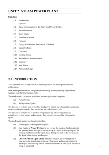
UNIT 2 STEAM POWER PLANTSteam Power PlantStructure2.1IntroductionObjectives2.2Basic Consideration in the Analysis of Power Cycles2.3Steam Generator2.4Super Heater2.5Feed Water Heater2.6Furnaces2.7Energy Performance Assessment of Boilers2.8Steam Turbines2.9Condenser2.10 Cooling Tower2.11 Steam Power Station Control2.12 Summary2.13 Key Words2.14 Answers to SAQs2.1 INTRODUCTIONTwo important area of application of thermodynamics are power generation andrefrigeration.Both power generation and refrigeration are usually accomplished by a system thatoperates on a thermodynamics cycle.Thermodynamics cycles can be divided into two generation categories :(a)Power Cycles(b)Refrigeration CyclesThe devices or systems used to produce a net power output are often called engines andthe thermodynamics cycles they operate on are called power cycle.The devices or systems use to produce refrigeration are called refrigerator, airconditioners or heat pumps and the cycles they operates on are called refrigerationcycles.Thermodynamic cycles can be categorized as :(a)Power cycles or Refrigeration cycles.(b)Gas Cycles or Vapor Cycles : In gas cycles, the working fluid remains inthe gaseous phase throughout the entire cycle, where as in vapor cycles theworking fluid exists in the vapor phase during one part of the cycle and inthe liquid phase during another part.(c)Closed Cycles or Open Cycles : In closed cycles, the working fluid isreturned to the initial state at the end of the cycle and is re-circulated. Inopen cycle, the working fluid is renewed at the end of each cycle instead ofbeing re-circulated.21
Power Plant EngineeringObjectivesAfter studying this unit, you should be able to know steam generator, steam turbine, and describe cooling towers and condensers.2.2 BASIC CONSIDERATION IN THE ANALYSIS OFPOWER CYCLESActual CycleThe cycles encountered in actual devices are difficult to analyze because of thepresence of complicating effects, such as friction and the absence of sufficienttime for establishment of the equilibrium conditions during the cycle.Ideal CycleWhen the actual cycle is stripped of all the internal irreversibilities andcomplexities, we end up with a cycle that resembles the actual cycle closely but ismade up totally of internally reversible processes. Such a cycle is called an Idealcycle.Heat EnginesHeat engines are designed for the purpose of converting other form ofenergy to work and their performance is expressed as thermal efficiency. th WnetQinThe Idealization and Simplification(a)The cycle does not involve any friction.(b)All expansion and compression process take place in a quasiequilibrium manner.(c)The pipe connecting the various component of a system are wellinsulated and heat transfer and pressure drop through them arenegligible.Carnot CycleThe Carnot cycle is composed of 4 totally reversible processes :(a)Isothermal heat addition at high temperature (TH).(b)Isentropic expansion from high temperature to low temperature.(c)Isothermal heat rejection at low temperature (TL).(d)Isentropic compression from low temperature to high temperature.Thermal efficiency of Carnot cycle th, carnot 1 TLTHThe Carnot Vapor Cycle(a)22A steady-flow Carnot cycle executed with the saturation dome of a puresubstance is shown in Figures 2.1(a) and (b). The fluid is heated reversiblyand isothermally in a boiler (process 1-2), expanded isentropically in aturbine (process 2-3), condensed reversibly and isothermally in a condenser(process 3-4) and compressed isentropically by a compressor to the initialstate (process 4-1).
(b)The Carnot cycle is not a suitable model for vapor power cycle because itcannot be approximated in practice.Steam Power PlantT2143s(a)T2143s(b)Figure 2.1 : Carnot CycleRankine Cycle : The Ideal Cycle for Vapor Power Cycle(a)The impracticalities associated with Carnot cycle can be eliminated bysuperheating the steam in the boiler and condensing it completely in thecondenser. This cycle that results is the Rankine cycle, which is the idealcycle for vapor power plants. The construct of power plant and T-s diagramis shown in Figures 2.2(a) and (b).qinBoiler3W turb,out2Turbinewpump,inPump14 qoutCondenser(a)T3qinW turb,out214’qoutwpunp,ins(b)Figure 2.2 : Rankine Cycle23
Power Plant Engineering(b)The ideal Rankine cycle dose not involve any internal irreversibilities(c)The Rankine cycle consists of the following four processes :1-2 : Isentropic compression in pump (compressors)2-3 : Constant pressure heat addition in boiler3-4 : Isentropic expansion in turbine4-1 : Constant pressure heat rejection in a condenserProcess 1-2Water enters the pump at state 1 as saturated liquid and is compressedisentropically to the operating pressure of the boiler. The water temperatureincreases somewhat during this isentropic compression process due to slightdecrease in the specific volume of the water. The vertical distance betweenstate 1 and 2 on the T-s diagram is greatly exaggerated for clarity.Process 2-3Water enters the boiler as a compressed liquid at state 2 and leaves as asuperheated vapor at state 3. The boiler is basically a large heat exchangerwhere the heat originating from combustion gases, is transferred to thewater essentially at constant pressure. The boiler together with the sectionwhere the steam is superheated (the superheater), is often called the steamgenerator.Process 3-4The superheated vapor at state 3 enters the turbine, where it expandsisentropically and produces work by rotating the shaft connected to anelectric generator. The pressure and the temperature of the steam dropsduring this process to the values at state 4, where steam enters thecondenserProcess 4-1At this state, the steam is usually a saturated liquid-vapor mixture with ahigh quality. Steam is condensed at constant pressure in the condenserwhich is basically a large heat exchanger, by rejecting heat to a coolingmedium from a lake, or a river. Steam leaves the condenser as saturatedliquid and enters the pump, completing the cycle.Energy Analysis of the Ideal Rankine CycleAll four components associated with the Rankine cycle (the pump, boiler, turbineand condenser) are steady-flow devices, and thus all four processes that make upthe Rankine cycle can be analyzed as steady-flow process.The steady flow equation per unit mass of steam reduces to(qin qout ) (win wout ) he hi (kJ/kg)Pump (q 0) :wpump, in (h2 h1 ) v ( P2 P1 )where h1 h f @ p1 and v v1 v f @ p1Boiler (w 0) :qin h3 h2Turbine (q 0) :24wturbine, out (h3 h4 )
Steam Power PlantCondenser (w 0)qout h4 h1The thermal efficiency of the Rankine cycle is determine from th wherewnetq 1 outqinqinwnet qin qout wturbine, out wpump, inDeviation of Actual Vapor Power Cycle from Idealized OnesThe actual vapor power cycle differs from the ideal Rankine cycle, as a result ofirreversibilites in various components. Fluid friction and heat loss to thesurroundings are the two common sources of irreversibilites.Fluid friction causes pressure drop in the boiler, the condenser and the pipingbetween various components. Also the pressure at the turbine inlet is somewhatlower than that at the boiler exit due to the pressure drop in the connecting pipes.To compensate for these pressure drops, the water must be pumped to asufficiently higher pressure than the ideal cycle. This requires a large pump andlarger work input to the pump, are shown in Figures 2.3(a) and (b).TIDEAL CYCLEPressure drop inthe boilerPressure dropin the pump3Irreversibility inthe turbine2ACTUAL CYCLE41Pressure drop inthe condensers(a)T32a2s14s4a(b)sFigure 2.3 : Vapour Power CycleThe other major source of irreversibility is the heat loss from the steam to thesurrounding as the steam flows through various components.Particular importance is the irreversibilites occurring within the pump and theturbine. A pump requires a greater work input, and a turbine produces a smaller25
Power Plant Engineeringwork output as a result of irreversibilties. Under the ideal condition the flowthrough these devices is isentropic.The deviation of actual pumps and turbine from the isentropic ones can beaccurately accounted by isentropic efficiencies, define as : p ws h2 s h1 wa h2a h1 T wa h3 h4a ws h3 h4 sHow can We Increase the Efficiency of the Rankine cycle?Than Rankine cycle efficiency can be increased by increasing average temperatureat which heat is transferred to the working fluid in the boiler or decreasing theaverage temperature at which heat is rejected from the working fluid in thecondenser. That is, the average fluid temperature should be as high as possibleduring heat addition and as low as possible during heat rejection.The three ways by which efficiency of the Rankine cycle can be increased are :(a)Lowering the condenser pressure (Lowers Tlow, av).(b)Superheating the steam to high temperatures (Increases Thigh, av).(c)Increasing the boiler pressure (Increases Thigh, av).Lowering the Condenser Pressure (Lowers Tlow, av)Steam exists as a saturated mixture in the condenser at the saturationtemperature corresponding to the pressure inside the condenser. Therefore,lowering the operating pressure of the condenser automatically lower thetemperature of the steam, and thus the temperature at which heat is rejected.The effect of lowering the condenser pressure on the Rankine cycleefficiency is illustrated in below Figure 2.4.T322’411’Increase in wnet4’P’4 P4sFigure 2.4 : Rankine CycleDrawback of lowering the condenser pressure is increase in the moisturecontent of the steam at the final stages of the turbine. The presence of largequantities of moisture is highly undesirable in turbines because it decreasesthe turbine efficiency and erodes the turbine blades.Superheating the Steam to High Temperatures (Increases Thigh, av)26The average temperature at which heat is added to the steam can beincreased without increasing the boiler pressure by superheating the steamto high temperatures. The effect of superheating on the performance ofvapor power cycle is illustrated on a T-s diagram as shown in Figure 2.5.
Superheating the steam to higher temperatures has very desirable effect : Itdecreases the moisture content of the steam at the turbine exit as can beseen in T-s diagram as shown in Figure 2.6.Steam Power PlantThe temperature to which steam can be superheated is limited bymetallurgical consideration.TIncrease in wnet3’3214’4Figure 2.5 : Vapour Power CycleTIncreasein w net3’3Increasein wnet2’214’4sFigure 2.6 : Vapour Power CycleIncreasing the Boiler Pressure (Increases Thigh, av)The average temperature during the heat addition process is to increase theoperating pressure of the boiler, which automatically raises the temperatureat which boiling take place. This, in turn, raises the average temperature atwhich heat is added to the steam and thus raises the thermal efficiency ofthe cycle.The Ideal Reheat Rankine CycleThe efficiency of the Rankine cycle can increase by expanding the steam in theturbine in two stages, and reheating it in between. Reheating is a practical solutionto the excessive moisture problem in turbines, and it is commonly used in modernsteam power plants.The schematic and T-s diagram of the ideal reheat Rankine cycle is shown inFigures 2.7(a) and (b).The ideal reheat Rankine cycle differs from the simple ideal Rankine cycle in thatthe expansion process take place in two stages. In first stage (the high-pressureturbine), steam is expanded isentropically to an intermediate pressure and sentback to the boiler where it is reheated at constant pressure, usually to the inlettemperature of the first turbine stage. Steam then expands isentropically in thesecond stage (low-pressure turbine) to the condenser pressure.27
3Power Plant EngineeringHigh - pturbineBoilerLow ptrineReheater 4P 4 P5 turbine42’Low pressure4261s(b)Figure 2.7 : Ideal Reheat Rankine CycleThus the total heat input and the total work output for a reheat cycle become :qin qprimary qreheat (h3 h2 ) (h5 h4 )wturbine, out wturbine, I wturbine, II (h3 h4 ) (h5 h6 )The Ideal Regenerative Rankine CycleAs shown in Figure 2.8, T-s diagram for the Rankine cycle shows that heattransferred to the working fluid during process 2-2 at a relatively lowtemperature. This lowers the average heat-addition temperature and thus the cycleefficiency.To remedy this shortcoming, the temperature of the liquid leaving the pump(called feedwater) before it enters the boiler need to be increased.TLowtemperatureheat additionSteam exitingboiler2’Steamentering boiler214s28Figure 2.8 : Ideal Regenerative Rankine Cycle
Another way of increasing the thermal efficiency of the Rankine cycle is byregeneration. During a regeneration process, liquid water (feedwater) leaving thepump is heated by steam bled off the turbine at some intermediate pressure indevices called feedwater heaters.Steam Power PlantThere are two type of feedwater Heaters :(a)Open Feedwater Heater(b)Closed Feedwater HeaterOpen Feedwater HeaterAn open (or direct-contact) feedwater heater is basically a mixing chamber,where the steam extracted from the turbine mixes with the feedwater exitingthe pump. Ideally, the mixture leaves the heater as a saturated liquid at theheater pressure. The schematic of a steam power plant with one openfeedwater heater and the T-s diagram of the cycle are shown in theFigure 2.9.The heat and work interaction of a regenerative Rankine cycle with onefeedwater heater can be expressed per unit mass of steam flowing throughthe boiler as follows :qin h5 h4qout (1 y) (h7 h1 )wturbine, out (h5 h6 ) (1 y) (h6 h7 )wturbine, in (1 y) wpump I, in wpump II, iny wherem6m5wpump I, in v1 ( p2 p1 )wpump II, in v3 ( p4 p3 )5TurbineBoileryOpenFWH6-y 1-y42CondenserPump IIPump 1(a)T5463317s(b)Figure 2.9 : Steam Power Plant29
Power Plant EngineeringThe thermal
UNIT 2 STEAM POWER PLANT Steam Power Plant Structure 2.1 Introduction Objectives 2.2 Basic Consideration in the Analysis of Power Cycles 2.3 Steam Generator 2.4 Super Heater 2.5 Feed Water Heater 2.6 Furnaces 2.7 Energy Performance Assessment of Boilers 2.8 Steam Turbines 2.9 Condenser 2.10 Cooling Tower 2.11 Steam Power Station Control 2.12 Summary 2.13 Key Words 2.14 Answers
