Transcription
Why ScreeningScreened Cabling vs UnscreenedWhite PaperNexans Cabling SolutionsMay 2013
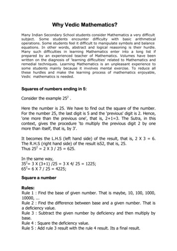
Screened vs UnscreenedIn addition to the performance classes and categories within structured copper cabling thereare two main different technologies: shielded and unshielded twisted pair (U/UTP) systems.Both types have been in existence since the earliest cabling standards were defined. Whileshielded cabling became popular from the outset in countries like Germany, Austria,Switzerland and France, U/UTP was quickly adopted in the rest of the world. Although bothsystems work fine at 1 Gigabit Ethernet data rates, shielded systems can demonstrate superiorperformance at higher data rates such as 10G due to their ability to reliably support higherfrequency transmission.Different cable constructions
What is a cable shield good for?F/UTPA F/UTP cable has a common shield (foil) around the four pairs of the data cable. Thiscommon shield minimises:1. Radiation of data transmission signals which leave the cable and disturb neighboringcables (e.g. adjacent cables in the same bundle)2. Unwanted high frequency signals from other cables or other sources of noise fromentering the cable.Both effects are very important to maintain a high quality of data transmission. If an aliensignal is strong enough it could overlap the wanted signal and could slow down the systemperformance or even bring down the network.S/FTPIn addition to a common shield, a S/FTP cable has individual foils wrapped around each ofthe 4 twisted pairs. The foil protects the four different signals from each other – which leads tomuch higher NEXT (Near End Crosstalk) values. Increased NEXT means higher signal to noiseratios, improved transmission performance and faster system throughput. The NEXT valuesprovided by S/FTP cables cannot be achieved with other cable designs like U/UTP. Thereforeonly S/FTP for Cat.7 (600 MHz) and Cat.7A (1000 MHz) is specified in ISO 11801 but noU/UTP.10GBASE-T – the beginning of a new cable problem: Alien CrosstalkThe standard for 10 Gigabit Ethernet over twisted-pair copper (10GBASE-T) was published in2006 providing a new protocol which represented a ten-fold increase in comparison with theprevious 1000Base-T version.1000BASE-T transmission requires all internal cabling parameters (Attenuation, NEXT, ReturnLoss etc) to be specified for the range 1 to100MHz, this can be achieved using a Cat.5e(Class D) cabling system.10GBASE-T however requires a cabling channel with all parameters specified to an upperfrequency of 500MHz which can be achieved using a Cat.6A (Class EA or higher) system.During the development of 10GBASE-T it became clear that sensitivity to external noise was aproblem. This led to the specification of external noise parameters to assess the effect of noisefrom cables within a bundle on another cable in the same bundle. This effect is known as AlienCrosstalk which worsens as frequency increases.
10GBASE-T systems faced with excessive external noise do not “auto-negotiate” down to alower data rate – they simply shut down.Good Alien Crosstalk performance is therefore essential for cabling systems designed to support10GBASE-T. 10GBASE-T is – due to high transmission frequency and complex encoding – quitesensitive to external noise Shielded systems have a higher coupling attenuation which gives them in-built protectionagainst external noise (Alien Crosstalk). U/UTP systems generally have 0dB margin against the external noise parameters Shielded systems support 10G simply by design.10GBase-T installation: U/UTP vs. FTPUnshielded systems Increased separation distance frompower cablingMix of applications (1 Gb/s and 10Gb/s) in one conduit may lead toANEXT disturbanceShielded systems Reduced separation distance frompower cablingMix of applications (1 Gb/s and 10Gb/s) possible in one conduitNo ANEXT field testing“U/UTP is easier and cheaper to install” . –– is there any truth behindthis myth?In reality no, both from a design and installation perspective, the benefits of installing ashielded system outweigh the perceived ease and lower cost of installing a U/UTP system.Separation distance from data- to power cableIn the standard EN50174-2 coupling attenuation (ca) limits are defined for different cabletypes. They are classified from A (low ca, poor) to D (highest ca, very good).Table 3 from EN50174-2
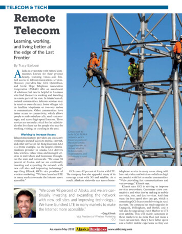
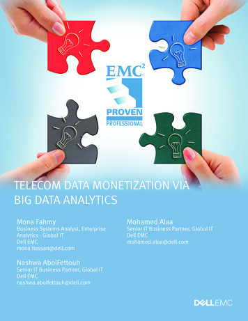
Installers need to know the segregation class to find out the required distance between dataand power cables. The higher the coupling attenuation of the data cable is – the shorter is thedistance allowed. Below you will find 3 examples of what that could mean in practice(screenshots are taken from Nexans Toolkit – available for free download on Nexans website):Example 1: U/UTP: (Class B cable – coupling attenuation / 40dB) - 225mm
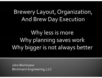
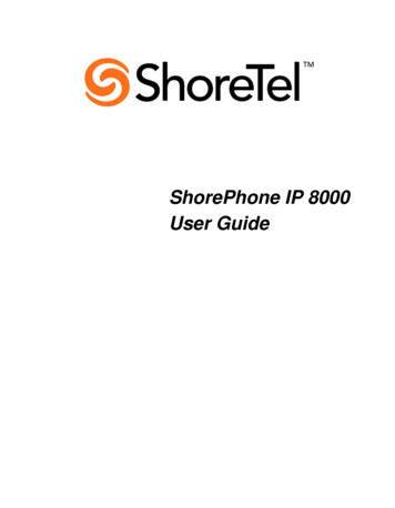
Example 2: F/UTP (Class C - coupling attenuation / 55dB) - 114 mm
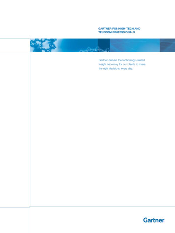
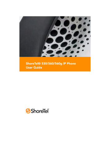
Example 3: S/FTP (Class D - coupling attenuation / 80dB) - 24mmU/UTP cable needs more distance from power cable than any shielded cable. In practice morespace means more costs because bigger cable ducts/trays or additional trays dedicated topower or data cables are needed. Worse, these additional requirements are often overlookedor ignored which can generate areas of high disturbance at critical points in the network.These calculations realised according to the rules described in the EN50173 cabling standardreally highlight the effectiveness of the cable screen.Alien Crosstalk (AXT) theory and comparative measurements (unscreened versus screened)confirm that screened cables also provide a high level of protection against EMI at highfrequencies.
EarthingProtective earthing requirement applies to unshielded, shielded and fibre optic cabling systemsalike. All metal parts regardless of the type of cabling must be bonded for personnel safetyreasons.The functional earthing requirement applies to shielded system only. But the only additionaloperation to be performed is to connect the screen of the connector to the screen of the cableduring the termination process on site.Bonding of the connector screen with the patch panel and of the patch panel with the cabinetare automatically performed when using Nexans Cabling Systems.SummaryScreened cabling brings valuable EMC performance improvement against unscreened systems:Shielding effectiveness is of particular importance where 10G Ethernet is concerned. Screenedor shielded cabling is immune to alien crosstalk transmitted from adjacent cables with the resultthat the installed system is able to meet the A-XT requirement by design.Screened cabling, when grounded at both ends, is a minimum 40dB better i.e. less susceptibleto picking up RFI from external sources than unshielded cabling.
What do suppliers of test equipment say?Ideal Industries“ With modern cables, AXT is negligible for data rates up to 1GB/s, but under certaincircumstances, it can be a problem for rates of 10GB/s or higher. Whenever cabling has tomeet ISO 11801 Class EA or Cat.6A field testing requirements, it must be compliant with AXTspecifications. This can be proven indirectly, by measuring the coupling attenuation. Basically,this attenuation describes cabling’s immunity against EMI (Electromagnetic Interference)samples in the laboratory. The manufacturer only needs to prove a certain product’s couplingattenuation performance once; this doesn’t have to be repeated for every customer project.Once laboratory tests have been passed, the manufacturer can issue a certificate for AXTcompliance and doesn’t have to perform AXT field measurements. This is the safest, easiestand fastest option for installers.If a manufacturer can’t supply a certificate, AXT has to be measured in the field by the installer.The applicable field test standard is Class EA, according to ISO 11801. Due to the theoreticalamount of testing necessary to certify a complete installation, standards only call for sampletesting. The installer has to choose a number of short, medium and long cables as so called‘disturbed’ cables. After selecting the ‘disturbed’ cables, the user has to select for every‘disturbed’ cable a number of ‘disturbers’, means cables that potentially can interfere with the‘disturbed’ cable. The biggest difficulty in AXT testing is sample selection. Since only a fewpercent of the complete installation will be tested, the selection of samples is very subjective.Therefore, AXT tests may produce different results depending on the samples selected.” and beyond 10G?40GBaseT is currently in discussion in IEEE, ISO and TIA. So nothing is really defined yet butone thing’s for sure 40G will be much more difficult for the cabling system than 10G.Weighing up the different parameters
The complexity of coding is related to bandwidth - higher frequencies would allow lesscomplex coding which could reduce the chip costs. But higher frequencies would mean higherattenuation. Attenuation on the other hand is related to reach (length). The higher the cableattenuation is, the shorter the link length would need to be to offset this, and/or the higher thepower for the signal has to be. This means that length is directly linked with energy costs. Asthe majority of data centers are well below 100m, new standards for 40G cabling will be at areduced maximum reach. Much research is underway to examine these relationships betweenreach and performance but it is inevitable shielded cable will be the system of choice.ConclusionShielded cabling does offer a couple of benefits compared to U/UTP. The cable shield offersnot only some additional mechanical stability but also a reliable protection against unwantedsignals (EMC). Without doubt a shield is the best way to avoid Alien Crosstalk problems in10G networks. And even beyond 10G shielded Cat.7A solutions seem to be the best choice forhigher speed applications.
Nexans Cabling Solutions. All rights reserved. LANmark, LANsense and GG45 are registered trademarks of Nexans. Release date: May 2013.Nexans Cabling SolutionsAlsembergsesteenweg 2, b3 - B-1501 BuizingenTel: 32 (0)2 363 38 00 - Fax: 32 (0)2 365 09 99Nexans Cabling Solutions UK and Intelligent Enterprise Solutions Competence Centre2 Faraday Office Park - Faraday Road - Basingstoke - Hampshire RG24 8QQTel: 44 (0)1256 486640 - Fax: 44 (0)1256 486650www.nexans.com/LANsystems - info.ncs@nexans.com
Separation distance from data - to power cable : In the standard EN50174-2 coupling attenuation (ca) limits are defined for different cable types. They are classified from A (low ca, poor) to D (highest ca, very good). Table 3 from EN50174-2 : Installers need to know the segregation class to find out the distance between datarequired - and power cables. The higher the coupling attenuation of .