Transcription
INSTALLING LHD CABLELinear heat detection cableApplication LHD cable 2011 DURAN ELECTRONICA S.L. - All rights reserved · www.duranelectronica.comI-manApplicationLHD-V01
INDEXpage1.TEMPERATURE RANGES. . . . . . . . . . . . . . . . . . . . . . . . . . . . . . . . . . . . . . . . . . . . . . . . . . . . . . 52.INSTALLING LHD CABLE. . . . . . . . . . . . . . . . . . . . . . . . . . . . . . . . . . . . . . . . . . . . . . . . . . . . . . 52.1 Splicing. . . . . . . . . . . . . . . . . . . . . . . . . . . . . . . . . . . . . . . . . . . . . . . . . . . . . . . . . . . . . . . 62.2 Splicing Connectors. . . . . . . . . . . . . . . . . . . . . . . . . . . . . . . . . . . . . . . . . . . . . . . . . . . . . . 63.AUTOMOBILE TUNNEL DETECTION. . . . . . . . . . . . . . . . . . . . . . . . . . . . . . . . . . . . . . . . . . . . . . 74.REFRIGERATED AND COLD STORAGE DETECTION. . . . . . . . . . . . . . . . . . . . . . . . . . . . . . . . . . . 74.1 Refrigerated Storage Areas . . . . . . . . . . . . . . . . . . . . . . . . . . . . . . . . . . . . . . . . . . . . . . . . 74.2 Open Rack Storage without Sprinklers. . . . . . . . . . . . . . . . . . . . . . . . . . . . . . . . . . . . . . . . 74.3 Open Rack Storage with Sprinkler Protection. . . . . . . . . . . . . . . . . . . . . . . . . . . . . . . . . . . 84.4 Pre-Action and Deluge Sprinkler Systems. . . . . . . . . . . . . . . . . . . . . . . . . . . . . . . . . . . . . . 94.5 Zone Definitions . . . . . . . . . . . . . . . . . . . . . . . . . . . . . . . . . . . . . . . . . . . . . . . . . . . . . . . . 95.BAGHOUSE AND DUST COLLECTOR DETECTION. . . . . . . . . . . . . . . . . . . . . . . . . . . . . . . . . . . . 96.PROXIMITY DETECTION. . . . . . . . . . . . . . . . . . . . . . . . . . . . . . . . . . . . . . . . . . . . . . . . . . . . . . 106.1 Proximity Detection. . . . . . . . . . . . . . . . . . . . . . . . . . . . . . . . . . . . . . . . . . . . . . . . . . . . . . 106.2 Motors, Generators, Pumps & Valves . . . . . . . . . . . . . . . . . . . . . . . . . . . . . . . . . . . . . . . . . 106.3 In Cabinet Detection. . . . . . . . . . . . . . . . . . . . . . . . . . . . . . . . . . . . . . . . . . . . . . . . . . . . . 107.CABLE TRAY DETECTION . . . . . . . . . . . . . . . . . . . . . . . . . . . . . . . . . . . . . . . . . . . . . . . . . . . . . 117.1 Cable Trays . . . . . . . . . . . . . . . . . . . . . . . . . . . . . . . . . . . . . . . . . . . . . . . . . . . . . . . . . . . . 117.2 Estimating LHD cable Length for Cable Trays. . . . . . . . . . . . . . . . . . . . . . . . . . . . . . . . . . . 118.RACK STORAGE DETECTION. . . . . . . . . . . . . . . . . . . . . . . . . . . . . . . . . . . . . . . . . . . . . . . . . . . 128.1 Rack Storage. . . . . . . . . . . . . . . . . . . . . . . . . . . . . . . . . . . . . . . . . . . . . . . . . . . . . . . . . . . 128.2 Open Rack Storage without Sprinklers. . . . . . . . . . . . . . . . . . . . . . . . . . . . . . . . . . . . . . . . 128.3 Open Rack Storage with Sprinkler Protection. . . . . . . . . . . . . . . . . . . . . . . . . . . . . . . . . . . 128.4 Pre-Action and Deluge Sprinkler Systems. . . . . . . . . . . . . . . . . . . . . . . . . . . . . . . . . . . . . . 129.CONVEYOR DETECTION . . . . . . . . . . . . . . . . . . . . . . . . . . . . . . . . . . . . . . . . . . . . . . . . . . . . . . 13I-manApplicationLHD-V013
4 2011 DURAN ELECTRONICA S.L.All rights reserved · www.duranelectronica.com
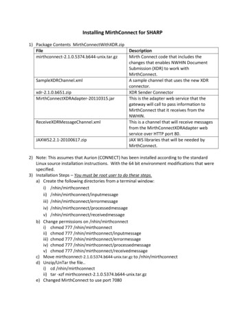
1. TEMPERATURE RANGES LHD Cable is approved as a heat actuated device for use on a supervised fire alarm control/releasing panel. LHDCable is available in multiple temperatures, and ratings are the same as those for heat detectors and sprinklers. Refer to ourtemperature rating chart (Figure 1) for assistance in choosing the best wire for your environment. LHD Cable can be installedfor both area protection and local applications (close to the hazard or potential heat source) for a faster response. LHD Cable use is intended to be in conjunction with an approved fire alarm control/releasing panel and installed incontinuous runs without T-Taps or branch lines.LHD Cable should always be enclosed in conduit for the following; when installed 1.83 meters or less from the floor, all runsthrough the floor, or entry into a manual pull station.Maximum AmbientInstall TemperatureAlarm TemperatureUp to 40ºCUp to 50ºC68ºC78ºCUp to 70ºCUp to70ºC88ºC104ºCFig. 12. INSTALLING LDH CABLEDuring installation, it is important to handle LHD Cable with a degree of care. The polymer outer covering is very durable, butthe inner core wires and thermal reactive sheathing can be damaged if not handled properly. The following are some installationguidelines and hints to assist you in avoiding damage to the LHD Cable, and to help ensure a successful and trouble freeinstallation. ALWAYS test wire before installation with a multimeter to be sure there are no shorts in the wire. LHD Cable integrityis also tested prior to shipping for quality assurance. ALWAYS allow the proper amount of sag when installing the detection wire. Please refer to the sag chart below (Figure2) for detailed information.Sag .54cm2.85cmWire Mount Spacing1.5m1.5m1.5m1.5mFig 2 ALWAYS be sure to install LHD Cable to meet local and national codes, and installation guidelines. NEVER tighten mounting clips to the point where the detection wire is pinched, stretched, or to the point where itcannot move freely within the mounting device. NEVER bend the detection wire to a 90º angle. All bends or turns should be rounded with a minimum 7.6 cm radius asshown below in figure 3.I-manApplicationLHD-V015
NEVER paint the detection wire, per UL and FM requirements. NEVER use wire nuts or similar devices as all connections should be made with approved splicing techniques usingterminals blocks. NEVER stretch the detection wire, always allow some slack in the runs especially in refrigerated storage applications. NEVER place the detection wire where it can be damaged by foot, equipment, or truck traffic. NEVER store detection wire in areas where the ambient temperature is near, or exceeds the activation temperature ofthe wire. NEVER install LHD Cable using non-approved fasteners, this may damage the wire, cause false alarms, and void thewarranty.2.1 SplicingWhen splicing LHD Cable, be sure to securely fasten the detection wires in the Splicing Block to prevent accidental dislodgingof the wires. Thoroughly wrap the splice by overlapping the layers approximately half the width of the splicing tape. Thiswill prevent humidity or dust to enter the splicing connection. If splicing in low temperatures (below 0 C, be sure to use LowTemperature Splicing Tape. If connections need to be weatherproof, Sealant Tape should be used.2.2 Splicing ConnectorsWhen splicing LHD Cable, it is necessary to use a splicing block to ensure a durable and proper connection. Splicing tape is alsoused to wrap the point of the splice to prevent moisture and contamination build up.6 2011 DURAN ELECTRONICA S.L.All rights reserved · www.duranelectronica.com
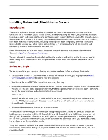
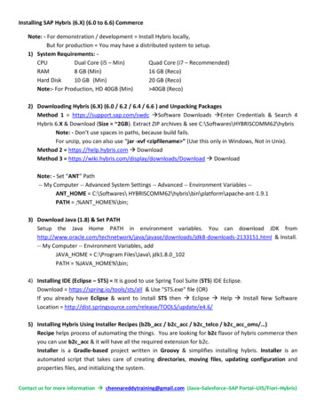
3. AUTOMOBILE TUNNEL DETECTIONWhen creating a LHD Cable design for tunnels, keep in mind that a single zone of LHD Cable can extend up to 3.000 meters. Asseen in the diagram below, in most cases, the detection wire is installed on the ceilings over the traffic areas. A complete designwould include coverage of not just the traffic areas but also equipment and mechanical rooms, tray runs and tunnel ventilatingsystems.Figure 5 illustrates a simple tunnel application. With a maximum of 3.000 meters4. REFRIGERATED AND COLD STORAGE DETECTION4.1 Refrigerated Storage AreasWhen using LHD Cable as an initiating device for pre-action sprinkler systems in refrigerated storage areas, attention should bepaid to the guidelines provided by local regulations. Generally, local regulations require linear heat detection wire be installedat spacing not greater than that allowed for a ceiling sprinkler system. For this reason, when ceiling detection is required in arefrigerated storage application, the ceiling detection wire may be fastened to the sprinkler piping.When installing LHD Cable in conjunction with a sprinkler system in a rack system, local regulations must be followed along withmanufacturer’s recommendations. In the case of signal or double row racks, one line of LHD Cable is needed for each sprinklerlevel. The detection wire should be attached to the load beam at the sprinkler level and run in the transverse or longitudinal fluespace. For multiple row racks, each sprinkler line would require a corresponding run of detection wire.The following sections detail using LHD Cable in a variety of rack storage systems including open rack with and without sprinklerprotection and refrigerated storage. When installing LHD Cable in a rack system with or without a sprinkler system, localregulations must be followed along with the manufactures recommendations.4.2 Open Rack Storage without SprinklersWhen installing the LHD Cable in open rack system without a sprinkler system, the number of detection wire runs is based onthe height of the rack. As a general rule, there should be one detection wire run for every 3 meters of rack height. The detectionwire should be attached to the load beam and run in the transverse flue space. For example, an 5.5 meter rack should be given two wire runs while a 12 meter system should have four wire runs. For example, an 5.5 meter rack should be given two wire runs while a 12 meter system should have four wire runs.I-manApplicationLHD-V017
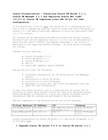
4.3 Open Rack Storage With Sprinkler protectionIn the case of signal or double row racks, one line of LHD Cable is needed for each sprinkler level as shown in figure 7. Thedetection wire should be attached to the load beam at the sprinkler level and run in the transverse flue space. For multiple rowracks, each sprinkler line would require a corresponding run of detection wire.Installation: The leader wire is run from the fire alarm control/releasing panel to a J-Box mounted to the rack for a particularzone. The LHD Cable is then run from the J-Box through the racks as indicated in Figures 6 and 7, which may then cross the isleto a second rack system. When mounting the detection wire on the horizontal load beam, utilize the angle iron or open channelsof the rack structure to help protect the detection wire from accidental breakage from forklifts and product. The wire may befastened to these structures by using cable clips made from nylon 6.6 to withstand the continuous cold or subzero temperatures.When crossing aisles, be sure to elevate the LHD Cable enough to stay clear of any possible damage that may be caused byforklifts, cranes or product. Detection wire may be run one section above the sprinkler level to prevent damage to both thesprinkler pipe and detection cable simultaneously which may alarm and begin to flow water.A refrigerated storage warehouse may require a Class A detection circuit rather than Class B. For this type of installation, acopper wire is run from a J-Box at the end of the detection wire zone back to the panel to complete the circuit.LHD Cable will contract as temperature drops when a refrigerated storage warehouse is brought down to operating temperature.Installations in refrigerated storage areas, prior to cool down, require a certain amount of sag to be maintained during installationto accommodate for contraction. Figure 8 is a chart to assist in determining the amount of sag, which should be maintainedbetween mounting fasteners.Sag ChartTemperature-7º-17º-29º-40ºFig. 88 2011 DURAN ELECTRONICA S.L.All rights reserved · Wire Mount Spacing1.5m1.5m1.5m1.5m
4.4 Pre-Action and Deluge Sprinkler SystemsWhen using LHD Cable as an initiating device for pre-action sprinkler systems, attention should be paid to the spacing andlocation guidelines provided when applicable by local regulations.4.5 Zone DefinitionsIt is important to note that a detection zone allocation for LHD Cable should not be confused with a zone allocation for asprinkler system. If a sprinkler zone extends beyond the capabilities of a signal detection zone then an additional detection zonemust be added. In this case, either detection zone will operate the same solenoid valve for the sprinkler zone. Detection zonecoverage should not extend beyond the coverage of the sprinkler zone.5. BAGHOUSE AND DUST COLLECTOR DETECTIONThe shape and design of baghouses and dust collectors vary. The outer perimeter of the unit must be protected as illustratedin Figure 9. Depending on the design of the unit, LHD Cable may be run on an inner perimeter as well as seen in Figure 10. Ifrequired, detection cable may also be run in conduit to a higher level inside the unit.Either guide wire or L-Brackets may be used to secure the detection wire approximately 10,9 meters above the base of the unit.When using L-Brackets, be sure to support the detection cable a maximum of every 1.5 meters.I-manApplicationLHD-V019
6. PROXIMITY DETECTION6.1 Proximity DetectionFor proximity or special application protection, LHD cable should be installed on or immediately above the hazard in a way thatallows for it to be exposed to a rise in temperature caused by a fire condition.6.2 Motors, Generators, Pumps, ValvesLHD cable can be mounted directly on the surface of virtually any type of mechanical and electrical equipment. This type ofinstallation allows for quick response to overheating equipment, which can provide warning earlier than using area detectionalone. Typically, the LHD cable used to protect equipment directly is of a higher activation temperature. The higher temperaturedetection wire can be spliced into the same detection wire used for the area detection and both be considered part of the samezone. The distance locating option may be used to identify the higher tem
Installation: The leader wire is run from the fire alarm control/releasing panel to a J-Box mounted to the rack for a particular zone. The LHD Cable is then run from the J-Box through the racks as indicated in Figures 6 and 7, which may then cross the isle to a second rack system. When mounting the detection wire on the horizontal load beam, utilize the angle iron or open channelsFile Size: 615KBPage Count: 16