Transcription
International Journal of Electrical Engineering.ISSN 0974-2158 Volume 10, Number 1 (2017), pp. 47-56 International Research Publication Househttp://www.irphouse.comRailway Traction System: Current Status andApportunitiesShweta E. KalePG StudentG.H. Raisoni College Of EngineeringDepartment of electrical Engineering,India.K. D. JoshiAssociate professorG.H. Raisoni College Of EngineeringDepartment of electrical Engineering,India.AbstractIn India most common means of transportation is railway. Most of the railwayline is electrified, which increases the demand for electricity. Indian Rail usesonly two phases from three-phase electric power supply to fed locomotive.Arrivals of locomotive at substation are dynamic load. Due to this voltage dropoccur at OHE and three phase supply line also, result of this is inefficientoperation of motor in loco. Due to excessive load the circuit breakers may tripwithout any fault on line. To avoid this problem many research is going on,some are given in this paper.The paper shows the present scenario and advancement of Indian railwayIndex Terms: traction substation, OHE , locoI. INTRODUCTIONRailway is a largest means of transportation in India and it is ranked in the world asfourth largest railway network. Railway works under the Indian railway which is astate-owned organization of the Ministry of railway.Indian railway traction system uses 1.5 kV DC around Bombay and 25Kv ac is used inrest of the country. The supply for traction system is taken from state utility which isthree phase source at 132/220 kV. The traction OHE required 25 kV supply, so onlytwo phases are taken and step down to single phase 25 kV through transformer which
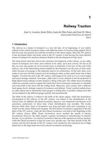
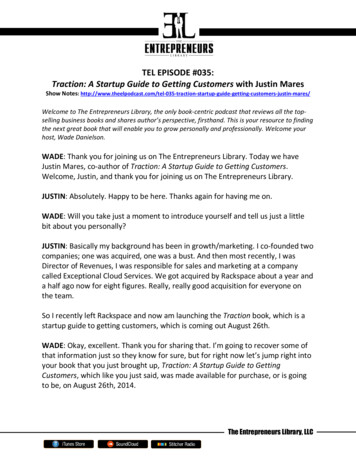
48Shweta E. Kale and K. D. Joshiis present at traction substation. This 25kV is fed to the OHE from feeder then to locovia pantograph which is at the roof of loco. When there are several loco at substationoperating at a time then there is voltage drop at OHE. Because of this, inefficientoperation of motor takes place as large amount of current is drawn from line.II. HISTORY OF RAILWAY TRACTION IN INDIAIn 1853 railways were started in India from Mumbai to Thane. Starting with steamlocomotive, railway up gradation is continuously going with advancement oftechnology. The first commercial train journey on 16 April 1853 in India betweenBombay and Thane with 14 carriage long train drawn by 3 locomotives named Sultan,Sindh and Sahib. It was around 21 miles in length and took approximately 45 minutes.The electrification of railway in Indian is started in 1925 as it is free from pollution,fast response than earlier loco, energy efficient regenerative breaking system. Indianrailway adopted 25 kv 50 Hz AC traction which was based on French railwaytechnology in 1957 and the first train run was on 1959. In 80’s up-gradation of tookplace towards ac drives that is three phase induction motor drive. In 2000, a newWAP7 was built by CLW engineer which is most powerful and preferable passengerlocomotive. DC-AC conversion has various advantages as energy cost due to VVVFdrive, regeneration system, less maintenance.Fig.2. Early Locomotive modelIII. CURRENT STATUS OF TRACTION IN INDIAElectrification is most important up gradation of Indian railway. But this increases theconsumption electricity. There is most important to study traction system and its effecton power system .A total 27,999 (route) km was electrified by 31 march 2016 whichis 42.42% of the total railway network. In present scenario approximately 51.2% of
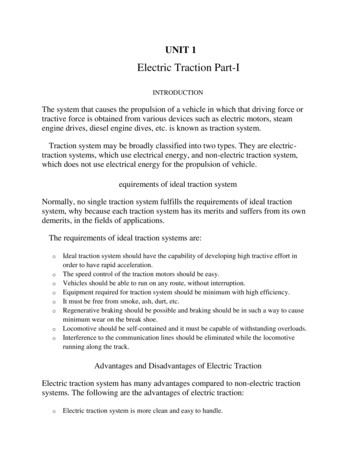
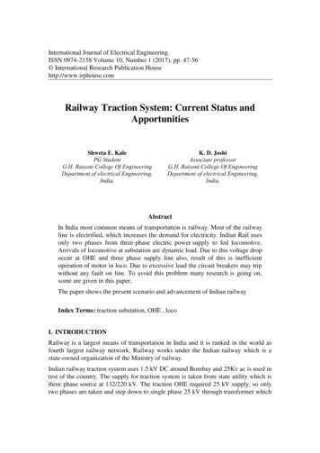
Railway Traction System: Current Status and Apportunities49passenger traffic and 65.02% of freight traffic is operated by electric traction. Thedetailed traction system can be described by dividing it into three sections such asthree phase supply system, traction substation and locomotive system which isdescribed as follows:A.Three phase supply systemThe generated power from generating station is transmitted to the grid substation viathree phase distribution system. The three phase distribution system is at voltage levelof 220 KV or 132 KV from normal. But Indian railway accepted the 25 kv systemtherefore the available three phase voltage has to be step down to 25 kv. The stepdown transformer is connected to any of two phases of normal three phase lines tostep down the 220/132 Kv to 25kv. This causes imbalance and dip in voltage in threephase system. For balancing of the load on the power system, the OHE contact wiresare supplied from A-B, B-C, C-A at regular intervals (about 40-60Km) at tractionsubstation .If one phase is fed from A-B then the next substation is fed from b-cphase. This type of combination of phases does not change the phase sequence of thesystem. To avoid the short circuit between the phase’s neutral section or dead zone isprovided between two consecutive sections which is powered from two different setof phases.Fig. 2 Typical Feeding Arrangement of 25 KV Traction System of Indian Railway.Fig.2 shows, two substations are fed from different phases and in between this bridgeinterrupter is shown. The bridge interrupter is for loco to switch over safely from A-Bphase to B-C phase.B. Traction substationAt traction substation 220/132 kV is step down to 25 kV through single phasetransformer. The 25 kV AC voltage is drawn as single phase system from a threephase systems. One connection of transformer is permanently solidly earthed which
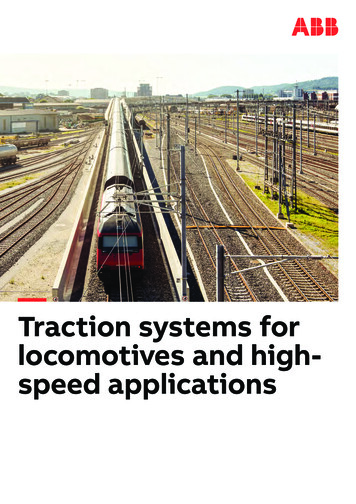
Shweta E. Kale and K. D. Joshi50work as return. The traction substation not only consists of transformer but alsovarious protective devices. It includes lightning arrestor, circuit breaker, transformerprotection etc. This 25 kv is then supplied to the feeder then to the OHE line.Fig.3 Arrangement of Traction SubstationC.Locomotive SubsystemThe power required for propulsion of loco is taken from OHE via pantograph. The ACor DC drives are used for loco. The traction motors used are DC series motor, threephase induction motor. But new locos are come up with three phase induction motor.The induction traction motor has many advantages over dc series motor like highpower at low speed, absence of commutator, VVVF control and regenerative breakingsystem. In today’s scenario WAP7 and WAG9 are the passenger and goods locowhich are mostly used. It consists of transformer, DC link in between line converterand motor converter. The specification given below is from WAP7 manual.specificationTraction transformer25kV – 1269VDC link2800VTraction motor3 phase squirrel cage induction motor 1283/2484 rpmPower outputMax 5100 kW (6000 hP) (1 motor 850kW)
Railway Traction System: Current Status and Apportunities51Fig.4. Block diagram of AC locomotiveIV. PROBLEMS RELATED WITH TRACTION SYSTEMA.Load UnbalancingConventional power system is single phase or three phase system but traction systemis two phase system. This use of two from three phase system causes unbalance inthree phase network. The result of this unbalance is generation of negative phasesequence component besides positive phase sequence component which is harmful forpower system as well as traction system. The control of the load balancer may bebased on the component of the current through them is controlled by simple fact thatthree line to line voltages having the same thyristor valves, giving apparent variableimpedance., means that the different phase sequence components are derived and itwill acts to nullify the negative one.B. Power Quality IssuesPower quality phenomenon related with traction system is voltage fluctuation, voltageand current distortion, voltage sag, harmonics, reactive power and lower power factor.There is uncertainty in arrival and departure of locomotive load at traction substation.If suppose at a time many loco arrives then there is overloading and this causesvoltage drop and dip in voltage which in turn degrades voltage profile as powerdemand depends on loco traffic. Starting, acceleration, deceleration also causes theeffect on voltage profile. Due to this relay actuates even though there is not a fault.Loco subsystem consists of converter which creates harmonics which also contributesto the degradation of voltage profile. Because of this problem traction motor drawslarge amount of current and actuates relay without any fault in traction system.
Shweta E. Kale and K. D. Joshi52V. OPPORTUNITIESTo reduce the tariff it is required to reduce the losses and improve system performance.The compensation scheme can be used to overcome problem in traction system whichare listed above but it should have lower cost and higher efficiency. Voltage support isessential to reduce voltage fluctuation at a given terminal of a line. Advantage ofreactive power compensation in transmission systems is that it improves the stabilityof the ac system by increasing the capacity of maximum active power that can betransmitted.A.Use of FACTS DevicesFlexible AC Transmission Systems (FACTS), uses power electronic devices arewidely used for mitigation of harmonics and sag which will in turn improve quality ofpower and enhancing the traction system reliability. Railway is one of the major loadon the grid. There it is necessary to control the harmonics and voltage fluctuationFACTS-devices provide a better control on reactive power, power factor and improvethe reliability of existing installations. As the length of line increases line losses alsoincreases and need for FACTS also gets important. The FACTS-devices can beswitched or controlled shunt compensation, series compensation. These devices arefast current, voltage or impedance controllers.1) Static VAR Compensator (SVC)Static VAR Compensator (SVC) is shunt connected FACTS devices which gives fastcontrol of reactive power either by absorbing or injecting of reactive power tomaintain voltage level. SVC consists of Thyristor Controlled Reactor(TCR), ThyristorSwitch Capacitor (TSC) and mechanically switch capacitor or inductor harmonicfilter.Fig.5 Structure of SVC
Railway Traction System: Current Status and Apportunities53Advantages SVC in traction system: SVC has the capability of not only compensating the NSC but also reactivepower. To improve voltage profile when one of two f eed er st at io n trips and twosections has to be fed from single station this not only degrades the tractionefficiency and performance. To maintain power factor close to unity.2) STATCOMA STATCOM is a shunt device similar to SVC but it consists of a voltage sourceconverter (VSC) and a coupling transformer, connected in shunt with the AC system.STATCOM is used to improve the system stability by reducing losses and reactivepower compensation [7].Fig.6 Structure of STATCOMCompared with SVC, STATCOM has advantages such as fast speed, gat loading ratehigh work efficiency, and small output harmonic content. STATCOM is frequentlyused for mitigation of voltage flicker. STATCOM reduces the voltage flicker to thefactor, negative phase sequence compensation, improves power factor.A.Dynamic Voltage RegulatorDVR is most widely used series compensation with voltage source to improve voltagesag. DVR boosted the voltage and injects at required phase angle with respect to linevoltage.
54Shweta E. Kale and K. D. JoshiDVR not only compensate line resistance but also reactance by injecting active andreactive power into system.Fig.7 Structure of DVRC. Railway Power ConditionerPower quality phenomenon related with traction system is voltage fluctuation, voltageand current distortion, voltage sag, harmonics, reactive power etc. There is uncertaintyin Railway power conditioner is intentionally used to compensate the negative powercomponent. It consists of back to back converter with a dc link It is able tocompensate the reactive power as well as harmonics.VI. CONCLUSIONAs there is large load on traction system FACTS controller enhances the powertransfer capability of existing line there by reduces the cost for new transmission lineinstallation. SVC and STATCOM provide dynamic voltage support for high powertraction system and prevents it from harmful voltage sag. But STATCOM is moresuperior then SVC. FACTS devices provide voltage control and harmonic reductionof AC supply systems which is due to a converter fed traction.DVR gives better solution to overcome sags in system voltage. Along withcompensation, the DVR and FACTS devices can prevent the false triggering ofprotection relay due to over loading on line. TPC or railway power conditionerperformance better to compensate NSC, harmonics and reactive power,simultaneously
Railway Traction System: Current Status and Apportunities55REFERENCES[1]Dr. V.S.Kale ; Goli Chandra Shekhar “Application of SVC to ImproveVoltage Profile of Indian Railway Traction System”; 2014 IEEE InternationalConference on Power Electronics, Drives and Energy Systems (PEDES).[2]Prashant Singh Rajput, Durga Sharma, “Review and Utility of FACTSController for Traction System” ; International Journal of ScientificEngineering and Technology Research ; Volume.03, IssueNo.11, June-2014,Pages: 2338-2343.hang Ho Jung, Jin-0 Kim[3]J. Martinez IEEE Student member, G. Ramos IEEE member; “Reactive Powerand Harmonic Distortion Control in Electric Traction Systems” ; 2010IEEE/PES Transmission and Distribution Conference and Exposition: LatinAmerica.[4]Lalit G. Patil , “ FACTS in Voltage Profile Improvement of open-loopTraction system” ; Vol-2 Issue-1 2016 IJARIIE-ISSN(O)-2395-4396 1566.[5]Sayed Mohammad Mousavi Gazafrudi, Adel Tabakhpour Langerudy, Ewald F.Fuchs, Kamal Al-Haddad, “Power Quality Issues in Railway Electrification: AComprehensive Perspective’’ , IEEE Transactions on Industrial Electronics,Vol. 62, No. 5, May 2015.[6]Nisarg Raval1, Prof. S.N. Shivani2, Prof. M.K. Kathiria3, “AC TractionPower Line Fault Analysis and Simulation”, international journal of innovativeresearch in electrical, electronics, instrumentation and control engineering Vol.4, Issue 4, April 2016.[7]Seoung Hyuk Lee, In Soo Bae, “A Study on System Stability Improvement ofDistribution System with High Speed Electric Railwav Using STATCOM” ,IEEE, 2003 [8]Dr. V.S.Kale ; Goli Chandra Shekhar “Application of DVR to ImproveVoltage Profile of Indian Railway Traction System”; 2014 IEEE[9]Shubhra ; “MATLAB/Simulink Based Model for 25 kV AC Electric TractionDrive”; International Journal of Engineering Research & Technology (IJERT)Vol. 3, Issue 5, May - 2014[10] Dr. V.S.Kale ; Goli Chandra Shekhar “Application of DVR to ImproveVoltage Profile of Indian Railway Traction System”; 2014 IEEE[11] T.Iswariya, V.Vennila;“ International Conference on Science, Technology,Engineering & Management”; JCHPS Special Issue 10: July 2015[12] Dr. V.S.Kale ; Goli Chandra Shekhar “Application of DVR to ImproveVoltage Profile of Indian Railway Traction System”; 2014 IEEE
56Shweta E. Kale and K. D. Joshi[13] Bhavesh Bhalja, R. P. Maheshwari; “High Speed Protection Scheme forTraction OHE of 25 kV AC Indian Railway System”, 0197-2618, 07, 2007IEEE[14] Amrutha Babu P.Sreejaya; “Reduced Rating Railway Power ConditionersinCo-phase Traction and Traditional Traction System”, InternationalConference on Control, Communication & Computing India (ICCC), 19-21November 2015., 2015 International Conference on Control, Communication& Computing India (ICCC) 19-21 November 2015 Trivandrum 2015International Conference on Control, Communication & Computing India(ICCC) 19-21 November 2015 Trivandrum00 02003 EEE 0-7803-81 IO6/03/ 17.002003 EEE
Indian railway traction system uses 1.5 kV DC around Bombay and 25Kv ac is used in rest of the country. The supply for traction system is taken from state utility which is three phase source at 132/220 kV. The traction OHE required 25 kV supply, so only two phases are taken and step down to single phase 25 kV through transformer which