Transcription
Railway Alignment Design and GeometryPasi Lautala, Michigan Tech UniversityTyler Dick, HDR, Inc.Topics Horizontal andVertical geometry Clearances Turnout design Structures and loading1REES Module #6 - Railway Alignment Design and Geometry1
Railroad vs. Highway –Passenger VehiclesPassenger CarLight rail vehicleTop speed (mph)65 65Weight (tons)1.453.5Power to weight ratio(hp/ton)1509.3Length (ft)1592 (articulated)# of passengers5160Propulsion methodGasoline engineElectric (or dieselelectric)2REES Module #6 - Railway Alignment Design and Geometry2
Railroad vs. Highway –FreightSemi-trailer TruckFreight (Unit) TrainTop speed (mph)55 40 Weight (tons)4018,000Power to weight ratio(hp/ton)12.50.73Length (ft)657,000# of power units11-4# of trailing units1Up to 125Propulsion methodDiesel engineDiesel-electric3REES Module #6 - Railway Alignment Design and Geometry3
Horizontal Geometry – Degree of Curve Arc (Roadway and LRT)– Angle measured alongthe length of a section ofcurve subtended by a100’ arc Chord (Railroad)– Angle measured alongthe length of a section ofcurve subtended by a100’ chord100’100’D RD/360 100/2(pi)R– 1-deg curve, R 5729.58’– 7-deg curve, R 818.51’D RR 50/sin(D/2)– 1-deg curve, R 5729.65’– 7-deg curve, R 819.02’REES Module #6 - Railway Alignment Design and Geometry4
Curve length differenceWatch out for LONG and SHARP curvesREES Module #6 - Railway Alignment Design and Geometry5
Horizontal Geometry –CurvesHighwayRailroadCriteria- Design speed-Design speed-Allowable superelevationTypical valuesFreeway:- 60 mph, R 1,340, D 4.28- 70 mph, R 2,050, D 2.79Main lines:-High speed: R 5,729, D 1-Typical: R 2,865, D 2-Low speed: R 1,433, D 4Industrial facilities:- R 764, D 7.56REES Module #6 - Railway Alignment Design and Geometry6
Horizontal Geometry –SuperelevationHighwayRailroadExpressedby “e” expressed as cross-slope “E” is inches of elevation differencein percentbetween “high rail” (outside) and “lowrail” (inside)Function of Vehicle speed, curve radiusand tire side friction(0.01e f) / (1 – 0.01ef) V2/15RFunction of design speed, degree ofcurveE 0.0007V2D – EuWhere Eu is unbalance (1-2” typical)Max. values6-8%Freight: 6-7”Light Rail: 6”Rotation pointCenterline“Inside rail”TransitionRunoff (2/3 on tangent, 1/3 in Spiralcurve)7REES Module #6 - Railway Alignment Design and Geometry7
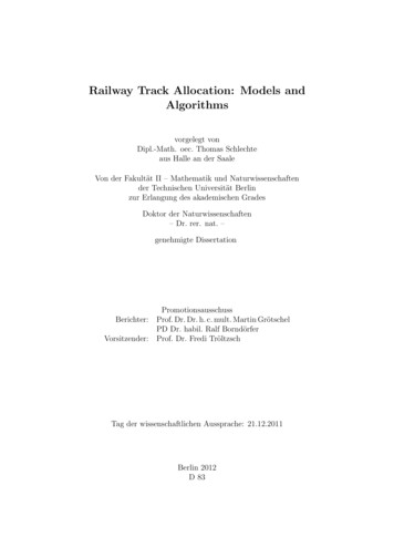
Unbalanced Elevation Different maximumallowed speeds fordifferent trains on thesame track: passenger, expressfreight, general freight Actual elevation ontrack to balance headand flange wear ofboth railsEQUILIBRIUMOVERBALANCECenter rceCenter ofGravityCenter GravityResultantSuperelevationVmax V maxEaDGravitySuperelevationEa 30.0007 DSuperelevationAmount ofUnderbalance Maximum allowable operating speed (mph). Average elevation of the outside rail (inches). Degree of curvature (degrees).
Spiral Transition CurvesTS (Tangent to Spiral)SC (Spiral to Curve)Railways use the higher length of two formulae: To limit unbalanced lateral acceleration acting onpassengers to 0.03 g per second:L 1.63 Eu V Eu unbalanced elevation (in.) To limit track twist to 1 inch in 62 feet:9L 62 EaEa actual elevation (in.)REES Module #6 - Railway Alignment Design and Geometry9
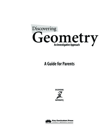
Superelevation TablesREES Module #6 - Railway Alignment Design and Geometry10
Avoid Reversed CurvesMin. 100’ or 3 seconds of runningTime between curves (select greater)!!REES Module #6 - Railway Alignment Design and Geometry11
Critical Issues with Horizontal Curvesa) Too short tangentbetween reversedcurvesb) “Broken back” curvec) Curve within turnoutd) Additionalhorizontal clearancerequired12REES Module #6 - Railway Alignment Design and Geometry12
Vertical Geometry - GradesHighway –4% common6% on rampsUp to 8% oncounty roadsRail – rarely exceeds 1%(2-2.5% for industry lines)LRT – maximum 4 to 6%Up to 10% for short sectionsREES Module #6 - Railway Alignment Design and Geometry13
Design Grade for Railways Ideal maximum for railway grade: Trains can roll safely down 0.3% grade withoutwasting energy on brakes 0.1% for tracks for extensive storage Railway vertical curves – old formula:L D/RD algebraic difference of grade (ft. per 100-ft. station)R rate of change per 100-ft. station 0.05 ft. per station for crest on main track 0.10 ft. per station for sag on main track Secondary line may be twice those for mainlineREES Module #6 - Railway Alignment Design and Geometry14
New Shorter Vertical Curves Old railway formula developed in 1880’s for “hook andpin” couplers in those days Present day couplers can accommodate shorter verticalcurves New formula developed in recent years:L 2.15 V2 D / AV train speed in mphD algebraic difference of grade in decimalA vertical acceleration in ft./sec20.1 ft./ sec2 for freight, 0.6 ft./ sec2 for passengeror transitREES Module #6 - Railway Alignment Design and Geometry15
Critical issues with Vertical Curvesa) Overlapping verticalcurvesb) Avoid loweringexisting tracksc) No vertical curveswithin turnoutsd) Provide additionalclearance in sagcurvese) No vertical curveswithin horizontalspirals16REES Module #6 - Railway Alignment Design and Geometry16
Railroad Turnouts Allows diverging from one track to another Identified by “frog number”NPS1PI Typical frog numbers:– Mainline No.20 or 24– Sidings No.15– Yards and Industry No. 11 Diverging turnout speed 2 x NREES Module #6 - Railway Alignment Design and Geometry17
#8 RH TurnoutREES Module #6 - Railway Alignment Design and Geometry18
#8 – Offsets & layoutREES Module #6 - Railway Alignment Design and Geometry19
Designing a Turnout in Plans Need to know: PS to PI length (B) Angle (C) PS to LLT (A) Draw centerline ofeach track Good to mark PS &LLT No curves and/oradjacent turnoutsbetween PS andLLTLegend:PS Point of SwitchPI Point of intersectionLLT Last long tieAngle C Turnout angleREES Module #6 - Railway Alignment Design and Geometry20
Basic Plan Sheet for Track DesignREES Module #6 - Railway Alignment Design and Geometry21
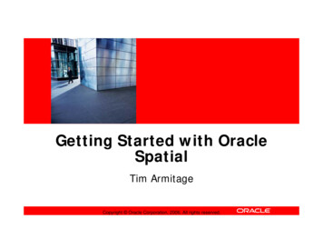
Track Clearances Specific clearancesnecessary for safeoperations Size of car clearanceenvelope is based ondimensions of:– Locomotives– Cars– Potential large loads Requirements set byseveral agencies9’9’23’
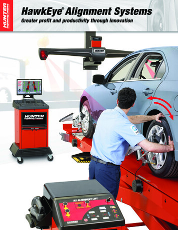
Horizontal Clearance Constant on tangenttrack Additional clearance:– In curves for car endswing and caroverhang– In superelevatedtracks to provideroom for cant Use clearance chart(next page) to definehorizontal clearance for:– Main track– 5.5 degree curve– 2 inch superelevation– 10 feet high objecttruck centers "t"swing out ofcenter line of car fromcenter line of track "m"t/2center line of trackat center of carcar w/2width"w"center line of caroverhang atcenter of car "s"centerof carcentre lineof trackradius of trackcurvature "R"center of curveREES Module #6 - Railway Alignment Design and Geometry23
Clearance ChartREES Module #6 - Railway Alignment Design and Geometry24
Vertical Clearance Constant on tangent track Additional clearance:– In sag vertical curves– In superelevated tracks– For specialized equipment (double-deckcars)– To provide threshold for future trackmaintenance and equipment changesREES Module #6 - Railway Alignment Design and Geometry25
Typical Section - Railroad Subgrade top width of 24’ to 30’ for single track
Typical section - multiple tracks Track centerlines minimum 13’ apart Track centerlines minimum 13’ apart Roadbed sloped to drain Sometimes wider shoulders formaintenance purposes27REES Module #6 - Railway Alignment Design and Geometry27
Bridge Loading - Highway HS-20 truck loading Impact LoadingI 50 / (L 125) but I 0.3REES Module #6 - Railway Alignment Design and Geometry28
Bridge Loading - Railroad Cooper E-80 railroad loading Developed in 1890s “80” refers to 80kip driving axle load on steam locomotiveREES Module #6 - Railway Alignment Design and Geometry29
Bridge Loading – Railroad (cont.) Impact Loading– The following percentages of Live Load, applied atthe top of rail and added to the axle loads (E-80Loading)For L 14 ft: I 60For 14 ft L 127 ft: I 225/ LFor L 127 ft: I 20L Span Length in ftREES Module #6 - Railway Alignment Design and Geometry30
Typical Section – Roadway SuperstructureREES Module #6 - Railway Alignment Design and Geometry31
Typical Section – Railroad ConcreteSuperstructureREES Module #6 - Railway Alignment Design and Geometry32
Grade Separations – Road over Rail 23’ vertical clearance, plus future track raiseAllow for maintenance road and future second trackCollision protection for piers within 25’ of rail centerlineDo not drain roadway on to tracks!Other details vary by specific railroad
Grade Separations – Rail over Road Steel preferred structure type as it can be repaired Concrete bridges - “sacrificial beam” or “crash beam” Depth of structure increases rapidly with span lengthunder railroad loading– Decreases clearance or increase required railroad fill– Need to minimize skew and span lengths
Copyright Restrictions and DisclaimerPresentation AuthorPasi LautalaDirector, Rail Transportation ProgramMichigan Tech UniversityMichigan Tech Transportation Institute318 Dillman HallHoughton, MI 49931(906) 487-3547 ptlautal@mtu.edu It is the author’s intention that the information contained in this file be used for non-commercial, educationalpurposes with as few restrictions as possible. However, there are some necessary constraints on its use asdescribed below.Copyright Restrictions and Disclaimer:The materials used in this file have come from a variety of sources and have been assembled here forpersonal use by the author for educational purposes. The copyright for some of the images and graphicsused in this presentation may be held by others. Users may not change or delete any author attribution,copyright notice, trademark or other legend. Users of this material may not further reproduce this materialwithout permission from the copyright owner. It is the responsibility of the user to obtain such permissionsas necessary. You may not, without prior consent from the copyright owner, modify, copy, publish, display,transmit, adapt or in any way exploit the content of this file. Additional restrictions may apply to specificimages or graphics as indicated herein.The contents of this file are provided on an "as is" basis and without warranties of any kind, either expressor implied. The author makes no warranties or representations, including any warranties of title,noninfringement of copyright or other rights, nor does the author make any warranties or representationregarding the correctness, accuracy or reliability of the content or other material in the file.35REES Module #6 - Railway Alignment Design and Geometry35
REES Module #6 - Railway Alignment Design and Geometry 1 1 Railway Alignment Design and Geometry Pasi Lautala, Michigan Tec