Transcription
Logix 5000 ControllersSequential Function Charts1756 ControlLogix, 1756 GuardLogix, 1769 CompactLogix,1769 Compact GuardLogix, 1789 SoftLogix, 5069CompactLogix, 5069 Compact GuardLogix, Studio 5000Logix EmulateRockwell Automation Publication 1756-PM006K-EN-P - March 2022Supersedes Publication 1756-PM006J-EN-P - September 2020Programming ManualOriginal Instructions
Logix 5000 Controllers Sequential Function ChartsImportant User InformationRead this document and the documents listed in the additional resources section about installation, configuration, andoperation of this equipment before you install, configure, operate, or maintain this product. Users are required to familiarizethemselves with installation and wiring instructions in addition to requirements of all applicable codes, laws, and standards.Activities including installation, adjustments, putting into service, use, assembly, disassembly, and maintenance are required tobe carried out by suitably trained personnel in accordance with applicable code of practice.If this equipment is used in a manner not specified by the manufacturer, the protection provided by the equipment may beimpaired.In no event will Rockwell Automation, Inc. be responsible or liable for indirect or consequential damages resulting from the useor application of this equipment.The examples and diagrams in this manual are included solely for illustrative purposes. Because of the many variables andrequirements associated with any particular installation, Rockwell Automation, Inc. cannot assume responsibility or liability foractual use based on the examples and diagrams.No patent liability is assumed by Rockwell Automation, Inc. with respect to use of information, circuits, equipment, or softwaredescribed in this manual.Reproduction of the contents of this manual, in whole or in part, without written permission of Rockwell Automation, Inc., isprohibited.Throughout this manual, when necessary, we use notes to make you aware of safety considerations.WARNING: Identifies information about practices or circumstances that can cause an explosion in a hazardous environment, which may lead to personal injuryor death, property damage, or economic loss.ATTENTION: Identifies information about practices or circumstances that can lead to personal injury or death, property damage, or economic loss. Attentionshelp you identify a hazard, avoid a hazard, and recognize the consequence.IMPORTANT Identifies information that is critical for successful application and understanding of the product.Labels may also be on or inside the equipment to provide specific precautions.SHOCK HAZARD: Labels may be on or inside the equipment, for example, a drive or motor, to alert people that dangerous voltage may be present.BURN HAZARD: Labels may be on or inside the equipment, for example, a drive or motor, to alert people that surfaces may reach dangerous temperatures.ARC FLASH HAZARD: Labels may be on or inside the equipment, for example, a motor control center, to alert people to potential Arc Flash. Arc Flash will causesevere injury or death. Wear proper Personal Protective Equipment (PPE). Follow ALL Regulatory requirements for safe work practices and for PersonalProtective Equipment (PPE).Rockwell Automation recognizes that some of the terms that are currently used in our industry and in thispublication are not in alignment with the movement toward inclusive language in technology. We areproactively collaborating with industry peers to find alternatives to such terms and making changes to ourproducts and content. Please excuse the use of such terms in our content while we implement these changes.2Rockwell Automation Publication 1756-PM006K-EN-P - March 2022
Summary of changesThis manual includes new and updated information. Use these referencetables to locate changed information.Grammatical and editorial style changes are not included in this summary.Global changesThis table identifies changes that apply to all information about a subject inthe manual and the reason for the change. For example, the addition of newsupported hardware, a software design change, or additional referencematerial would result in changes to all of the topics that deal with that subject.ChangeTopicUpdated Legal notices.Legal notices on page 10Rockwell Automation Publication 1756-PM006K-EN-P - March 20223
Table of ContentsSummary of changesPrefaceStudio 5000 environment . 9Additional resources . 9Legal notices . 10Design a sequential functionchartChapter 1Introduction .13What is a sequential function chart? .13Define the tasks. 16Choose how to execute the SFC . 17Define the steps of the process . 17Step guidelines . 18SFC STEP structure. 19Organize the steps . 21Sequence .23Selection branch .23Simultaneous branch . 24Wire to a previous step . 25Add actions for each step . 25How do you want to use the action? . 26Use a non-Boolean action . 26Use a Boolean action . 27SFC ACTION structure . 28Describe each action in pseudocode . 28Choose a qualifier for an action . 29Define the transition conditions . 30Transition tag . 31How do you want to program the transition? . 31Use a BOOL expression . 31Call a subroutine in a transition .32Transition after a specified time .32Turn off a device at the end of a step . 35Choose a last scan option . 35Use the Don’t Scan option . 37Use the programmatic reset option . 37Use the automatic reset option .39Keep something on from step-to-step . 41How do you want to control the device? . 41Use a simultaneous branch . 41Store and reset an action . 42Use one large step .43End the SFC . 44Rockwell Automation Publication 1756-PM006K-EN-P - March 20225
Table of ContentsUse a stop element . 44Restart (reset) the SFC .45SFC STOP structure . 46Nest an SFC . 46Pass parameters .47Configure when to return to the OS/JSR . 48Pause or reset an SFC . 48Execution diagrams . 48Program a sequential functionchart6Chapter 2Introduction . 53Add and manually connect elements . 53Add and automatically connect elements . 54Drag elements .54Create a simultaneous branch .54Start a simultaneous branch .54End a simultaneous branch .55Create a selection branch .56Start a selection branch .56End a selection branch .56Set the priorities of a selection branch . 57Connect a wire to the step . 58Hide a wire . 58Configure a step .59Assign the preset time for a step .59Configure alarms for a step .59Use an expression to calculate a time . 60Program a transition . 61Enter a BOOL expression . 61Call a subroutine when programming a transition. 61Add an action . 62Configure an action. 62Change the qualifier of an action. 62Calculate a preset time at runtime .63Mark an action as a BOOLean action .63Program an action .63Enter structured text . 64Call a subroutine in an action . 64Assign the execution order of actions .65Document an SFC.65Language switching . 66Add structured text comments . 66Rockwell Automation Publication 1756-PM006K-EN-P - March 2022
Table of ContentsAdd a tag description .67Add a text box .67Show or hide text boxes or tag descriptions . 68Hide an individual tag description . 68Configure the execution of the SFC . 69Verify the routine . 69Edit an SFC online . 70Maintain active SFC step . 70Force stepsIndexChapter 3Introduction . 71Precautions . 71Enable forces . 71Disable or remove a force . 72Check force status . 72Force LED. 73GSV instruction . 73Step through a transition or a force of a path . 73When to use an SFC force .74Force a transition .74Force a simultaneous path. 75Add an SFC force .76Remove or disable forces . 77Disable all SFC forces . 77Remove all SFC forces . 77Rockwell Automation Publication 1756-PM006K-EN-P - March 20227
PrefaceThis manual shows how to design and program Sequential Function Charts(SFCs) for Logix 5000 controllers to execute. This manual is one of a set ofrelated manuals that show common procedures for programming andoperating Logix 5000 controllers.For a complete list of common procedures manuals, refer to the Logix 5000Controllers Common Procedures Programming Manual, publication1756-PM001.The term Logix 5000 controller refers to any controller based on the Logix5000 operating system.Studio 5000 environmentThe Studio 5000 Automation Engineering & Design Environment combinesengineering and design elements into a common environment. The firstelement is the Studio 5000 Logix Designer application. The Logix Designerapplication is the rebranding of RSLogix 5000 software and will continue tobe the product to program Logix 5000 controllers for discrete, process,batch, motion, safety, and drive-based solutions.The Studio 5000 environment is the foundation for the future ofRockwell Automation engineering design tools and capabilities. The Studio5000 environment is the one place for design engineers to develop allelements of their control system.Additional resourcesThese documents contain additional information concerning relatedRockwell Automation products.ResourceDescriptionLogix 5000 Controllers Program ParametersProgramming Manual, publication 1756-PM021Describes how to use program parameters whenprogramming Logix 5000 controllers.Rockwell Automation Publication 1756-PM006K-EN-P - March 20229
PrefaceResourceDescriptionLogix 5000 Controllers General Instructions ReferenceManual, publication 1756-RM003Describes the available instructions for a Logix 5000controller.Logix 5000 Controllers Process and Drives InstructionsReference Manual, publication 1756-RM006Logix 5000 Controllers Motion Instruction Set ReferenceManual, publication MOTION-RM002Describes how to program a Logix 5000 controller forprocess or drives applications.Describes how to program a Logix 5000 controller formotion applications.Product Certifications website,http://ab.rockwellautomation.comProvides declarations of conformity, certificates, andother certification details.You can view or download publications athttp://www.rockwellautomation.com/literature. To order paper copies oftechnical documentation, contact your local Rockwell Automation distributoror sales representative.Legal noticesRockwell Automation publishes legal notices, such as privacy policies, licenseagreements, trademark disclosures, and other terms and conditions on theLegal Notices page of the Rockwell Automation website.End User License Agreement (EULA)You can view the Rockwell Automation End User License Agreement (EULA)by opening the license.rtf file located in your product's install folder on yourhard drive.The default location of this file is:C:\Program Files (x86)\Common Files\Rockwell\license.rtf.Open Source Software LicensesThe software included in this product contains copyrighted software that islicensed under one or more open source licenses.You can view a full list of all open source software used in this product andtheir corresponding licenses by opening the oss license.txt file located in yourproduct's OPENSOURCE folder on your hard drive. This file is divided intothese sections: ComponentsIncludes the name of the open source component, its version number,and the type of license. Copyright TextIncludes the name of the open source component, its version number,and the copyright declaration.10Rockwell Automation Publication 1756-PM006K-EN-P - March 2022
Preface LicensesIncludes the name of the license, the list of open source componentsciting the license, and the terms of the license.The default location of this file is:C:\Program Files (x86)\Common Files\Rockwell\Help\ productname \Release Notes\OPENSOURCE\oss licenses.txt.You may obtain Corresponding Source code for open source packagesincluded in this product from their respective project web site(s).Alternatively, you may obtain complete Corresponding Source code bycontacting Rockwell Automation via the Contact form on the RockwellAutomation bout-us/contact/contact.page.Please include "Open Source" as part of the request text.Rockwell Automation Publication 1756-PM006K-EN-P - March 202211
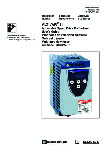
Chapter 1Design a sequential function chartIntroductionA sequential function chart (SFC) is similar to a flowchart of your process. Itdefines the steps or states through which your system progresses. It helps youdo the following: Organize the functional specification for your system. Program and control your system as a series of steps and transitions.By using an SFC to specify your process, you gain these advantages. Since an SFC is a graphical representation of your process, it is easierto organize and read than a textual version. Add notes that clarify steps or capture important information foruse later on. Print the SFC to share the information with other individuals. Since Logix 5000 controllers support SFCs, you do not have to enterthe specification a second time. You are programming your system asyou specify it.By using an SFC to program your process, you gain these advantages. What is a sequentialfunction chart?Graphical division of processes into its major logic pieces (steps)Faster repeated execution of individual pieces of your logicSimpler screen displayReduced time to design and debug your programFaster and easier troubleshootingDirect access to the point in the logic where a machine faultedEasy updates and enhancementsA sequential function chart (SFC) is similar to a flowchart. It uses steps andtransitions to perform specific operations or actions. This example shows theelements of an SFC. The SFC continues on the following page.Rockwell Automation Publication 1756-PM006K-EN-P - March 202213
Chapter 1Design a sequential function chartA step represents a major function of your process. It contains the actions that occur at a particular time,phase, or station.An action is one of the functions that a step performs.A transition is the TRUE or FALSE condition that tells the SFC when to go to the next step.A qualifier determines when an action starts and stops.A simultaneous branch executes more than 1 step at the same time.JSR instruction calls a subroutine.14Rockwell Automation Publication 1756-PM006K-EN-P - March 2022
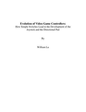
Chapter 1Design a sequential function chartA selection branch chooses between different execution paths.A text box lets you add descriptive text or notes to your SFC.Rockwell Automation Publication 1756-PM006K-EN-P - March 202215
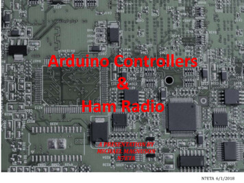
Chapter 1Design a sequential function chartA wire connects one element to another element anywhere on the chart. This wire takes you to the conveyorstep on the first part of this SFC (previous figure).A stop lets you stop and wait for a command to restart.Follow these steps to design a sequential function chart.1. Define the tasks on page 162. Choose how to execute the SFC on page 173. Define the steps of the process on page 174. Organize the steps on page 215. Add actions for each step on page 256. Describe each action in pseudocode on page 287. Choose a qualifier for an action on page 298. Define the transition conditions on page 309. Transition after a specified time on page 3210. Turn off a device at the end of a step on page 3511. Keep something on from step-to-step on page 4112. End the SFC on page 4413. Nest an SFC on page 4614. Configure when to return to the OS/JSR on page 4815. Pause or reset an SFC on page 4816. Execution diagrams on page 48Define the tasksThe first step in the development of an SFC is to separate the configurationand regulation of devices from the commands to those devices. Logix 5000controllers let you divide your project into one continuous task and multipleperiodic tasks and event tasks.To define the tasks1. Organize your project.These functionsGo into this type of task Configure and regulate devicesPeriodic task Command a device to a specific state Sequence the execution of your processSFC in the continuous task2. For those functions that go in a periodic task, group the functionsaccording to similar update rates. Create a periodic task for eachupdate rate.For example, 2-state devices may require faster updates than PIDloops. Use separate periodic tasks for each.In this example, a project uses two periodic tasks to regulate motors,valves, and temperature loops. An SFC controls the process.Define the Tasks:16Rockwell Automation Publication 1756-PM006K-EN-P - March 2022
Chapter 1Design a sequential function chartThis task (periodic) uses Function Block diagrams to turn on or offmotors and open or close valves. The SFC in MainTask commands thestate for each device. The Function Block diagrams set and maintainthat state.This task (periodic) uses Function Block diagrams to configure andregulate temperature loops. The SFC in MainTask commands thetemperatures. The Function Block diagrams set and maintain thosetemperatures.This task (continuous) executes the sequential function chart (SFC). TheSFC commands the specific state or temperature for each device ortemperature loop.Choose how to execute theSFCTo execute an SFC, either configure it as the main routine for a program orcall it as a subroutine.IfThen The SFC is the only routine in the program The SFC calls all the other routines of the program The program requires other routines to executeindependent of the SFC The SFC uses Boolean actionsConfigure the SFC as the main routine for the program.1. Configure another routine as the main routine for theprogram.2. Use the main routine to call the SFC as a subroutine.If the SFC uses Boolean actions, then other logic must run independent of theSFC and monitor status bits of the SFC.Define the steps of theprocessA step represents a major function of your process. It contains the actionsthat occur at a particular time, phase, or station.A transition ends a step. The transition defines the physical conditions thatmust occur or change in order to go to the next step.Rockwell Automation Publication 1756-PM006K-EN-P - March 202217
Chapter 1Design a sequential function chartStep guidelinesFollow these guidelines. Start with large steps and refine the steps in several passes. When you first open an SFC routine, it contains an initial step andtransition. Use this step to initialize your process.The controller executes the initial step in these situations. After a project download when the controller goes into Run mode. When the controller transitions to Run mode and on power-up (ifthe SFC is configured for that). When the routine containing the chart is modified online and areset is required, and the controller transitions to or from Testmode. To identify a step, look for a physical change in your system, such asnew part that is in position, a temperature that is reached, a presettime that is reached, or a recipe selection that occurs. The step is theactions that take place before that change. Stop refining the steps when they are in meaningful increments. Thisis an example.18This organization of stepsIsproduce solutionProbably too largeset mode, close outlet, set temperature, open inlet a, close inlet a,set timer, reset temperature, open outlet, reset modeProbably too smallpreset tank, add ingredient a, cook, drainProbably about rightRockwell Automation Publication 1756-PM006K-EN-P - March 2022
Chapter 1SFC STEP structureDesign a sequential function chartEach step uses a tag to provide information about the step. Access thisinformation with either the Step Properties dialog box or the Monitor Tagstab of the Tags window.If you want toThen select or set this Data typememberDetailsDetermine how long a step has beenactive (milliseconds)TDINTWhen a step becomes active, the Timer (T) value resets and then starts to count upin milliseconds. The Timer continues to count up until the step goes inactive,regardless of the Preset (PRE) value.DINTEnter the time in the Preset (PRE) member. When the Timer (T) reaches the Presetvalue, the Done (DN) bit turns on and stays on until the step becomes active again.As an option, select Use Expression and click Define to enter a numeric expressionthat calculates the time at runtime.DNBOOLWhen the Timer (T) reaches the Preset (PRE) value, the Done (DN) bit turns on andstays on until the step becomes active again.LimitLowDINTEnter the time in the Limit Low (LimitLow) member (milliseconds). If the step goes inactive before the Timer (T) reaches the LimitLow value, theAlarmLow bit turns on. The AlarmLow bit stays on until you reset it. To use this alarm function, turn on (select) the Alarm Enable (AlarmEn) bit.As an option, enter a numeric expression that calculates the time at runtime.AlarmEnBOOLTo use the alarm bits, turn on (select) the Alarm Enable (AlarmEn) bit.AlarmLowBOOLIf the step goes inactive before the Timer (T) reaches the Limit Low value, theAlarmLow bit turns on. The bit stays on until you reset it.To use this alarm function, turn on (select) the Alarm Enable (AlarmEn) bit.LimitHighDINTEnter the time in the Limit High member (milliseconds). If the Timer (T) reaches the LimitHigh value, the AlarmHigh bit turns on. The AlarmHigh bit stays on until you reset it. To use this alarm function, turn on (select) the Alarm Enable (AlarmEn) bit.As an option, enter a numeric expression that calculates the time at runtime.AlarmEnBOOLTo use the alarm bits, turn on (select) the Alarm Enable (AlarmEn) bit.AlarmHighBOOLIf the Timer (T) reaches the Limit High value, the AlarmHigh bit turns on. The bit stayson until you reset it.To use this alarm function, turn on (select) the Alarm Enable (AlarmEn) bit.Do something while the step is active(including first and last scan)XBOOLThe X bit is on the entire time the step is active (executing).Typically, we recommend that you use an action with a N Non-Stored qualifier toaccomplish this.Do something one time when the stepbecomes activeFS1BOOLThe FS bit is on during the first scan of the step.Typically, we recommend that you use an action with a P1 Pulse (RisingEdge) qualifier to accomplish this.Set a flag when the step has been active PREfor a specific length of time (milliseconds)Set a flag if a step did not execute longenoughSet a flag if a step is executing too longRockwell Automation Publication 1756-PM006K-EN-P - March 202219
Chapter 1Design a sequential function chartIf you want toThen select or set this Data typememberDetailsDo something while the step is active,except on the first and last scanSABOOLThe SA bit is on when the step is active except during the first and last scan of thestep.Do something one time on the last scan of LS1the stepBOOLThe LS bit is on during the last scan of the step.Use this bit only if on the Controller Properties dialog box, SFC Execution tab, you setthe Last Scan of Active Step to Don’t Scan or Programmatic reset.Typically, we recommend that you use an action with a P0 Pulse (FallingEdge) qualifier to accomplish this.Determine the target of an SFC Reset(SFR) instructionRe
This manual shows how to design and program Sequential Function Charts (SFCs) for Logix 5000 controllers to execute. This manual is one of a set of related manuals that show common procedures for programming and operating Logix 5000 controllers. For a complete l