Transcription
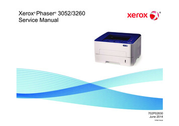
dsoy dk;Zky;hu mi;ksx gsrq(For Official Use Only)Hkkjr ljdkj GOVERNMENT OF INDIAjsy ea ky; MINISTRY OF RAILWAYSBOOKLETONTRACTION MOTOR & GEAR BOXOF TRAIN SETEnd User :Train Set Maintenance StaffCAMTECH/ E/ 2019-20/ EP-05/ TM of Train set/ 1.0December, 2019Maharajpur, GWALIOR - 474 005
BOOKLETONTRACTION MOTOR & GEAR BOXOF TRAIN SETQUALITY POLICY(DRAFT)“We at RDSO Lucknow are committed to maintain andupdate transparent standards of services to develop safe,modern and cost effective railway technologycomplying with statutory and regulatory requirements,through excellence in research, designs and standards bysetting quality objectives, commitment to satisfyapplicable requirements and continual improvements ofthe quality management system to cater to growingneeds, demand and expectations of passenger and freighttraffic on the railways through periodic review of qualitymanagement systems to achieve continual improvementand customer appreciation. It is communicated andapplied within the organization and making it availableto all the relevant interested parties”.
FOREWORDTrain set (Vande Bharat Express/ Train 18) is the concept of multi-unit distributedtraction for main line train operations like Electric Multiple Units (EMUs) and Diesel ElectricMultiple Units (DEMUs) already in service for sub-urban services.Train-set is a set of rail coaches coupled mechanically and electrically with driving cabsat both ends and distributed traction power across the coaches. In Train Set, 50% coaches arepowered coaches i.e. motor coaches.The most important advantage of high-speed train set is the weight reduction effect. Inthis, the traction system equipment is distributed over a train-set, and tractive axles throughoutthe train-set can obtain the required tractive effort without executing a heavy axle load. As aresult, the maximum axle load is reduced.Train set coaches are equipped with modern bolster-less design bogies with fullysuspended three phase AC asynchronous traction motors.To ensure wide dissemination of knowledge on Train Sets and its traction equipment,CAMTECH, Gwalior has prepared this booklet on “Traction Motor and Gear Box of TrainSet”.I am sure that this booklet will be useful for field maintenance staff of Train Set in theirday to day working and improving the reliability and safety of coaching stock on IndianRailways.CAMTECHDate: 31.12.2019Jitendra SinghPrincipal Executive Director
PREFACETrain-set is a set of rail coaches coupled mechanically and electrically with driving cabsat both ends and distributed traction power across the coaches. In Train Set, 50% coaches arepowered coaches i.e. motor coaches.The distributed power train-sets have lighter axle loads, allowing operation on lightertracks, where locomotives may be prohibitive of higher axle loads. Another side effect of this isreduced track wear, as traction forces can be provided through many axles, rather than just thefour or six of a locomotive.All propulsion equipment and power components such as traction motors, line &traction converters, auxiliary converter, air compressor, battery box, battery charger, brakechopper resister are mounted under the frame.Train set coaches are equipped with modern bolster-less design bogies with fullysuspended traction motors, pneumatic secondary suspension and anti-roll bar.Train set is provided with IGBT based energy efficient 3 phase propulsion system andregenerative braking. In each basic unit of four cars, there are two motor coaches (MCs) andtwo trailer coaches (TC, NDTC or DTC).This booklet on "Traction Motor and Gear Box of Train Set” is prepared with theobjective to disseminate knowledge on the subject. This booklet contains general description ofTrain Set, three phase propulsion system, brief on traction motor and gear box etc. This alsocomprises OEM’s recommended preventive maintenance schedules and spares to be kept atmaintenance depots.It is clarified that this booklet does not supersede any existing provisions laid down byRailway Board/ RDSO, OEMs. This handbook is for guidance only and it is not a statutorydocument.I am sincerely thankful to RDSO/ UTHS directorate, OEM M/s Medha Servo DrivesPvt. Ltd., Hyderabad, and all field personnel who helped us in preparing this booklet.Technological up-gradation & learning is a continuous process. Please feel free to write us forany addition/ modification in this handbook.CAMTECH, GwaliorDate: 27.12.2019Manoj KumarJoint Director /Mechanical
CONTENTChapter No1.2.3.DescriptionPage no.ForewordPrefaceContentsCorrection SlipAbbreviationsiiiivvviiviiiGENERAL DESCRIPTION011.0INTRODUCTION011.1IMPORTANT TECHNICAL DETAILS021.2CONFIGURATION AND PROPULSION SYSTEM021.3DISTRIBUTION OF EQUIPMENT031.4DRIVING TRAILER COACH (DTC)031.5MOTOR COACH (MC)041.6TRAILER COACH (TC)041.7NON DRIVING TRAILER COACH (NDTC)053 PHASE AC PROPULSION SYSTEM062.0POWER SCHEMATIC OF TRAIN SET062.1TRACTION TRANSFORMER062.2LINE AND TRACTION CONVERTER (LTC)2.2.1 Line Converter2.2.2 Traction Inverter2.2.3 Line & Traction Control Unit (LTCU)07090909TRACTION MOTOR AND GEAR DRIVE103.0TRAIN SET PARAMETERS103.1TECHNICAL DATA OF TRACTION MOTOR103.2CONSTRUCTIONAL DETAILS OF TRACTION MOTOR3.2.1 Main assemblies of drive complete3.2.2 Stator3.2.3 Rotor3.2.4 Motor connections3.2.5 Traction Motor bearing3.2.6 Motor Cooling3.2.7 Speed sensor3.2.8 Pt100 temperature sensors3.2.9 Traction Motor Water Flood Level111212121313141415153.3TECHNICAL DATA FOR GEAR BOX16
Chapter NoDescriptionPage no.3.4CONSTRUCTIONAL DETAILS OF GEAR BOX3.4.1 Drive Complete3.4.2 Gearbox Description3.4.3 Motor Coupling3.4.4 Connection Gearbox to Wheel Set3.4.5 Gear box Housing3.4.6 Gearbox Support3.4.7 Bearings3.4.8 Lubrication and cooling3.4.9 Sealing3.4.10 Monitoring of the Gearbox16171818191919202020213.5TRACTION MOTOR PREVENTIVE MAINTENANCE SCHEDULE223.5.1 Traction Motor Required Consumable During Maintenance Schedule233.5.2 Traction Motor Spare Parts / Rake Needs To Be Kept At Train Set Depot 233.6TRACTION GEAR BOX PREVENTIVE MAINTENANCE SCHEDULE3.6.1 Gear box oil filling & draining3.6.2 Consumable during maintenance schedule Traction Gear drive system3.6.3 Gear Drive System : Spare Parts / Rake Needs to be Kept atTrain Set Depot3.6.4 Gear Oil-Limits for Contaminations242525REFERENCES282627
ISSUE OF CORRECTION SLIPThe correction slips to be issued in future for this booklet will benumbered as follows:CAMTECH/E/ 2019-20/ EP-05/TM of Train Set/1.0/ C.S. # XX date--Where “XX” is the serial number of the concerned correction slip(starting from 01 onwards).CORRECTION SLIPS ISSUEDSr.No.Date of IssuePage no. & Item no.modifiedRemarks
ABBREVIATIONSAbbreviationDetailsACAlternating CurrentATCAuxiliary Traction ControlBCHBrake ChopperBEBraking effortBUBasic UnitDCDirect CurrentDCLVDC Link VoltageDCS KeyDriver control Switch KeyDEDriving EndDEMUDiesel Electric Multiple UnitsDTCDriving Trailer CoachEBLEmergency Brake LoopEBUEnd Basic UnitEDElectro DynamicELDEarth Leakage DetectorEMUElectric Multiple UnitsEPElectro PneumaticFQCFour Quadrant ConverterHWTLHard Wired Train LineICFIntegral Coach FactoryIECInternational Electro technical CommissionIGBTIntegrated Gate Bipolar TransistorIRIndian RailwaysIVInter VehicularLCLine ConverterLTCLine and Traction ConverterLTCULine & Traction Control UnitMAEMedha AC-EMU
AbbreviationDetailsMBUMiddle Basic UnitMCMotor CoachMCBMiniature Circuit BreakerMCHMaster Control HandleMCUMain Control UnitMMIMan Machine InterfaceMSDPLMedha Servo Drives Pvt. Ltd.MUMultiple UnitMVBMultifunction Vehicle BusNDENon Driving EndNDTCNon Driving Trailer CoachPSPower SupplyPWMPulse Width ModulationRDSOResearch Design and Standards OrganizationRPMRevolution per MinuteTCTrailer CoachTCMSTrain Control & Management SystemTETractive EffortTITraction InverterTMTraction MotorTSATRAKTIONS System AustriaUICInternational Union of RailwaysVCBVacuum Circuit BreakerVVVFVariable Voltage Variable Frequency
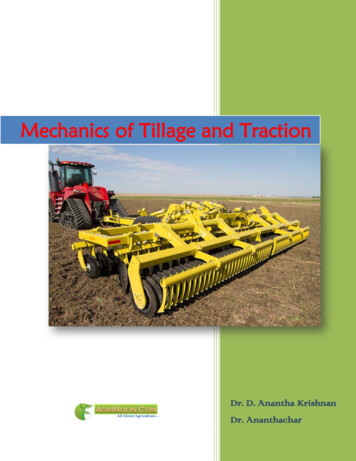
CAMTECH/E/2019-20/EP-05/TM of Train Set/1.01CHAPTER 1GENERAL DESCRIPTION1.0INTRODUCTIONTrain set is the concept of multi-unit distributed traction for main line trainoperations like Electric Multiple Units (EMUs) and Diesel Electric Multiple Units(DEMUs) already in service for sub-urban services.Train-set is a set of rail coaches coupled mechanically and electrically with drivingcabs at both ends and distributed traction power across the coaches. Depending on therequirement, the amount of power i.e. number of powered coaches can generally vary from50% to 100%. In Train Set, 50% coaches are powered coaches i.e. motor coaches.The distributed power train-sets have lighter axle loads, allowing operation onlighter tracks, where locomotives may be prohibitive of higher axle loads. Another sideeffect of this is reduced track wear, as traction forces can be provided through many axles,rather than just the four or six of a locomotive.Fig-1: Train Set (Vande Bharat Express)The most important advantage of high-speed train set is the weight reduction effect.In this, the traction system equipment is distributed over a train-set, and tractive axlesthroughout the train-set can obtain the required tractive effort without executing a heavyaxle load. As a result, the maximum axle load is reduced.All propulsion equipment and power components such as traction motors, line &traction converters, auxiliary converter, air compressor, battery box, battery charger, brakechopper resister are mounted under the frame.Train set coaches are equipped with modern bolster-less design bogies with fullysuspended traction motors, pneumatic secondary suspension and anti-roll bar.Booklet on Traction Motor & Gear Box of Train SetDecember, 2019
21.11.2CAMTECH/E/2019-20/EP-05/TM of Train Set/1.0IMPORTANT TECHNICAL DETAILSParticularsNumber of Coaches in Basic UnitDetails4 car per Basic Unit (BU)DTC-MC-TC-MC (End BU)NDTC-MC-TC-MC (Middle BU)Train formation16 coaches- 4 BU per train% Motoring50%Maximum test speed176 kmphMaximum service speed160 kmphTypical alloutrun8 kmAverage acceleration from 0-40 kmph0.8 m/sec2Deceleration0.8 m/sec2CONFIGURATION AND PROPULSION SYSTEM The Train Set consists of four basic units of four coaches each. The configuration of end basic unit is as follows - DTC MC TC MCFig-2: End Basic Unit The configuration of middle basic unit is as follows - NDTC MC TC MCFig-3: Middle Basic UnitWhereDTC : Driving Trailer CoachTC: Trailer CoachMC :Motor CoachNDTC :Non-Driving Trailer CoachTrain set is provided with IGBT based energy efficient 3phase propulsion systemand regenerative braking. In each basic unit of four cars, there are two motor coaches(MCs) and two trailer coaches (TC, NDTC or DTC).Complete propulsion system is supplied by M/s Medha for the first prototype 16 cartrain set. The fully suspended traction motor is developed by M/s Medha along with M/s.TRAKTIONS SYSTEME AUSTRIA (TSA) and M/s ECE Engineering, Poland.December, 2019Booklet on Traction Motor & Gear Box of Train Set
CAMTECH/E/2019-20/EP-05/TM of Train Set/1.03Total 16 Car Formation – 4 X 4 Basic Units - Each Basic Unit with Four CarsFig:16 Car FormationFig-4: 16 Car Formation1.3DISTRIBUTION OF EQUIPMENTDistributions of equipment among various coaches of train set areas follows:DescriptionDTCUnder-frame - compressor, battery, battery chargerNDTCUnder-frame - compressor, battery, battery chargerMCUnder-frame- line and traction converter, traction motor and geardrive assembly, brake chopper resistorTCUnder-frame - traction transformer, auxiliary converterRoof - Pantograph, VCBALLCoaches1.4Equipment Brake skid (End & Middle), and isolating transformer for pantry load.Under slung water tank capacity 1200Lts approx.Pre wired Cables trays on under frame for power and control cables.Roof mounted packaged unit (RMPU) at both ends on each coachDRIVING TRAILER COACH (DTC)It is a non-powered vehicle with a driver cab at one end. The driver cab is furnishedwith a pre-fabricated driver desk. All driving operations are possible from driver desk.Feedback from all system in all the coaches / basic units is available for viewing on thedriver desk. For this 10.4” touch based TFT display is provided on driver desk for showingcombined status.Various gauges are also provided on driver desk for knowing MR, BP, BC andparking brake pressure. The driver will also be able to control the Passenger InformationSystem (PIS) from the driver desk.Booklet on Traction Motor & Gear Box of Train SetDecember, 2019
4CAMTECH/E/2019-20/EP-05/TM of Train Set/1.0It also consists of battery box, battery charger and compressor mounted under-slung.Rest of the DTC apart from the driver cab is passenger saloon area, which consists ofpantry, RMPU control unit, mono block pump controller, CRW, GCRW panel and variousend wall panels. It is an air-conditioned coach. All passenger comfort related load can becontrolled by driver from driver cab.Fig-5: Driving Trailer Coach (DTC) internal &external view1.5MOTOR COACH (MC)Motor coach is a poweredvehicle with four axles each equipped with a 3phase asynchronous Traction Motor (TM).Traction motors are fully suspended i.e.traction motor weight is not loaded on to thewheel directly. This reduces the un-sprungmass, resulting in better ride comfort.The motor coach consists of two Lineand Traction Converter units (LTC), one foreach bogie mounted under-slung.Brakechopper resistor is also mounted under-slung.Transformer secondary cable for both LTCunits from power transformer come fromtrailer coach through under-slung mounted IVcoupler.It also consists of passenger saloonarea, pantry, RMPU, mono block pumpcontroller, electrical cabinet and various endwall panels. It is an air-conditioned coach.Fig-6: Motor Coach (MC) internal &external view1.6TRAILER COACH (TC)Trailer coach has the pantograph for current collection, vacuum circuit breaker andHV isolator mounted on the roof. For operation of the 16 car, two pantographs will be used.It also consists of auxiliary converter unit and power transformer mounted underslung. Power to LTC units of both motor coaches is distributed from same powertransformer. Auxiliary converter feeds the hotel load of four coaches. It also consists ofDecember, 2019Booklet on Traction Motor & Gear Box of Train Set
CAMTECH/E/2019-20/EP-05/TM of Train Set/1.05passenger saloon area, pantry, RMPU, mono block pump controller, electrical cabinet andvarious end wall panels. It is an air-conditioned coach.Fig-7: Pantograph and RMPU on Trailer Coach (TC)1.7NON DRIVING TRAILER COACH (NDTC)It is similar to DTC except driver related interface. It also consists of battery box,battery charger and compressor mounted under-slung. It also consists of passenger saloonarea which consists of pantry, RMPU control unit, mono-block pump controller, CRW,GCRW panel and various end wall panels. It is also an air-conditioned coach.Booklet on Traction Motor & Gear Box of Train SetDecember, 2019
6CAMTECH/E/2019-20/EP-05/TM of Train Set/1.0CHAPTER 23 PHASE AC PROPULSION SYSTEM2.0POWER SCHEMATIC OF TRAIN SETBelow figure shows the block diagram of the power schematic of the train set.25 kV AC Overhead Line (OHE)PantographCircuit BreakerDC - ACMotor ConverterTransformer2 x 3 Phase MotorsAC - DCConverterTransformer3 Phase AC OutputDC - ACAuxiliary ConverterBatteryDC OutputTransformerAC - DC Rectifier2 x 3 Phase MotorsAC - DCConverterDC - ACMotor Converter- ve return through wheel and running railAxle BrushFig-8: Block Diagram of Electronic Power and Auxiliary ServicesThe 25kV OHE voltage is connected to the transformer primary winding through thepantograph and Vacuum Circuit Breaker (VCB). During maintenance when transformerprimary winding is not connected to the OHE line, an earthing switch (connected in parallelto VCB) is used to ground the transformer primary winding and pantograph for safety.2.1TRACTION TRANSFORMERTraction transformer is mounted under slung of trailer coach (TC).There are 1 primarywinding, 4 traction windings and 2 auxiliary windings in traction transformer. Onetransformer feeds to two motor coaches. Traction transformer is oil cooled with help of oilpump and blower which cool the radiator through which oil is circulated using the oil pump.Important parameters of traction transformer are:December, 2019 Continuous voltage: 19 – 27.5 kV 3 Frequency range: 47 – 53 Hz Total transformer continuous rating is 2880 kVA under 22.5 kV OHE voltage. Each traction winding continuous rating is 603 kVABooklet on Traction Motor & Gear Box of Train Set
CAMTECH/E/2019-20/EP-05/TM of Train Set/1.07 Each auxiliary winding continuous rating is 234 kVA Peak power rating is 3616 kVA, each traction secondary peak rating is 787kVA and auxiliary is 234 kVA. Total approximate weight of transformer is 4900 /-3% kgs.Line ConverterLine ConverterLine ConverterHigh VoltageLine ConverterAux. ConverterAux ConverterFig-9: Block diagram of Traction Transformer windingsFigure : Block diagram of Traction Transformer2.2LINE AND TRACTION CONVERTER (LTC)Each motor coach has 2 nos. of Line and Traction Converters (LTC) mountedunder slung and each control two traction motors of a bogie. Input power to line convertercomes from transformer kept in adjacent trailer coach. Line and traction converters areforced air cooled. Each traction converter cubicle consists of one-line converter, DC link,one traction inverter and line & traction control unit.Fig-10:Line and Traction ConverterImportant parameters of LTC are:Input voltageInput currentWeightDimensionLine and traction converter ratingBooklet on Traction Motor & Gear Box of Train Set:::::950 V AC at 25 kV AC639 A 800 /-50 Kg2250*1220*700 mm554 KVADecember, 2019
8December, 2019Brake Chopper Resistor AssemblyHEAT SINK - 1P8P7HEAT SINK - 2HEAT SINK - 3HEAT SINK - 4 - OHE-PT2-Q61Q3Q4R2CT1- -Q7P3TM1CT3P4Q8P5PT1Q11Q12Q15Q16 TM2-CT4R1ESWBrake Chopper Resistor AssemblyP7HEAT SINK - 2HEAT SINK - 3HEAT SINK - 4 HEAT SINK - 1P8-R5-PT2P1-Q5Q6Q4Q7Q8Q13Q14 -CT3 1Q3R2CT11P3TM1P4CT2P5PT1Q11R6K2R1Q12Q15Q16 -CT4 P2Q2Q10- Q1K1-1Q9C4 PT2Q14-HVCT-2HIGH VOLTAGE EQUIPMENTFig-11 :Power Schematic of Train 18 with emphasis on Traction Converters in Motor CoachTM2CAMTECH/E/2019-20/EP-05/TM of Train Set/1.0Booklet on Traction Motor & Gear Box of Train Set -PT1Q13R6K2TRACTION TRANFORMER HVPTQ10CT21P2Q9 Q5- P1Q1K1-1R5C4 HVCT1Q2
CAMTECH/E/2019-20/EP-05/TM of Train Set92.2.1 Line ConverterThe line converter interfaces with transformer secondary traction winding ACvoltage on one side and DC link on the other side. The line converter consists of singlephase full bridge rectifier with IGBTs as active switching devices. The DC link consists ofearth leakage detection circuit, DC link capacitor bank and brake chopper circuit (for overvoltage protection).Main function of line converter is to maintain stable DC link voltage at 1800 Virrespective of line and load variations at unity power factor.HEAT SINK - 2HEAT SINK - 1- P1Q1Q2Q5Q6Q3Q4Q7Q8C1C2K1-11R2CT11R1P2K2Fig-12: Block Diagram of Line Converter2.2.2 Traction InverterThe traction inverter consists of a 3phase full bridge inverter with IGBTs asactive switching devices. Main function oftraction inverter is to convert the DC inputvoltage to 3-phase Variable VoltageVariable Frequency (VVVF) output and tocontrol the traction motor torque in bothmotoring mode and braking mode. Eachinverter controls two traction motors inparallel. VeQ19Q20Q21Q23Q22Q24- VeCTW-PhCTC5U-Ph --Fig-13: Traction Inverter Schematic diagramTM2TM12.2.3 Line & Traction Control Unit (LTCU)Line & Traction Control Unit (LTCU) controls both the line converter and tractioninverter and communicates with the Main Control Unit (MCU) through CAN interface. Allthe LTC's are similar in construction.Booklet on Traction Motor & Gear Box of Train SetDecember, 2019
10CAMTECH/E/2019-20/EP-05/TM of Train Set/1.0CHAPTER 3TRACTION MOTOR AND GEAR DRIVE3.0TRAIN SET PARAMETERSS. No.1. Wheel diameter:New WheelHalf wornFully worn 7mm4106 kN1296 kW5.15894 kN1567 kW98.00%No of Traction Motors per MCMaximum Tractive effort of MCMax power at wheels per Motor Coach during motoringGear ratioMaximum braking effortMax power at wheels per Motor Coach during brakingGear efficiencyTECHNICAL DATA OF TRACTION MOTORS. No.DescriptionDetails1.Designation2.3.4.5.Designed byMakeType designationWeight of traction motor drive with 20.21.December, 2019Continuous rating1 hour ratingPowerShaft outputrpmVoltageCurrentFrequencySlip at full loadPower factorPowerVoltageCurrentFrequencySlipShaft outputPower factorrpm3 phase AC Asynchronous TractionMotorTSAMedhaTME 49-35-41000 kg 3%265.26 kW (electrical)252 kW (mechanical)3338 rpm1375 V123 A112.3 Hz0.89%0.9291.88 kW (electrical)1375 V136 A112.4 Hz0.99%277 kW (mechanical)0.93337 rpmBooklet on Traction Motor & Gear Box of Train Set
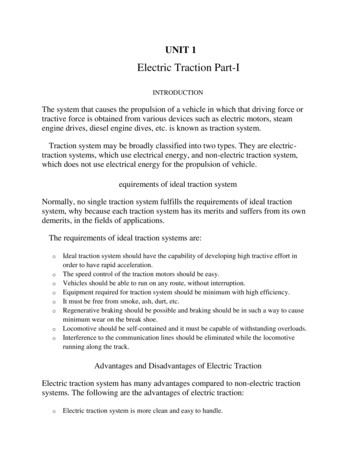
CAMTECH/E/2019-20/EP-05/TM of Train SetDescription22. Motor efficiency at rated power23. Maximum working speed of TM24. Maximum frequency25. Maximum temperature index ofwinding insulation26. Type of suspension11S. No.27. Speed at 160kmph with full wornwheels (877mm dia)28. Type of cooling29. Air entrance temperature30. Protection system31. Class of insulation material32. Terminal box protection degree33. Overall dimensions34. Constructional details viz. Rotor barand rotor end ring arrangement,overhang to terminal box connectionetc.3.2Details95.00%4992 rpm167.5 Hz237 CFully suspended motor with partlysuspended gear drive4992 rpmSelf ventilated, air cooled 50 CIP 20 (machine protected solid objectsgreater than 12 mm)Class 220IP 65 (machine protected againstingress of dust)1431 (L)x1157 (W) x 701 (H)Rotor bar and end ring jointsprotected by use of high strengthalloy shrink ring. All overhangssuitably supported.CONSTRUCTIONAL DETAILS OF TRACTION MOTORTraction motor provided in train set motor coach is a 3-phase asynchronousself-ventilated machine.Fig-14:Train set bogie with traction motor and gearbox assemblyBooklet on Traction Motor & Gear Box of Train SetDecember, 2019
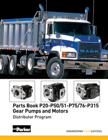
123.2.1CAMTECH/E/2019-20/EP-05/TM of Train Set/1.0Main assemblies of drive complete systemA. Traction MotorB. Gear BoxC. Gear couplingFig-15:3.2.2Main assemblies of traction drive completeStatorThe stator consists of lamination stack, which arefitted in a cast metal housing. The stator windings areshaped copper coils, which are wound from insulatedrectangular profile - banded with additional coilinginsulation and into which slots equipped with a slot liningare inserted.The connections (“circuitry") of the stator coilstake place on the non drive side (NDE). The statorwinding is insulated in accordance with TSA standard andconforms to insulation class 220 in accordance withIEC60349-2.Fig-16: Stator3.2.3RotorThe rotor lamination stack made of layereddynamo sheets is mounted on a solid motor shaft andclamped on both sides by rotor moulding press rings.On the non-drive side (NDE), the lamination stack issecured further with a ring shrunk onto the shaft.Short circuit bars and short circuit rings are weldedon both sides. Shrink collars made up of high-strength,non-magnetic material absorb the loading from thecentrifugal force load on the short circuit rings.Fig-17: RotorDecember, 2019Booklet on Traction Motor & Gear Box of Train Set
CAMTECH/E/2019-20/EP-05/TM of Train Set133.2.4 Motor connectionsTerminal box is located on top of themotor and provided with cable glands.Fig-18:Motor Terminal Box connections3.2.5Traction Motor bearingsThe motor shaft is mounted with ceramic rolling element bearings at both DE(Driving End) & NDE (Non Driving End) in the stator housing. The details are as under. DE (Driving End) : Deep groove ball bearing - 6217 M/HC5C4HS0 NDE (Non Driving End) : Cylinder roller bearing - NU1012 MR/HC5C4Advantages of Ceramic bearing (Hybrid bearing) Bearings balls are made from Ceramic material Bearing insulated at rollers No deformation at higher speed No deformation at higher temperature No wear & tear of the rollersTraction motor bearing lubrication re-greasing detailsFill the grease DE Bearing : 21 gmsNDE Bearing : 9 gmsGrease type : Shell Gadus S3 V2220C 2Fig-19:Removing of used grease from waste grease cover from DE side & fromNDE side (shown by arrow)Booklet on Traction Motor & Gear Box of Train SetDecember, 2019
143.2.6CAMTECH/E/2019-20/EP-05/TM of Train Set/1.0Motor CoolingThe motor is air cooled by a fan mounted at the non-drive end (NDE) of the rotorshaft, air flow is mainly routed through heat exchange channels at the external peripheryof the magnetic stack, one part is ducted inside the rotor, cooling air is filtered at theinlet (grid type).Fig-20: Air outlet/ inlet of traction motor3.2.7Speed sensorFor monitoring the speed, a speed sensor is mounted in the stator housing.Fig-21: Speed sensor location in statorDecember, 2019Booklet on Traction Motor & Gear Box of Train Set
CAMTECH/E/2019-20/EP-05/TM of Train Set3.2.815Pt100 Temperature SensorsFor monitoring the stator temperature, Ptl00 temperature sensor is positioned in thestator housing.Fig-22: Temperature sensor location in stator3.2.9Traction Motor Water Flood Level Traction motor : Water flood level : 400 mm from Rail level Water draining from stator housing in rainy season by opening the drain plug(53)Fig-23: Flood Water drain plug (53)Booklet on Traction Motor & Gear Box of Train SetDecember, 2019
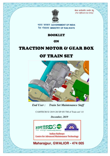
163.3CAMTECH/E/2019-20/EP-05/TM of Train Set/1.0TECHNICAL DATA FOR GEAR BOXS. No.3.4DescriptionDetails1.DesignationPartly suspended gear box assembly2.Type designationGKD 1-52-372A3.Dimensional drawingTSA0165334.Weight of gearbox unit with halfcoupling and without oil m Gearbox490kg5.No. of teeth of Main Gear986.No. of teeth of Pinion197.Gear ratio5.1578.Gear systemSingle stage spur gear9.Center distance between Pinionand Main gear372 mm10.Gear Box : Oil lubrication Type /MakeServo SynGear 75W-90LL / IndianOil MakeCONSTRUCTIONAL DETAILS OF GEAR BOXFig-24: Gear Box AssemblyDecember, 2019Booklet on Traction Motor & Gear Box of Train Set
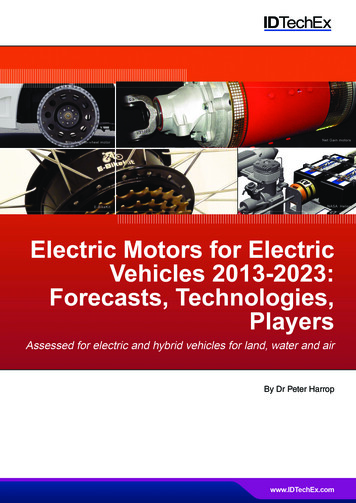
CAMTECH/E/2019-20/EP-05/TM of Train Set17Fig-25:Gear Box Sub-Assemblies1.2.3.4.AxleMain GearPinionFlexible coupling5.6.7.Taper roller bearing – 2 nos.Cylindrical roller bearing – 2 nos.Four Point contact bearing3.4.1 Drive CompletePartly suspended drive with bogie frame fixed motor and axle-mounted gear. Motorshaft and gearbox input shaft are connected by a coupling that transfers torque andcompensates for displacements between motor and gearbox.The main gear is mounted directly onto the wheel set shaft and transfers torquedirectly to the wheel set shaft.Fig-26: Drive CompleteBooklet on Traction Motor & Gear Box of Train SetDecember, 2019
183.4.2CAMTECH/E/2019-20/EP-05/TM of Train Set/1.0Gear Box DescriptionThe gearbox is a helical gear with oil sump splash lubrication.Fig-27: Main Components of Gear Box3.4.3D:Gear box assembled2:Pinion14:Coupling Half gear box side21:Reaction Rod complete610:Main GearW:Wheel set ShaftMotor & Gear half CouplingA curved teeth coupling connects motorwith gearbox. The coupling is torsional rigid, thehalves are self-centering by the teething. Thecoupling consists of two halves whose flangesare bolted together.Fig-28: Motor CouplingDecember, 2019Booklet on Traction Motor & Gear Box of Train Set
CAMTECH/E/2019-20/EP-05/TM of Train Set19The coupling is lubricated by oil and is hermetic sealed to the outside by two steelbellows, so leakage can be suspended. For the regular oil change both coupling halves areequipped with drain plugs, this can be performed on the installed coupling withoutdisassembling from the shafts.The coupling halves are mounted onto the shafts by tapered press fits, includingoil injections for mounting and dismounting.The coupling transfers torque and compensates radial, axial and angular misalignments between motor and gearbox.At the general overhaul the coupling has to be checked visually for checking theability for further use in operation.A slipping bush is installed at the gearbox side to protect the gearbox of too highshock torques that can be generated in the motor in case of a converter short circuit.The coupling is insulated, this ensures that the gearbox bearings are not affected bydischarging currents of the rotor.3.4.4 Connection Gearbox to Wheel SetThe main gear is directly mounted onto the wheel set shaft by a cylindrical shrink fit(the main gear is heated up for the joining operation), including oil injections fordismounting.3.4.5 Gear box HousingThe gearbox housing is casted. The gearbox housing is designed to high stiffness andlow noise radiation and protects oil level indicators from direct hits by rocks from the track.Fig-29: Gear Box Housing3.4.6 Gear box SupportThe gearbox is supported by a reaction rod on the bogie frame. The reaction rodincorporates two spherolastic bushings. During operation, the elastomers will wear andmust be checked regularly and exchanged when the end of the life time is reached.Booklet on Traction Motor & Gear Box of Train SetDecember, 2019
203.4.7CAMTECH/E/2019-20/EP-05/TM of Train Set/1.0BearingsThe input shaft is supported in the gearbox housing by two cylindrical roller bearingsand one four- point contact bearing for the axial forces. These bearings have single piecesolid brass cages.The output shaft is supported by two tapered roller bearings. For the tapered rollerbearings pressed steel cages are used. All bearings are oil lubricated.BearingDataInputmotor sideshaftwheel sidewheel sideReplacementinterval in km30,00,000NU 2217NU 2217bearingECML/C4E-MPA/R120-140Cylindrical rollerNU 2217NU 2217bearingECML/C4E-MPA/R120-140QJ 217QJ 207.0130,00,000Four point ballOutput motor sideTapered rollershaftbearingTapered rollerbearing3.4.8FAG TypeCylindrical rollerbearingwheel sideSKF cation and coolingThe gears are lubricated b
2.2.3 Line & Traction Control Unit (LTCU) 09 3. TRACTION MOTOR AND GEAR DRIVE 10 3.0 TRAIN SET PARAMETERS 10 3.1 TECHNICAL DATA OF TRACTION MOTOR 10 3.2 CONSTRUCTIONAL DETAILS OF TRACTION MOTOR 11 3.2.1 Main assemblies of drive complete 12 3.2.2 Stator 12