Transcription
ZimmerTraction HandbookA Complete Reference Guide to the Basics of Traction
The Traction HandbookAcknowledgments:PrefaceWe would like to acknowledge grateful appreciation to thosewho contributed their time and expertise in the developmentof the ninth editon of The Zimmer Traction Handbook:The principal aim of this book is to present a thorough yet easilyunderstandable explanation of basic traction systems. Throughits numerous illustrations and simplified language, this bookmakes it possible for the trained orderly or orthopaedictechnician to bring to the patient’s bedside all the necessarycomponents for applying several basic types of traction.Moreover, it serves as a source of continuing education,and as a reference for experienced orthopaedic personnel.Thomas Byrne, OPAC, OTCUniversity of CaliforniaSan Diego Medical CenterSan Diego, CaliforniaIt is not the intention of this book to present a detaileddiscussion on nursing care for the traction patient. To do sowithin the confines of this book would risk over-simplificationof the many important physical as well as psychologicalproblems often associated with this type of patient. Moreover,much literature is readily available on such subjects. At the endof this book, a special bibliography listing various nursing carepublications is offered for those seeking additional information,or a more comprehensive understanding of these problems.One important note: as you read through this book, keep inmind that the attending physician combines a highly specializededucation with years of experience and thorough knowledge ofeach patient’s medical history. It is the physician who prescribesall traction setups as well as any changes. His/Her instructionsshould be followed explicitly.Finally, this Traction Handbook is only part of a long-standingZimmer commitment to provide extensive educational programsfor hospital personnel entrusted with the care of orthopaedicpatients. Zimmer also has an extensive educational video serieswhich covers the basics of traction including nursing care. Thisvideo series is available through your Zimmer representative.He or she is available to assist in replacing damaged ormissing parts and to offer helpful suggestions on improvingtraction setups.For additional traction information or literature, contactZimmer Customer Service:2800-348-2759
Table of ContentsGeneral Information on Traction andBalanced Suspension. . . . . . . . . . . . . . . . . . . . . . . . . . . . .Types of Traction . . . . . . . . . . . . . . . . . . . . . . . . . . . . . . . . . . .Application of Traction. . . . . . . . . . . . . . . . . . . . . . . . . . . . . . .Principles of Traction (Nursing Care). . . . . . . . . . . . . . . . . . . .Basic Traction Frame Types . . . . . . . . . . . . . . . . . . . . . . . . . . .Hill-Rom TotalCare Traction Frame . . . . . . . . . . . . . . . . . . .Frame Measurements for BedsNot Listed in this Handbook . . . . . . . . . . . . . . . . . . . . . . .Bryant’s Traction . . . . . . . . . . . . . . . . . . . . . . . . . . . . . . . . . . .Cervical Traction. . . . . . . . . . . . . . . . . . . . . . . . . . . . . . . . . . . .Traction on Humerus-Overhead (90-90). . . . . . . . . . . . . . . . .Pelvic Traction with Pelvic Belt . . . . . . . . . . . . . . . . . . . . . . . .Buck’s Unilateral Leg Traction. . . . . . . . . . . . . . . . . . . . . . . . .Unilateral Leg Traction UsingBöhler-Braun Frame . . . . . . . . . . . . . . . . . . . . . . . . . . . . . .Russell’s Traction. . . . . . . . . . . . . . . . . . . . . . . . . . . . . . . . . . .Split Russell’s Traction . . . . . . . . . . . . . . . . . . . . . . . . . . . . . .Balanced Suspension & Traction withThomas or Brady Leg Splint(Utilizing Skin Traction). . . . . . . . . . . . . . . . . . . . . . . . . . . .Balanced Suspension & Traction withThomas or Brady Leg Splint(Utilizing Skeletal Traction) . . . . . . . . . . . . . . . . . . . . . . . .Patient Exercises. . . . . . . . . . . . . . . . . . . . . . . . . . . . . . . . . . .Applying Skin-Trac Traction Strips . . . . . . . . . . . . . . . . . . . .Universal Brady Balanced Suspension System . . . . . . . . . . .Radiolucent Thomas Leg Splint. . . . . . . . . . . . . . . . . . . . . . . .Assembly Components for RadiolucentThomas Leg Splint . . . . . . . . . . . . . . . . . . . . . . . . . . . . . . .Thomas Leg Splint . . . . . . . . . . . . . . . . . . . . . . . . . . . . . . . . . .Full-Length Sling . . . . . . . . . . . . . . . . . . . . . . . . . . . . . . . . . . .Pearson Attachment . . . . . . . . . . . . . . . . . . . . . . . . . . . . . . . .Foot Support and Heel Rest. . . . . . . . . . . . . . . . . . . . . . . . . . .Böhler-Braun Frame . . . . . . . . . . . . . . . . . . . . . . . . . . . . . . . .DiCosola Rope Holder . . . . . . . . . . . . . . . . . . . . . . . . . . . . . . .Stephan Spreader Bar. . . . . . . . . . . . . . . . . . . . . . . . . . . . . . .Zimmer Spreader Block . . . . . . . . . . . . . . . . . . . . . . . . . . . . . .Zimmer Spreader Bars. . . . . . . . . . . . . . . . . . . . . . . . . . . . . . .4610121418212426283032343638404244505254Zimmer Serrated Clip. . . . . . . . . . . . . . . . . . . . . . . . . . . . . . . .Zim-Clip . . . . . . . . . . . . . . . . . . . . . . . . . . . . . . . . . . . . . . . . . .Mini-Clip . . . . . . . . . . . . . . . . . . . . . . . . . . . . . . . . . . . . . . . . .Zimcode Traction Cord . . . . . . . . . . . . . . . . . . . . . . . . . . . . .Nylon Traction Cord . . . . . . . . . . . . . . . . . . . . . . . . . . . . . . . . .Cast Iron Traction Weights. . . . . . . . . . . . . . . . . . . . . . . . . . . .Weight Carriers For Cast Iron Weights. . . . . . . . . . . . . . . . . . .Sand Weight Bags . . . . . . . . . . . . . . . . . . . . . . . . . . . . . . . . . .Zimcode Traction Weight Bags . . . . . . . . . . . . . . . . . . . . . . . .Skin-Trac Traction Strips . . . . . . . . . . . . . . . . . . . . . . . . . . . . .Flex-Foam Traction Strips . . . . . . . . . . . . . . . . . . . . . . . . . . .Nelson Finger Exerciser . . . . . . . . . . . . . . . . . . . . . . . . . . . . . .Zimcode Footrest . . . . . . . . . . . . . . . . . . . . . . . . . . . . . . . . . . .Zimcode Footrest (with Bed Attachment) . . . . . . . . . . . . . . . .Böhler Steinmann Pin Holder . . . . . . . . . . . . . . . . . . . . . . . . .Kirschner Wire Tractor . . . . . . . . . . . . . . . . . . . . . . . . . . . . . . .Traction Finger Apparatus . . . . . . . . . . . . . . . . . . . . . . . . . . . .Patient Helpers . . . . . . . . . . . . . . . . . . . . . . . . . . . . . . . . . . . .Zimmer Mobile Traction Extra Long. . . . . . . . . . . . . . . . . . . . .Zimmer Mobile Traction Unit-Compact . . . . . . . . . . . . . . . . . .Traction Cart Hook Kit . . . . . . . . . . . . . . . . . . . . . . . . . . . . . . .Zimmer Premium andStandard Orthopaedic Wraps . . . . . . . . . . . . . . . . . . . . . .Traction Softgoods. . . . . . . . . . . . . . . . . . . . . . . . . . . . . . . . . .Zimcode Traction Components . . . . . . . . . . . . . . . . . . . . . . . .Traction Frames for Specific Bed Models . . . . . . . . . . . . . . . .Bibliography . . . . . . . . . . . . . . . . . . . . . . . . . . . . . . . . . . . . . .Traction Component Warranty. . . . . . . . . . . . . . . . . . . . . . . . 29191555656565758585959593
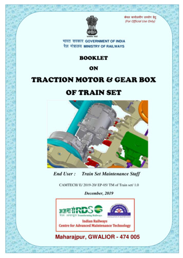
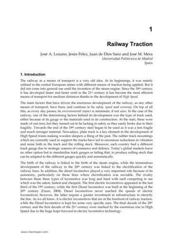
Traction and Balanced SuspensionPurposeAnatomical ConsiderationsThe purpose of any traction setup is one or more ofthe following:1. To prevent or reduce muscle spasm.2. To immobilize a joint or part of the body.3. To reduce a fracture or dislocation.4. To treat joint pathology(s).Traction is the application of a pulling force to a part of the body.But to fully understand this definition, a few basic anatomicalfacts about the human body must be considered.It is important for the nurse/technician to know the patient’sdiagnosis so that an evaluation of the purpose andeffectiveness of the apparatus can be made and, therefore,maintain the traction in such a way that its purpose isaccomplished. To achieve these purposes, the traction setupmust:1. Align the distal fragment to the proximal fragment.2. Remain constant.3. Allow for adequate exercise and diversion.4. Allow for optimum nursing care.Traction and suspension setups are arrangements of bars,pulleys, ropes, and weights which exert a pulling force ona part or parts of the body, or serve to suspend or “float” apart of the body-most frequently a limb. The terms tractionand / or suspension are often confused and, therefore, usedincorrectly or interchangeably. Many traction setups also includesuspension; therefore, it is important for the nurse/technicianto carefully study a particular setup to determine whether it is atraction, a suspension, or a combination of the two.The skeletal system, which supports the body, is composed ofover 200 bones and is held in place by ligaments and muscles.These skeletal muscles act as “movers” of bones. A musclegroup usually originates on one bone and terminates (inserts)on another. Skeletal muscles have a tendon at each end whichattaches like a strip of adhesive tape to the bone. When thebrain signals a muscle to shorten (contract), the tendons ateach end are pulled toward the center (belly) of the muscle. Thisexerts a force on the bones at each end of the muscle, and thebony part with the least resistance moves. Skeletal muscles havetone, which could be described as a state of readiness. Tone iscontinually producing a certain amount of pull on the tendons.Figure 1 illustrates a broken femur. Notice the muscle groupshave pulled the broken parts out of alignment. Proper tractionand suspension will help restore position. The pull of the musclegroup is overcome by a new force (traction) created with weightsand pulleys. Weights provide a constant (isotonic) force; pulleyshelp establish and maintain constant direction. The forces thusapplied must remain constant in amount and direction until thefracture fragments unite.Figure 2 illustrates the same femur after traction has beenapplied to realign (approximate) the broken parts.During an extensive period of healing, the limb must besupported to assist in maintaining fragment alignment, but thepatient should still be able to move about as much as possibleuntil union is achieved. This is why a second system of weightsand pulleys called “balanced suspension” is often used.Balanced suspension permits the limb to “float” over the bed,and facilitates bed pan use and changing of bed linen withminimal disturbance of the fracture.4
With the traction arrangements, countertraction is aconsideration. Countertraction, which is the resistance of thebody to move in the direction of the forces exerted by a tractiondevice, is a factor which is built into each setup by utilizing thepatient’s body weight. When necessary, the countertraction ofthe patient’s body weight may be increased by elevation of thefoot of the bed or using blanket rolls, sand bags, etc.Figure 1Figure 25
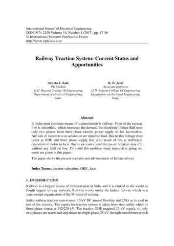
Types of TractionTHREE BASIC TYPES:1. Manual Traction2. Skin Traction3. Skeletal TractionEach has its own special function in the management offractures depending on physician preference, the type offracture and, in some cases, the patient himself.Manual TractionIn manual traction, the hands are used to exert a pulling force onthe bone which is to be realigned. Generally, this type of tractionis reserved only for very stable fractures or dislocations prior tosplinting or immobilization in a cast. It also may be used prior tothe application of skin or skeletal traction or surgical reduction.Skin TractionIn skin traction, strips of tape, mole-skin, or some other type ofcommercial skin traction strips such as Skin-Trac Traction Stripsare applied directly to the skin. Traction boots for leg tractionand pelvic belts for spinal disorders also can be classified underthis category.The prime indication for skin traction is the treatment ofchildren’s fractures and adult fractures or dislocations thatrequire only a moderate amount of pulling force for a relativelyshort period. Certain types of children’s fractures heal in acomparatively short time and do not require extremelyheavy tractive forces to maintain bone alignment. Hence,the child’s skin is more able to tolerate this type of tractionthan the adult’s.6For adults, skin traction is often used as a temporary measureprior to more definitive treatment such as open reduction orskeletal traction. Because of the possibility of severe skinirritation, skin traction should not be used on fractures whichrequire more than 5 to 7lbs. (2.7 to 3.2kg) of longitudinal force.It is also not recommended for continuous traction which isexpected to exceed three to four weeks. Finally, skin tractionis not recommended when controlling limb rotation is ofmajor importance.Skeletal TractionSkeletal traction applies the tractive force directly to the boneusing pins, wires, screws and, in the case of cervical traction,using tongs or halos applied directly to the skull. Skeletaltraction allows the use of up to 20 or 30lbs. (9 or 14kg) of forcefor as long as three to four months, if necessary. Moreover, it notonly exerts a longitudinal pull, but also controls rotation.Skeletal traction is particularly advantageous for unstable orfragmented fractures and those in which muscle forces must beovercome to maintain fracture alignment, e.g., fractures of thefemoral shaft.
Manual TractionSkin TractionSkeletal Traction7
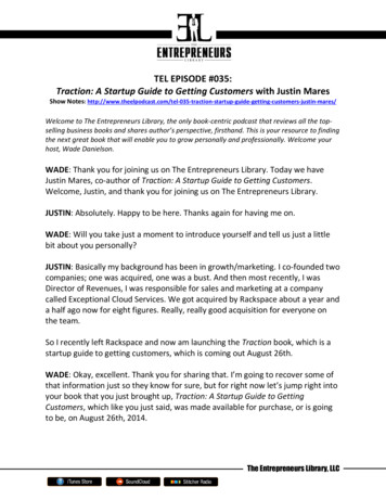
For serious cervical spine fractures or injuries, Crutchfield orVinke cervical tongs are inserted directly into the skull andattached to the traction system. This stabilizes the vertebrae andreduces the chances of spinal cord damage or further injury.For some fractures of the pelvis, a special pelvic tractionscrew is inserted into the ilium and connected to the tractionsystem at the appropriate angle for maintaining fracturealignment.For long bone fractures, skeletal traction requires the useof Steinmann Pins or Kirschner Wires. The basic differencebetween the two is their diameter. Steinmann Pins have a largerdiameter, generally from 5/64in. to 3/I6in. (2.0mm to 4.8mm).Kirschner Wires generally range from .028in. to 0.62in. (.7mm to15mm) in diameter. Both pins also come in a variety of lengthsand point styles. These choices are generally based on physicianpreference, the density of bone through which the pin or wire isto be inserted, and the forces to be applied.Once inserted, the Steinmann Pin or Kirschner Wire isconnected to its respective holder. The holder is thenconnected to the traction force. It must be emphasizedthat Steinmann Pins are not compatible with the KirschnerWire Tractor and vice versa. The Kirschner Wire Tractor andthe Steinmann Pin Holder are designed for use only with theirrespective pins.In addition to the previous classifications, traction also can bedivided into two other categories based on the direction of force.Generally, any loss is negligible, and therefore, for each poundof weight applied, 1 pound of force is delivered.The second of these categories is the block and tackle orsuspension type of traction. This is shown in the Russell’sTraction illustration. In this type of traction the traction systemis attached to the patient in two or more places and also to oneor more other stationary points on the traction frame. Each timethe traction force is attached from the patient to the frame andback to the patient, directional lines of pull, or vectors of force,are being applied.Cervical TongsPelvic Traction ScrewKirschner WiresKirschner Wire TractorSteinmann PinsSteinmann Pin HolderThe first of these, Straight-Line Traction, is best exemplified byBuck’s Traction. Here the traction is affixed to the limb at onepoint and then, using one or more pulleys, is attached to theweight. This causes the force to be applied in only one direction.Any change in the amount of applied force is the result of lossthrough friction caused by bedclothes, turning of pulleys, etc.8
With the vectors of force principle, it is important to rememberthat the actual horizontal pulling force on the extremity is doublethe amount of applied weight.Buck’s TractionFor example, the vectors of force illustration shows two pullingforces (A & B) on the footplate. Each has a pulling force of fivepounds. These two forces combine to produce what is known asthe resultant force (R), or as in this case, 10 pounds. The verticalpull on the knee sling (C) remains at 5 pounds and serves only tosuspend the knee off the bed.A variation to Russell’s Traction is Hamilton-Russell’s Traction.This setup accomplishes the same goal as Russell’s Traction,except it uses skeletal methods.Vectors of Force PrincipleA Steinmann Pin is inserted through the proximal tibia. TwoBöhler Steinmann Pin Holders are then applied as shown in theillustration. One pin holder (with a pulley) applies the tractionforce, while the second holder provides lift to the knee.The traction rope is tied to the vertical pin holder, extended upthrough a pulley on the overhead bar, then through a pulley atthe foot of the bed. The rope is then brought back through thepulley on the second pin holder, through another pulley at thefoot of the bed, and then attached to the weight system.Hamilton-Russell’s TractionAs with regular Russell’s Traction, the vectors of force principleis applied. The horizontal traction force is twice the amount ofweight applied, while the lift is equal to the actual weight.Russell’s Traction (Suspension Type)9
Applications of TractionGENERAL TIPS AND PRECAUTIONSBefore you begin applying traction, remember:1. Skin traction cannot be applied over an open wound.2. Skin traction may be contraindicated in patients withabrasions, lacerations or superficial infections in theimmediate area. This also includes patients with varicose veinsor circulatory disturbances. It also may be unsafe for diabeticsor patients with very thin skin. When possible, be sure therehas been a thorough admission history taken on the patient.This is especially important in cases where the doctor has notyet had the opportunity to do a complete examination.3. Check with patient for possible adhesive allergies.4. Do not reuse traction cord. It does become worn and mayeventually break. It also can become contaminated by bacteria.After the above procedures have been completed:1. Before threading traction cord, lubricate all pulleys withsilicone spray or a small amount of mineral oil.CAUTION: Never lubricate pulleys when traction is completely setup unless the attending physician is present to readjustthe amount of weight. Lubrication changes the frictionwhich in turn, alters the balancing forces.2. To help prevent pressure sores, a concentrated effort should bedirected at avoiding pressure in the following locations:Upper Extremitiesa. Bony prominences about the elbow.b. Anterior soft tissues of the elbow joint.c. Bony prominences about the wrist.d. Volar (palm side) surface at the wrist.10Lower Extremitiesa. Peroneal nerves at the neck of the fibula.b. Hamstring tendons at the back of the knee.c. Bony prominences about the ankle.d. Back of the heels.e. Soft tissues at the front of the ankle and topof the foot.f. Greater trochanters (outer area of upper thighs).Trunka. Prominences of the spine.b. Borders of the scapulae (shoulder blades).c. Crest of the ilium (upper edges of pelvic blades).d. Sacral areas (tail bone).Pressure on the elbow joints, wrists, knees, and heels maybe minimized by a generous wrapping of wide sheet waddingin order to distribute the weight of a limb over a wide area.Elevation of the ankle may be necessary to lift the tip of theheel away from the bed. Preventing a pressure sore is easierthan curing one.3. Weightsa. Never add or remove weights without specific orders fromthe attending physician.b. Never allow weights to touch the floor, drag on bed partsor touch other weight systems. These conditions can reducethe applied force and cause the traction apparatus not toperform as intended. Keep all weights hanging free.c. Do not allow traction weights to hang over any part of thepatient. Traction cord does occasionally slip or break so itis important not to allow the traction weight to strike andinjure the patient. If necessary, on some older types ofapparatus, add an extra bar and pulley to get the weightin a free hanging position away from the patient.
d. Although the photos in this handbook show the tractionweights off the foot of the bed, some hospitals andphysicians may require them to come off at the head of thebed. Both methods are acceptable, however, the reasoningbehind each differs.From Foot End:a. Weights are out of patient’s reach.b. They are readily visible for inspection.c. With shock blocks under the head of the bed, weightshang freely with less equipment.6. If the patient must be moved while in traction, the attendingphysician or authorized healthcare provider who set upthe traction must be present. Failure to readjust traction tothe same precise configuration after transport can result inmisalignment with serious consequences.7. All traction equipment must be cleaned with some type of aliquid sterilizing solution (ex. 10% bleach solution etc.) aftereach patient use.From Head of Bed:a. Weights are away from visitor’s reach.b. They are less subject to bumping by attending personnel.c. Less equipment is required if shock blocks are under footof bed.4. Never apply pillows, sandbags, ice bags, hot water bottles,surgical dressings, cotton, sponge rubber, towels, felt, or anyother type of pad to a patient in traction unless specificallyordered by the attending physician.5. A routine should be established and followed to check eachtraction setup in detail. In addition, all nursing personnelcoming into the patient’s room should, out of habit, makea quick visual inspection of the equipment. This inspectionshould begin with the weights and follow along each rope tothe patient to be sure that:a. Weights are hanging free.b. Ropes are in the pulleys, foot-plates and spreader blocks.c. Knots are free from pulleys.d. Bed linens, etc., are not interfering with the traction forces.11
Principles of TractionRELATIONSHIP TO NURSING CAREA great deal of the nursing care (and a good deal of equipmentmaintenance) related to the patient in any traction applicationis based upon certain fundamental principles. It is, therefore,imperative that the nurse/technician be constantly alert for thefollowing:1. POSITIONThe patient should be in the supine position (on his/her back).Proper position includes keeping the entire body in goodalignment. Also, either a solid bottom bed or bed boards mustbe used for all orthopaedic patients.2. COUNTERTRACTIONFor any traction to be effective, there must be countertraction.If the force of pull of the traction is greater than thecountertraction supplied by the body weight, the patient willslide towards the traction force, or his traction splint mayimpinge on the traction pulley. Should this happen, additionalcountertraction may be obtained by tilting the bed away fromthe traction force. Traction and countertraction representforces in balance; for this reason the patientshould not have his back raised more than 20 degrees,or be allowed to sit up.3. FRICTIONAny type of friction will reduce the efficiency of traction andhinder the pull. Implications for nursing care include checkingto see that:a. The spreader or footplate is not touching the end of thebed.b. The weights are positioned at a reasonable level from thefloor; a considerable distance below the pulley; hangingfree of the bed; and away from the patient.c. All knots are clear of the pulleys.d. There is no impingement on the traction cord from bedclothes or any other apparatus.12e. The patient’s heels are not digging into the mattress.If any of these conditions are not being met, immediatecorrective action is indicated.4. CONTINUOUSIn general, for traction to be effective, it should be continuous.NEVER remove it without a doctor’s order. Furthermore, checkfrequently to make sure tapes are not slipping, that pulleysare working properly and that the components of the tractionapparatus are correctly and tightly assembled.5. LINE OF PULLOnce established correctly, the line of pull should bemaintained.6. PROTECTION OF THE CARDIOVASCULAR SYSTEMImmobilized patients are at risk for venous thrombosisand/or pulmonary embolus. The nursing goals are to monitororthostatic tolerance and prevent venous stasis. Interventionsto prevent venous stasis include:a. Instructing the patient in hourly ankle rotation, flexionand extension exercises.b. Avoiding or minimizing positioning that causes externalpressure on venous walls such as knee gatching orcrossing legs.c. Using, on physician order, anti-embolism stockings orpneumatic sleeves.7. MAINTENANCE OF NEUROVASCULAR STATUSNeurovascular compromise may be avoided by using thefollowing interventions: regularly assessing neurovascularstatus with particular attention to traction apparatus andpressure areas; changing the patient’s position within thelimitations of the traction every two to four hours; reportingany signs and symptoms of neurovascular compromise to theattending physician.
8. SKIN CAREStatic positioning in traction can cause pressure that impairscapillary flow to the skin, resulting in tissue necrosis andpressure sores. Skin integrity can be maintained by:a. Assessing skin integrity over bony prominences and anyareas of the body which are covered by or attached totraction apparatus.b. Massaging potential pressure areas every two tofour hours.c. Using pressure relief devices or pressure relief beds.If skin breakdown occurs, massage should bediscontinued to prevent further tissue damage. Theadhesive straps used in skin traction heighten the risksto the skin and should be selected, applied, andmonitored very carefully.9. MAINTENANCE OF THE MUSCULOSKELETAL SYSTEMImmobility decreases muscle strength, impairs skeletalstrength, and limits joint mobility. These problems can beminimized by:a. Having the patient perform regular isometric and/orisotonic exercises of uninvolved extremities and theinvolved extremities as prescribed by a physician.b. Periodically positioning the patient in the fullyextended position.c. Allowing the patient to perform as many daily activitiesas possible.If the patient will use crutches after the traction isdiscontinued, he/she should strengthen his/herquadriceps by:a. Pulling his/her toes toward his/her nose while pushinghis/her knee into the bed.b. Sitting up in bed and pushing his/her palms againstthe bed to raise his/her buttocks off the bed.Directions for setting up the upper and lower extremityexercises appear on page 44-47.UpandOverDownandOverUpandThroughHOW TO TIE A TRACTION KNOTTo save time, follow this simple phrase: up and over,down and over, up and through. Practice a few times witha traction cord and this illustration.Once you have tied the traction cord, allow about 4in.(10cm) at the end. This extra length of cord allows you toadjust the knot later without replacing the cord. Secureall knot ends tightly with adhesive tape.10.NEVER IGNORE A PATIENT’S COMPLAINTThis rule should be followed above everything else.Check it out.11. TRACTION SYSTEMS CAN VARYWhile it is essential for those caring for traction patientsto know the correct application of traction, the nurse incharge must remember that doctors may vary theirtraction methods for specific reasons. The nurse should,therefore, inform all floor personnel concerning anymodifications to a particular traction setup institutedby a physician.Sometimes it may be helpful to take a photo of the setup.This will show nursing personnel on all shifts how thetraction setup should be maintained.13
Basic Traction Frame TypesEvery traction system begins with a basic traction frame.Essentially, the basic frame is the foundation around whichthe complete system is built. For a listing of traction framesfor specific bed models, see page 82.Zimcode Buck’s ExtensionFor cervical and pelvic traction. Adjusts vertically and horizontally. Components color coded to simplify setup. Vinyl coated arms protect bed.Prod. No.ComponentsDimensionsQty.00-0619-000-00Complete System00-0640-006-00Single Clamp Bar27in. (69cm)100-0619-001-00Swivel Clamp Bar w/Pulley9in. (23cm)100-0619-002-00Double Pulley Bar18in. (46cm)100-0619-003-00Panel Clamp-Buck’s1Child’s Crib Used for fractures of the femur in children under two yearsold or weighing less than 30lbs. (14kg). Provides stabilization of the hip joint where use of cast isnot indicated. Bilateral traction helps prevent rotation and facilitatesstabilization of the patient.14Prod. No.ComponentsDimensionsQty.00-0640-002-00Swivel Clamp Bar66in. (168cm)100-0640-013-00Panel Clamp-Upper100-0640-014-00Panel Clamp-Lower100-0640-011-00Center Clamp Bar36in. (91cm)200-0640-004-00Single Clamp Bar9in. (23cm)100-0640-006-00Single Clamp Bar27in. (69cm)100-0640-008-00Pulley4
Straight FrameBasic frame setup for beds with I.V. Sockets. See page 82 oncomponents for individual bed models.Single frame will hold a patient weight of up to 250lbs.(113.4kg) as long as the Curved Double Clamp Bar(00-0640-021-00) is utilized. Without the Curved DoubleClamp Bar, the weight limit is 200lbs.Offset FrameBasic frame setup with an additional feature of an offset uprightbar at the head to allow clearance for a wall light fixture. Seepage 84 on components for individual bed models.Single frame will hold a patient weight of up to 250lbs.(113.4kg) as long as the Curved Double Clamp Bar(00-0640-021-00) is utilized. Without the Curved DoubleClamp Bar, the weight limit is 200lbs.15
Four-Poster (Balkan) FrameDesigned for special traction setups and also to accommodateincreased weight bearing by patients weighing between 250 and450lbs. (113-204kg) as long as the Curved Double Clamp Bar(00-0640
The Traction Handbook Acknowledgments: We would like to acknowledge grateful appreciation to those . San Diego Medical Center San Diego, California Preface The principal aim of this book is to present a thorough yet easily understandable explanation of basic traction systems. Through its numerous illustrations and simplified language, this book