Transcription
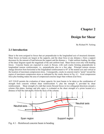
Shear in Steel Beam-to-Column ConnectionsThe current AISC design formula is shown to be conservativeby theoretical analysis and tests of a full size beam-to-columnconnection subjected to moment, shear and high axial loadsBYD. J. F I E L D I N GA N D J. S.ABSTRACT.—The condition of high shearstress in rigid frame connections and theeffect of high axial force is investigated.A yield condition is derived and verifiedby a test. After yielding in the test specimen, stable joint deformation was observed under monotonic loading and theconnection carried 2.75 times what isconsidered to be the yield strength inshear. The current AISC design formulais shown to be conservative.IntroductionIt is frequent practice in structuralframe analysis to consider that theconnections are the intersections ofbeam and column centerlines and thatthese junctions a r e rigid. According tothis assumption there is no relativechange in angle of rotation between abeam centerline and a column centerline. Actually a real connection shouldbe considered as a structural m e m b e rwith finite dimensions and loading.Figure 1 shows an interior structuralconnection with an antisymmetricalloading as would be caused by wind orearthquake. The axial forces in theb e a m s a r e usually negligible. A similarloading occurs on an exterior connec-IiprHUANGtion under wind or gravity types ofloading. If the m o m e n t M in Fig. 2 isreplaced by the forces T whereMand db is the beam depth, then the highcolumn-web shear force becomes a p parent. T h e design of the connectionshear stiffeners is based o n this largeshear force 1 2 by limiting the shearstress r to the value ajs/laccording tothe Von Mises yield criterion. This isusually written asI(2)Awwhere A„. is the area of the column webin the connection. If n o shear stiffeningis present in the column web thenAw dcw(3)in which dr is the column d e p t h and wis the thickness of the web in the connection. If shear stiffening is present,an effective web area should be used.C o m b i n i n g eqs (1), (2), and (3) givesthe 1969 AISC design formula from theC o m m e n t a r y of the Specification, Sections 1.5.1.2 and 2.5awV3M- 7l Ax / 3 (MTMlw — I - oy dr \ dhdb\Va I (5)jThis formula dictates shear stiffeningfor a connection based on a m o r erealistic value of shear force but independently of the column loading Pain Fig. 1. If Pa is at the ultimate columnload, eqs (4) a n d (5) still imply the samecolumn web shear capacity as if Pawere not present. This inconsistencyalong with observed column web sheardeformation in a frame test 3 p r o m p t e dthe current study of the effect of axialload on connection design.In 1966 a series of seven pilot testswas begun on simulated exterior connections. T w o of the seven tests weredesigned so that the column web withinthe connection would yield in shear;however, in all seven tests, failure(4)o-v db drM0 1 ZTVavrI)- Mr" T bp(1)db1, the design formula can be generalizedto include the additional shear forcefrom Mi for an interior connection andthe reduction in shear force due to thecolumn shear V„ to give 2bf—Fig. 1—Interior beam-to-column connectionActually db and dc should be distancesbetween flange centroids. If this formulais used the column web within the connection will be prevented from yieldingunder the action of the beam m o m e n tM in Fig. 2. However, referring to Fig.MXD. J. FIELDING and J. S. HUANG arewith the Fritz Engineering Laboratory.Dept. of Civil Engineering, Lehigh University, Bethlehem. Pa.The work described in this paper wascarried out as part of an investigationsponsored jointly by the American Ironand Steel Institute and the Welding Research Council—publication of the paperwas sponsored by the Structural SteelCommittee of the Welding Research Council.WELDING4Fig. 2—Exterior beam-to-column connectionRESEARCHSUPPLEMENT 313-s
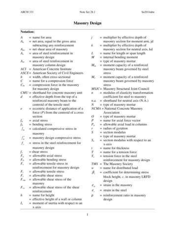
loaded as indicated in Fig. 1 in whichthere is a high moment gradient orshear within the connection. In Fig. 3is shown an assemblage of a column andcantilever beam. The elastic columnmoment and shear diagrams are alsoindicated. The portion of the momentdiagram within the connection is notactually known but can be assumed as alinear transition indicated by the dashedline. This assumption gives rise to theshear diagram in Fig. 3 indicatinguniform shear throughout the columnweb. This is equivalent to saying thatthe beam moment Mr enters the connection as shear at the beam flange asindicated in Fig. 2. This is reasonablebecause most of the beam moment iscarried in the flanges for wide-flangeshapes.Two points are important in thisargument. First, the assumed forcecouple is statically equivalent to thereal moment and, therefore, equilibrium is maintained at the connection.Second, the complexity of an exactsolution of the stress distribution withinthe connection coupled with pastobservations of the pattern and effectof yielding warrants a simplified appioach.It is often implied that this connection shear force is carried by thecolumn web as a uniform shear stressas in eq (2). Although an elastic solution5 using an Airy stress function showsoccurred by the formation of plastichinges outside the connection and atloads very much in excess of the predicted failure loads4. In the study it wasconcluded that connection shear deformations were larger for higher axialload. At that point it was obvious thatthe shear capacity of an unstilfenedconnection should be based on anallowable story drift limit and not onsome imaginary ultimate load expressedby bound solutions using plasticitylimit theorems.4 A study of the elasticbehavior of connections has beendone,5 and a study of the inelastic behavior is underway at Lehigh University.The test of a beam and column assemblage reported herein is part of thelatter investigation. The objective of thetest was to study the influence of axialforce on the behavior of beam-tocolumn connections that must alsocarry high shear from beam moment.In order to attain the test objectives,requirements placed on the assemblagewere:1. That the connection be very lowin shear resistance.2. That the column web within theconnection carry large axial force inaddition to high shear force.Theoretical AnalysisAssumptionsA beam-to-column connection can beCOLUMNMOMENTSTRUCTUREdr -2tfCOLUMNSHEAR(At V r 86kips) 70(6)I — *p— rM.- M.r UUJ. -,Ml!that the distribution is a parabolicvariation from a constant stress at theedges, the error in assuming a uniformdistribution is small. This is the sameapproximation that is made concerningthe shear stress distribution in beamwebs. In addition, the experimentalresults reported by Naka et al7 showthat the elastic shear stress distributioncomputed from strain gage data ismore nearly uniform than parabolic.Therefore, the assumption of uniformshear stress in the connection panel ismade.In order to evaluate the behavior ofthe connection some reference loadsmust be calculated. Considering thestructure in Fig. 3 there are fourpossible failure modes. First, Mr canreach the plastic moment for the beambefore the column fails. Second, theplastic moment for the column can bereached at sufficient locations to causea column mechanism. For the fixed-endcolumn in Fig. 3 three plastic hinges arerequired; 6 M„, Mh, and ML will reachthe plastic moment first. A third failuremode could occur if the column webis thin, that is, shear buckling of theweb. Normally the column web dimensions are such as to preclude shearbuckling. If the column depth dc, flangethickness t/, and web thickness w(including doubler plate thickness) satisfy the ratio\h2\ ,M MQ (MrIih2 \WMbLm1\ -" "V \1VarM o \.\MbConnectionShear QM1, 2 JaMrM VrLvb/M /abifWE 1\bt—bML\V0M -ILtaP VrLegend: TheoryMeasurediScale:I . I . I0kip-ft.Fig. 3—Column moment and shear diagrams314-s : J U L Y1971P200iFig. 4—Connection stress statesMbV /
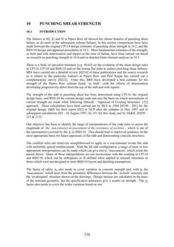
shear buckling will not be a problem.'The fourth failure mode is that ofgeneral yielding in the column web dueto the high shear force that is present.This mode of failure is stable in nature—that is, there is no unloading. Although the web of a wide-flange beamis yielded due to shear, the beam willcontinue to carry additional load untilshear deformation becomes excessive.2This same behavior was observed inthe test of a corner connection 8 inwhich the stiffness decreased substantially but with no instability. Thisfourth failure mode is the object ofthis study and, in the following analysis,is assumed to be critical.Von Mises Yield Criterionmately constant. This means that eq(7) can be solved for any single convenient point in the connection panelrather than at every point and that theconnection panel yields throughout ata unique loading.At the center of the connection inFig. 4, ab can be taken as zero and r„can be taken asPwhere Ac is the column area and P„ o-uAr is the yield load of the column.From previous discussion2 the shearstress is written:TabThe Von Mises yield criterion or themaximum distortion energy theory offailure9 for biaxial stress state as existsin a joint panel is written:cr,,2 — aa(Tb o b'2 3r„6 2 a,,-Aw ?-')(9)ve tdcSubstituting eq (8) into eq (7) gives:(0 (7)where a and b refer to the coordinateaxes in Fig. 4. In one test,4 strain gageswere applied on the column web withinthe connection and the principal stresses were calculated and recorded. Fromthese data for a connection with noadded shear stiffening it can be seen thatthe left hand side of eq (7) is approxi-(8)) "Arvalue. Unlike eqs (4) and (5) currentlyused in design'-2 and which ignoreaxial force, eq (10) indicates that r„ftmust be zero when P Py (columnfully yielded by axial load).The equations derived can be used topredict general yielding of a connection.Although such information is inadequate to predict ultimate capacity, itis useful in predicting the point at whichinelastic action begins. This will bediscussed again in light of experimentalresults.Equations 9 and 10 can be combinedto give an interaction equation similartoeq (5):23r„(,(10)This equation can be solved forTab Ty, a reduced yield stress in shear.When T„b in eq (9) is equal to r„' theentire column web will yield due tocombined axial load and shear. Equating the right hand side of eq (9) to r,/,any of the interrelated moments andshear can be calculated as a limitingMi ' )(0ODThis formula specifies the columnweb thickness required to preventgeneral yielding under the action ofantisymmetrical beam moments Mrand Mi and column load P.Conversely, eq (11) can be used tocompute the moment Mr that will causeyielding of a column web with thicknessw. All the moments and shears in eq(11) are related by the equations ofstatic equilibrium.Column Top Plate2"x24"x30"— J C - U4 (Same at Other End)'/4(a)h-15'21*"A yZ( Bending Neglected)(b)7 ? 7 7 ? J / / / .ARigid LinkTT//iiiH7//-—QfrA'A(c)Column Bose Plate3"x24"x24" 7 rrFig. 5—Connection loading and equivalent cantileverFig. 6—Connection assemblage—BIWELDINGRESEARCHSUPPLEMENTI 315-s
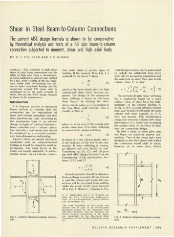
Elastic Connection BehaviorThe shear force in the connection ofFig. 5(a) is:Q T - V(12)QAw(13)and, from r Gy, the elastic sheardeformation of the column web withinthe connection can be computed as:(14)GAU.The bending deformation within theconnection has been neglected but canbe included as others did.8 The sheardeformation y from eq (14), measuredin radians, will be the relative anglechange from the right angle betweenthe beam and column centerlines. Thisdeformation is normally neglected inframe analysis. The angle y is not astrain at a point but rather the grossaverage panel shear deformation.It is apparent that the connection inFig. 5(a) can be represented by thecantilever in Fig. 5(b) whose length isone-half the beam depth. Equations(13) and (14) are the same for thecantilever and the connection. Thelimit of elastic behavior will be atT Ty when there is general yieldingof the web in shear. At this point:Qv T„'AW(15)and(16)Post-Yield BehaviorThe preceeding equations predictgeneral yielding of a connection panel.It is not necessarily true that the columnflanges bounding the joint are alsoyielded. If they are elastic there will besome remaining elastic stiffness of theconnection until these flanges too arefully yielded by the monotonic loading.This elastic stiffness can be computedfrom the model in Fig. 5(c) in whichthe flanges, connected by a rigid link,bend independently of the web.CV33 E(2If)shear strain,. When the connection is7elastic,The shear stress r is7Of particular importance in computing connection deformation is thestiffness, or the ratio of shear force to11(17)where Q/ is the portion of Q carriedby the flanges and // is the moment ofinertia of each flange (bf X ?/).— GA„.(19)7This is obtained from eq (14) assuming that the flange contribution Qsis negligible. When the column webyields, the elastic shear modulus Gwill become zero as evidenced by tests.10However, the flange contribution fromeq (17) gives:Qf724 Elydb2(20)where I has been taken as half the beamdepth dh.The stiffness of the connection for aninelastic web is still based on the elasticmodulus and section dimensions aslong as the flanges have not fully yielded.This appears to be reasonable if oneconsiders the large shear strains thatare required before the connection panelcan strain harden. It is not implied thatstrain-hardening does not occur locallybut that the shear stiffness immediatelyafter yielding of the column web isprovided by the remaining elasticmaterial in the column flanges. Atlarger strains eq (20) will not be reliableas the flanges too become yielded.However, at larger strains it is possiblefor the entire connection web to strainharden. This strain-hardening effect hasnot been included in this analysis norhas the limit of flange contribution in theinelastic range.The limiting shear for this behaviormust theoretically correspond to theformation of a plastic mechanism.2However, tests have indicated increasedcapacity due to the occurrence of strainhardening in regions of moment gradient.11Description of TestThe single test described in thissection was proposed to study thebehavior of steel frame connectionsunder antisymmetrical moment loadingand axial loading.12 Pilot tests4 indicatedthat axial load has some effect onyielding and deformation of connections and so special emphasis wasplaced on these factors.Design of Assemblage'/-f-2W(18)For this model, the interaction between the web and flanges after yieldinghas been neglected since it is assumedthat the web will deform freely. Thismodel is used only after the connectionDanel is yielded.316-sJU LY1971The assemblage shown in Fig. 6,designated BI, represents an exteriorcolumn and the left hand portion of abeam from a multistory frame. Theparticular beam and column sectionswere chosen with two objectives in mind.First, the loads that cause failure withinthe connection web panel were to bemuch lower than the loads to causefailure of the column or beam outsidethe connection. A beam section with alarge plastic modulus was required;however, this plastic modulus had to berealized in the thickness of the flangesrather than in the depth of the beam. Anincrease of the beam depth would increase the strength of the connectionregion proportionally, so that the dangerof a failure outside the connection is notdiminished. Therefore, of beams withequal depths, only those with thegreatest thickness of the flanges hadbeen considered. Unless the beams andcolumns were designed in this way, ashear failure within the connectionwould not occur. Further, by omittingthe required shear stiffening, the objective of obtaining a connection shearfailure should be realized.A second consideration was that thecolumn and beam sections should forma connection of a realistic size andshape—that is, the beam depth shouldbe greater than the column depth andthe plastic moment of the beam shouldbe approximately twice that of thecolumn.Interaction curves for combinationsof sections were used to finally select anassemblage consisting of a W14 x 184column and a W24 X 160 beam ofASTM-A36 steel.13 The interactioncurves for the assemblage are shown inFig. 7. This is a plot of the non-dimensional column force ratio P/P„ and thecolumn moment M,. defined in Fig. 3and non-dimensionalized by the fullplastic moment of the column. Thesecurves are dependent upon geometryand boundary conditions. The assumption was made that the column endswould be fixed against rotation. Thebeam section failure curve representsthe value of M„ when a plastic hingewould form at the end of the beam. Thecolumn failure curve shown is Formula(2.4—3) of the AISC specification1 forcolumns bent in double curvature. Theother three interaction curves refer togeneral yielding of the connection usingeq (4), (5), and (11) and equations ofstatics to relate beam moment tocolumn moment M„. At high axial loadthe interaction curves for the connection and the column outside the connection are very close. Obviously, themargin between connection yield fromeq (11) and member failure outside thejoint is a maximum when P/P,, 0.5.The geometry of the specimens of theprevious test series4, called the A-series,was adopted in this test as shown inFig. 6. That geometry was satisfactoryexcept for the following points:1. Local buckling occurred in boththe beams and the columns.2. The length of the column was tooshort. As a result, the shear force in thecolumn was high and cancelled out a
- Stiffener Both Sides4 V 4 "x5"xl2*8"MQ.»-, * - .-»-*-rj(T») Mh 5—* Section b-bTTayPi /87 rection PlateVx3"x20" JV9""1\ Dia. ErectionBolts V Holes Ve2S\v /; lr ;/ \-Backing StripVxVxWfc"(Typ.)0.5Beam SectionFailureScale:5in.Section o-oFig. 7 — I n t e r a c t i o n curves for t h e assemblage c o n s i s t i n g ofW14X184 (column) and W24X160 (beam)large part of the shear force in the connection.These two factors caused failures inthe A-series specimens outside the connection. The AISC design formulas1have been used to check for localbuckling in this test. It was expectedthat the shear force in the columnwould be reduced sufficiently by takinga length of the column between inflection points of ten feet.The length of the beam in Fig. 6 wasdetermined by the capacity and strokeof the available hydraulic jacks, theavailable testing space, and the allowable difference between the axial loadsin the top and bottom parts of thecolumn. As shown in Fig. 3, the axialload in the bottom part of the columnwas P Vr where Vr was the beamload. The objective here was to keepP Vr approximately equal to P toavoid premature column failure due toexcessive reduction of Mpr at thesection below the connection.The details of the connection between the beam and column and thestiffening are shown in Fig. 8. Althoughthe fabrication was completely done inthe shop, the details are those of awelded field connection. An erectionplate was fillet welded to the columnflange. This plate had holes for erectionbolts and was to be used as the backingstrip for the beam web groove weld.The beam flange to column flange10Fig. 8—Connection panel d e t a i l swelds were single bevel groove weldswith 34 in. root opening.The horizontal stiffeners on the column web were designed according tothe AISC specification1 to resist thecolumn web crippling force from thebeam flange. The »{n in. fillet weldsconnecting the stiffeners to the columnflanges were the minimum allowed bythe thickness of the parts joined. 1 However, these welds tore during the test(see Appendix) and were built up to Yiin. fillet welds for completion of thetest.Section a-a in Fig. 8 shows that thestiffener was narrower than the beamflange width. There are no design guidesconcerning this detail, and the widthof stiffener was governed by the limitingwidth-thickness ratio. 1Test SetupA special arrangement was devised toapply loads to the assemblage of Fig. 6.This setup is shown in Fig. 9. The axialload in the column was applied by a5,000,000 lb capacity hydraulic universal testing machine. The crossheadof the testing machine through whichthe applied column load was measuredis indicated. The base of the assemblage was bolted to the floor with four\y2 in. bolts.The beam load was applied throughthree 100,000 lb capacity hydraulicjacks in tension as shown in Fig. 10.WELDINGThese jacks were arranged in a planeperpendicular to the plane of the assemblage, the center jack being vertical andthe outside jacks being slanted awayfrom the beam toward the floor. Thisloading scheme provided stabilityagainst lateral-torsional buckling of thecantilever beam.The column ends were made flatended. This provided greater stiffnessto the assemblage so that jack strokewould be conserved; however, thestructure was more indeterminate as aresult. The observed column end rotations are indicated in Fig. 11. Thebending moment Mv in Fig. 3 couldbe applied to the testing machine crosshead with no distress to the system;however, the upper column shear V„would cause the crosshead to drag onits guide rails. This condition waseliminated by providing a W36 X 194beam to accept the column shear (seeFig. 9). The beam was connected to thecolumn top plate through thirty 1J4in. A325 high-strength bolts, and restedon its side, supported by two smallermembers. The smaller members werebolted to the testing machine columns,and the stiff beam reactions weredelivered to the sides of the testingmachine through special bearing padsof mild steel. No lateral bracing wasprovided for the column.In many respects this investigationwas a pilot test to determine the feasibility of testing such assemblages underRESEARCHSUPPLEMENT 317-S
- 5,000,000 lbTesting MochmColumnLegend:Testing MochineCrossheodDynamometersFig. 9—Test setup23B (RADIANS)46x10"Fig. 11—Column end rotationsFig. 10—Beam load applied by threehydraulic jacksantisymmetrical loading condition. Thesetup was designed for reuse and hasthe following limiting conditions:1. Maximum column load: 5,000,000lb (Load tested to 819,000 lb)2. Maximum beam load: 270,000 lb(Load tested to 216,000 lb)3. Maximum stroke at end of beam:11 iv in. (Tested to 11 7, in.)4. Maximum column dimensions:15% in. X 15% in. (Limitation is dueto floor bolt hole pattern.)InstrumentationStrain gages and dial deflection gageswere used to check forces and displacements. Four strain gages werelocated at each of four column crosssections as indicated in Fig. 12 Sectiona-a. These gages provided sufficientinformation to enable computation ofthe resultant axial force, bending moment, and shear in the column aboveand below the connection. The beamload was monitored by two strain318-s J U L Y197 1gages on the beam web, Section b-b.Stiffener strains were measured usingfour gages on each stiffener and onegage on the beam flange just outside theconnection and directly in line with thestiffener gages. These strain gage locations are indicated in Fig. 12 Sectionc-c. Strains were automatically read andrecorded.Dial gages were employed to measureover-all column shortening, beam deflection, and lateral movement of thecolumn midpoint. The arrangement ofeight dial gages in the panel zone isshown in Fig. 13. This pattern wasduplicated on the opposite side of thespecimen so that measurements couldbe averaged, thereby excluding out ofplane behavior.Each dial gage was mounted on a postwhich in turn was tack welded normalto the column web. A wire was thenstretched between the dial gage postand another post. The gage length, thedistance between the two posts beforestraining, was recorded prior to thetest. Two of the dial gages were used tomeasuie diagonal deformation of thepanel zone, one gage being mountedalong each of the tension and compression diagonals. The other six gages wereused to measure relative movementbetween the sections indicated in Fig. 12.Translation and rotation was measured between sections c-c and d-d, d-dand e-e, and f-f and g-g. Sections d-dand f-f are the centerlines of the connection. Sections c-c and e-e were located1 in. outside the connection boundaries.Section g-g was 4 in. away from thecolumn flange.The absolute rotations of both thetop and bottom end plates of thecolumn and of the support end of thebeam were measured with level barsattached to the member webs directlyinside the flanges. The locations of thelevel bars are indicated in Fig. 12.The column load was applied andmeasured through the hydraulic universal testing machine. The beam loadwas measured using three dynamometers located in series with thehydraulic jacks in Fig. 10. The dynamometers were each calibrated before thetest.Before testing, the assemblage waswhitewashed so that yielding patternscould be observed and photographed.Mechanical PropertiesOver-all dimensions of the assemblage as well as cross-sectional dimensions of the beam and column weremeasured. The over-all dimensionsagreed with those in Fig. 6 to withinHi 6 in- s 3 those dimensions are nottabulated. The measured cross-sectionaldimensions of the beam and columnsections are given in Table 1 along withthe corresponding dimensions from theAISC Manual. 1Tensile tests were performed onspecimens taken from the beam andcolumn flanges and webs. Two specimens were cut from the flanges and twofrom the webs of each section. The testresults in Table 2 are the static yieldstress, the tensile strength, and thepercent elongation in 8 in. Test resultsreported for the web are the averageof two tests. The static yield stress is
4-6Fig. 13—Panel zone deformation measured by dial gages (V 117 kips)l——r(8"18"i — ,,;iSection b-bTest Results And DiscussionLegend:Column Shortening— SR-4 Strain Gages — Lever Bors for RotationMeasurementFig. 12—Instrumentationdetermined by reducing the testingspeed to zero in the plastic region of thestress-strain relationship14. This procedure eliminates the effect of strainrate in the plastic region.The mechanical properties from themill report for the W14 X 184 aregiven on the bottom line of Table 2. Thenotable difference in yield strength ismore than one might expect as a resultof the difference in testing speed.The yield stress from the web testswas used to compute Vi, V2, and V,/.Py was calculated as the sum of theproducts of web area and web yieldstress and flange area and flange yieldstress.Test ProcedureThe testing sequence was as follows:1. Column alignment.vent any sharing of the column load bythe cross beam. After this precautionwas taken, the beam loading was begunin 10 kip increments. During the entirebeam loading phase the column loadwas maintained at 819 kips. Beforeinstruments were read, all readings werepermitted to stabilize under constantload; this required between ten andfifteen minutes for each increment ofload.Frequent visual inspections of thespecimen and setup were made. As anadded precaution, a transit was used todetermine any possible lateral movement at the free end of the cantileverbeam.2. Column loading up to 819 kipc(P/Py 0.5).3. Tightening transverse shear-pickup beam at top of column.4. Beam loading to failure.The column was considered to bealigned when the strain gages measuringaxial strains in the column were inagreement within 10% at a column loadof 100 kips. During the second step(column loading) a close watch waskept on the axial strains to ensure thatthe column was in fact receiving onlyan axial load. The column load of 819kips was applied in five increments. Atthe end of each increment all instruments were read.After the column loading was completed, the cross beam in Fig. 9 wastightened in place. This was delayeduntil after the column loading to preWELDINGThe response of the column, as it wasloaded to 0.5 Py, was in good agreementwith elastic theory as indicated in Fig.14. The abscissa is the column shortening as measured by a dial gage. Theordinates are, first, the column load Pand then the beam load V. The columnshortening increased elastically due tobeam load until Vv', the load thatcauses connection yielding, was reached.(VJ is the beam load corresponding tothe condition expressed by eq (15) andby eq (11) plotted in Fig. 7.) Beyondthe load VJ, inelastic column shortening was observed.Beam Load and DeflectionFigure 15 shows the response of theassemblage in terms of the deflection Aat the end of the cantilever beam.Deviation from elastic behavior wasnoted at 86 kips. The three referenceloads Vx, Vi, and V,J indicated on Fig.15 were computed by solving eqs (4),(5), and (11) respectively for the assemblage. In eq (4):M VJRESEARCHSUPPLEMENT(21) 319-s
of full yield. It is evident from this testunder substantial axial load that thisbasis is conservative and that there isW14 V i o ia considerable reserve of strength. ThisAISCAISCreserve is due first to the strength of themanualMeasuredElementmanualW easuredflanges and stiffeners that surround theTop"15.660Width14.09114.06915.782web panel and act as a rigid frame.flange1.1351.1281.3781.369ThicknessSecond, it is due to subsequent strain0.6560.6760.8400.890Web t h i c k n e s shardening of the connection web panel.15.660BottomWidth14.09114.13115.805If the connection web had not yieldedflange1.1351.1351.3781.389Thicknessinshear, the simplified plastic theory24.7515.3815.49Depth24.72could be used to predict a failure;lmechanism at the load Vv,} The posiTop flange o1 column is on the beam side.tions of plastic hinges for such amechanism are indicated on the sketchTable 2—Measured Mechanical Properties From Tensile Testsin Fig. 15. Three hinges are required forafixed-end column. The third hinge atMember ,— Beam ——*.— Column sthe column base is not required if theW24 X 160 - - W14 X 184,,.,ends are pinned. A second mechanismElongationElongationis possible: the formation of a single% in 8 i n .Element 7„, ksi ry, ksic u , ksi% in 8 i n .o-y, ksiplastic hinge at the end of the beam.66.431.2Top flange"28.957.335.329.9The predicted load levels at which each32.233.362.431.731.463.9Webof these mechanisms would form are30.265.230.1Bottom flange57.536.628.8indicatedin Fig. 15 b
The test of a beam and column as semblage reported herein is part of the latter investigation. The objective of the test was to study th e influence of axial force on the behavior of beam-to-column connections that must also carry high shear from beam moment. In order to attain the test objectives, requirements placed on the assemblage were: 1.