Transcription
Structural Design forResidential ConstructionCynthia Chabot, P.E.Chabot Engineeringwww.chabotengineering.com
What is residentialconstruction? One and two family dwellings Typically wood framedconstruction in this part of theworld
What does a structural engineertypically do? Drawing by AmericadAnalyze load paths to ensure they go down to a foundationConnections – connections – connectionsRoof, floor, and wall assembliesBeams, columns, headersLateral load resisting system (diaphragms, shear walls, collectors,struts, anchorage, overturning analysis)Footings/foundations
What does a structuralengineer typically not do? Land surveyingGeotechnical engineeringLayout of roomsRoom sizes, ceiling heightsEgress, ventilation & lightingStairway geometryMechanical, electrical, & plumbingFire protectionEnergy efficiencyPermitting
Gray areas ChimneysMoisture protectionTermite mitigationDrainage
All you need toknow aboutstructure Equal and opposite forces What is up must come down The wind will always blow itover
Code Requirements Building Codes:– CT: BOCA National Building Code 1996/IRC 2003– MA: State Building Code, 6th Edition (Ch. 36, 1&2 familydwellings)– NH: IBC 2000/1&2 family dwellings per town– RI: IBC 2003/IRC 2003– VT: BOCA National Building Code Minimum standard Residential code – prescriptive vs. engineered
Parts of structure Connections, connections, connections Beams, columns, headers Diaphragms, shear walls, collectors,struts, anchorage (lateral force resistingsystem) Foundations to hold it all up Soil is part of the structure too
What we don’t use as part of the structure We do not use the plywood as a T beam to increase thecapacity of the joists – instead the plywood is the diaphragmto transfer lateral loads to shearwalls Interior partitions (excluding center bearing wall) are deadloads only The gypsum board inside is dead load Interior walls not used to resist horizontal forces from wind.
Ground Snow LoadsIBC 2003
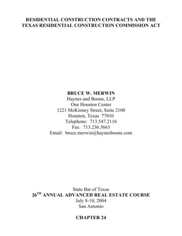
Snow LoadsANGLENote a 15% increase in the allowablecapacity of wood for loads thatinclude snow, which is a 990.910.830.750.690.63SLIDING SURCHARGEDRIFT SURCHARGEROOF SNOWNote that roofs exceeding an angle of30 degrees may reduce theground snow load.
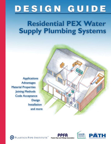
Wind LoadsZone123(Western Mass.)(Central Mass.)(Eastern Mass.)V30 (mph)708090Table 1611.3, Wind velocity “fastest mile”30 feet above the ground, exposure CMass. State Code, 6th Ed.Reference wind pressuresZone123(Western Mass.)(Central Mass.)(Eastern Mass.)Pressure (psf)1217213-second gustFastest mileAbove, Figure 1609, Basic Wind Speed (3-second gust), 33 feet above ground, exposure CIBC 2003
Unbalanced fillSoil and Surchare
Seismic?
Dead Loads3/4" wood floor3/4" wood floor/fin 3.0 psf5/8" plywood1.9 psf2x10s @ 16" o.c. 3.0 psfgyp plaster/paint 3.0 psfTotal10.9 psf5/8" plywood2x10s @ 16"o.c.strappingtar paper and shinglesshingles5/8" plywoodtar paper5/8" plywood2x12s @ 16"o.c.2x12s @ 16" o.c.Total2.0 psf (1 layer - code allows up to 3)0.7 psf1.9 psf3.5 psf8.1 psf (12.1 with 3 layers of shingles1/2" gyp. bd.ROOF(unfinished below)FLOOR5/4" deckingDECKING5/8" ceramic tile & thinset5/8" tile and thinset7.8 psf5/8" plywood5/8" plywood1.9 psf2x10s @ 16" o.c. 3.0 psf2x10s @ 16"o.c.gyp plaster/paint 3.0 psfstrappingTotal15.7 psf1/2" gyp. bd.EXTERIOR WALL1/2" gyp. bd.2x4s @ 16" o.c.wood shingles2.0 psffelt paper1.0 psf1/2" plywood1.7 psf2x6s @ 16" o.c. 1.7 psfbatt insul.0.5 psfgyp plaster/paint 3.0 psfTotal10.9 psf1/2" plywoodTILE FLOOR1/2" gyp. bd.1/2" plywoodbatt insulation & 2x6s @ 16" o.c.painted wood shingles over felt paper2x12s @ 16"o.c.5/4" decking4.2 psf2x12s @ 16" o.c. 3.5 psfTotal7.7 psfgyp plaster/paint 3.0 psf2x4s @ 16" o.c. 1.1 psfgyp plaster/paint 3.0 psfTotal7.1 psfINTERIOR WALL
BEAMSShearBending
Notching and Boringd/42"AT SUPPORT2"L/32"L/3LL/3dMAX.d/3MAX.d/3MAX.d/6MAX.
CONCENTRATED vs UNIFORMLOAD2x10 required12 feet2x6 required12 feet
LESSON LEARNEDUniform loads goodConcentrated loads more of a challenge
SIMPLY SUPPORTED vsCONTINUOUS OVER SUPPORTS2 simply supported beamsShear diagramMoment diagram1 long beam spanning over center columnHigher shear stress andreaction to columncompared to simple spanShear diagramStress reversal;compression at the top,tension at the bottomMoment diagram
Restraint against twisting &lateral stabilityAspect ratios of common beam sizes:Aspect ratio, 1.82.43.13.84.4Triple1.21.62.12.52.9 d/b 2no lateral support required 2 d/b 4ends held in position 5 d/b 6laterally restrain ends and at intervals along length of less than8ft. and compression edge held in position with sheathing 6 d/b 7laterally restrain ends both compression and tension sidesshall be supported for the entire length.
BlockingCOLUMN SUPPORTINGBEAM ABOVERIM BOARD PROVIDESLATERAL STABILITY ATEND OF JOISTBLOCK BETWEENSUPPORTING COLUMNSBLOCKING UNDERBEARING WALL ABOVEBLOCKING OVERBEARING WALL BELOWCOLUMN CONTINUING LOADFROM ABOVE TO FOUNDATION
Connections of multiple LVLsTOP LOADING BEAM2"NAIL TOGETHER TOPROVIDE STABILITYBOLTING REQUIREDTO TRANSFER LOADTO ALL BEAMS2"SIDE LOADING BEAMSUPPORTING GIRDER
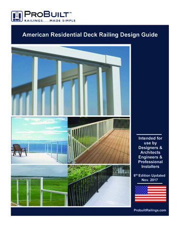
Follow the load path due to gravity450 plf150 plf30 psf30 p20 psf300 plfsf450 plf150 plf30 psf225 plf450 plf225 plf40 psf225 plf450 plf225 plfTotal 1050 plf1200 plf1050 plf
Follow the load path due to gravity450 plf150 plfAttic floor225 plf225 plf2nd floor1st floor
The simple house framing2 X1TT2s @16"O.C.2X8s @ 16" O.C.2X10s @ 16" O.C.2X10s @ 16" O.C.TOP OF SOIL10"TOP OF SLAB
Rafter/Ceiling Joist Heel JointConnectionDead and Live Loads (psf)DL LL (plf)12Roof SlopeHgHcCeiling LoadsTTΣMRidge 0 T (Hc) (DL LL)(L/2)(L/4) - RL(L/2)T RL(L/2) - (DL LL)(L/2)(L/4)HcRRRLRoof Span (L)
Redundancy Unlike bridges, houses have many structuralmembers. Credit is provided for repetitive members of joists
Laterial force resisting system Horizontal Diaphragm (plywoodsubfloor)– Collectors– Cords Vertical Diaphragm (exterior wall)– Strut– Cords The building code provides someinformation on LFRS – see WFCM.
Follow the load path due to windEast faceLeeward sideeac defiuth rd soS waeLeeac idefrth rd soN waindWWest faceWindward side
North Wind affect to HorizontalDiaphragmChordCollector (strut)
North Wind Horizontal Diaphragmaffects to West/East ShearwallsCompressionTension
A closer look at the WestShearwallShear force resisting chord forcefrom attic diaphragmShearwall cord force reactionfrom attic diaphragm(compression)E&O reaction fromshearwall aboveShearwall cord force reactionfrom attic diaphragm (tension)Shear force resisting force fromshearwall above plus 2nd floordiaphragmE&O reaction from shearwallabove added to shearwallcord force reaction from 2ndfloor diaphragm in tensionE&O reaction from shearwall aboveadded to shearwall cord force reactionfrom 2nd floor diaphragm in compression
West Wind affect to HorizontalDiaphragmCollector(strut)Chord
West Wind Horizontal Diaphragmaffects to North/South ShearwallsCompresionTension
A closer look at the North Shearwall
Wind forces normal to the wall
Designed from top to bottomConstructed from bottom to top
Shearwall anchorageSideview
Plywood diaphragmdetails12” spacing in the field6” spacing at supported edges
Plywood on exterior walls1/2" PLYWOOD2X10s7'-2"8'-1 1/2"1/2" SHEETROCK OVER1/2" STRAPPING3/4" FINISH FLOOR5/8" PLYWOOD2X10s
Plywood installation to exterior wallsPLYWOODSHEATHING1/2" GAPGALV. TAL JOINT DETAIL AT FLOOR LEVELALLOW FOR SHRINKAGE WHEN USINGCONVENTIONAL LUMBER1/8" GAPGALV. ZFLASHINGHORIZONTAL JOINT DETAIL WITHIN WALLBLOCK BEHIND HORIZONTAL PANEL JOINTS OFSHEATHING FOR ALL SHEAR WALLS
Foundation bracing(walk-out basement)STUD KNEEWALLUNBRACED ATTOP OFFOUNDATION DESIGN AS ARETAINING WALL
Foundation drainageFilter fabricWaterproofing
Addition on back ofhouseSliding and drifting snowPotential surcharge onexisting foundation wall
Adding a shed dormer
Adding a second floor
Closing in a 3-season porch Consideration of added sail area. May need to reduce size of windows or provide aconnection that will not translate at the roof. Don’t forget the roof diaphragm.
Decks Research at Virginia Tech. University, Department of WoodScience and Forest Products (see resources, “Load-TestedDeck Ledger Connection”) Loads on decks – consideration of size – new codes willrequire 100 psf for decks over 100 SF. Snow – drift & sliding? Firewood? Planters? Long-term loading such as planters more critical thansnow
Pressure Treated Wood The Z-Max is recommended by Simpson Strong-tie Stainless steel may be an option– No posted connection capacities– Limited available types– 4X
Built-up Column2-2x4 studs fastened together for a column 1-4x4 column 60% less capacity
They don’t build ‘em like thatanymore because It’s against the law.
Old house framingInstall joisthangers5x4 @ 24" o.c.Mortise and tenon cut into 6x86x8Install ledgerMay requireadditional support
Resources www.ChabotEngineering.com (slide presentation location)Massachusetts State Building Code, 6th Edition, 780 CMRhttp://www.mass.gov/bbrs/NEWCODE.HTM web version; .htm order acopy “Wood Frame Construction Manual for One- and two-family dwellings”, AmericanForest & Paper Association & American Wood Councilhttp://www.awc.org/Standards/wfcm.html “Design of Wood Structures”, D. Breyer, K. Fridley, & K. Cobeen“Design/Construction Guide – Diaphragms and Shear Walls”, APA – Thehttp://www.apawood.org/level b.cfm?content pub mainEngineered Wood AssociationThe Journal of Light Construction http://www.jlconline.com/“Load-Tested Deck Ledger Connection”, The Journal of Light Construction, March2004Fine Homebuilding nternational Building Code, 2003 http://www.iccsafe.org/International Residential Code, 2003 http://www.iccsafe.org/
Cynthia Chabot, P.E.Chabot EngineeringMelrose, Massachusetts(781) 665-7110(781) 665-7727 (fax)cchabot@chabotengineering.com
Wind Loads Above, Figure 1609, Basic Wind Speed (3-second gust), 33 feet above ground, exposure C IBC 2003 Zone V 30 (mph) 1 2 3 70 80 90 (Western Mass.) (Central Mass.)