Transcription
Pryda Timber ConnectorsBracing GuideSeptember 2016A complete guide to the design, specificationsand installation of Pryda Bracing
ESSENTIAL NOTES –PRYDA PRODUCT GUIDESINTRODUCTIONThe information in this Product Guide is provided for use inAustralia by architects, engineers, building designers, builders andothers. It is based upon the following criteria:1. No Substitution: The products covered by or recommendedin this guide must not be substituted with other products.2. Design Capacity Basis: See Codes & Standards following.3. Supporting Constructions: Constructions using Prydaproducts must be built in accordance with the NCC (BCA) oran appropriate Australian Standard. Note: This includesappropriate corrosion protection- See Corrosion Protectionfollowing.4. Correct Installation: Installation of Pryda products must bestrictly in accordance with the instructions in this guide.5. Current Guide Version Used: The current version of thisguide, including any amendments or additions, must be used.Users are advised to check the Pryda website,www.pryda.com.au, on a regular basis for the most currentdesign guides.CODES & STANDARDSProduct design capacities in this guide have been derived from:(a) Results of laboratory tests carried out by or for Pryda Australia(b) Engineering computations in accordance with the relevantAustralian Standards, ie: AS1720.1-2010 Timber Structures. Part 1: DesignMethods.AS/NZS1170 series Structural Design Actions.AS4055-2006 Wind Loads for Housing.CORROSION PROTECTIONMost Pryda products are manufactured using Z275 light-gaugesteel, having zinc coating of 275 gsm (total weight). This protectionis adequate only for INTERNAL applications in most corrosiveenvironments, except areas that are classified as heavy industrialor those subject to high humidity (eg, enclosed swimming pools).Under these circumstances, seek advice from experts as specialprotection will be required. Note: INTERNAL areas are those withinthe building envelope that are kept permanently dry.AS1684.2-2010 and AS1684.3-2010, Australian Standards forResidential Timber Frame Construction stipulate a minimumZ275 steel for all sheet metal products used in an internalenvironment.In areas outside the building envelope that are exposed torepeated wetting (EXTERNAL areas), Pryda’s stainless steelproducts or equivalent should be considered. Some alternativesinclude hot dip galvanised or powder coated steel, which are notsupplied by Pryda. For more detailed information, read Pryda’sTechnical Update on Corrosion Resistance of Pryda Products orcontact a Pryda office.PRODUCT CERTIFICATIONPryda Australia warrants: This warranty applies only to: Design capacities tabulated in this guide apply directly forCategory 1 joints. For all other joints, reduce design capacities byusing the factors as specified in General Notes (if applicable).Design capacities are related to the Joint Group of the timber asdefined in AS1720 and AS1684. If the Joint Group of timbermembers joined together varies, the lower group must be assumedfor design, for example, JD5 is lower than JD4.DEFINITIONSSpecial terms used in this guide are as defined in AustralianStandards, including:Design Capacity: The maximum Limit State Design load (aka“action”) which the product can safely support under the specifiedload condition, eg, 1.2G 1.5Q (dead roof live). See GeneralNotes for details (if applicable).Joint Group: Classification of a timber according to its fastenerholding capacity. See General Notes for details (if applicable)Products in this guide are free from defects in the materialand manufacturingDesign capacities are in accordance with test results orcurrent, relevant Australian Standards and the Building Codeof Australia.Pryda products are structurally adequate provided they aredesigned, installed and used completely in accordance withthis guide. Products in this guide.Products used in the specified applications and notdamaged after manufacture and supply.Joints free from wood splitting, decay or other timber defectsat the joint or within 150 mm of the joint.INSTRUCTIONS FOR INSTALLATIONThese notes are provided to ensure proper installation.1. All fasteners used must be manufactured by reputablecompanies and be of structural quality.2. Connectors must not be installed on timber which is split beforeor during installation. If the timber is likely to split as fastenersare driven, fastener holes must be pre-drilled.3. Do not overload the joints during construction or in service.4. Hole diameter for bolts in seasoned timber must not be morethan 1.0 mm larger than the bolt diameter to achieve a snugtight connection. Specified washers must be installed againstthe timber face.5. Use proper safety equipment and due care in installing theseconnectors.6. Any gaps in joints between the timber members must not exceed3 mm.7. Do not over-tighten screws.Copyright: Pryda Australia - A Division of ITW Australia – ABN 63 004 235 063 - 2016
PRYDA TIMBER CONNECTORSBracing GuidePryda Bracing GuideTABLE OF CONTENTSGENERAL NOTESUseful notes and definitions fore effective reading of this guide4PRYDA ANGLE BRACEA formed steel section brace in two sizes,ie, Mini Brace and Maxi Brace for use as wall bracing and noggin5PRYDA STRAP BRACEA flat, tensioned steel strap in six section sizes for all bracing uses6PRYDA SPEEDBRACEA formed steel tension brace for roof and other bracing uses8WALL BRACING DETAILSDetails of A Types and B bracing units9TECHNICAL INFORMATIONTension capacities for all bracing products12PRYDA SHEAR CONNECTORSFixed to the top plate of non-bearing bracing walls to transferracking loads from ceiling plane14RAMSET ANKASCREWSConcrete anchor screws for tie-down of bracing unitsAPPENDIXProvides information and recommendations on design, constructionand engineering matters related to the bracing of walls in timberframed constructionProduct Information UpdatesInformation contained in this product guide is subject to change.The latest updates are available from www.pryda.com.au.1617
PRYDA TIMBER CONNECTORSBracing GuideGENERALFor more than 30 years, Pryda bracing productshave been developed to be structurally sound andcost effective for the bracing of roofs, walls, floorsand other parts of timber framed buildings. They aredesigned to meet code bracing requirements andhave been laboratory tested to assure theirstrength.Specification for Pryda BracingAll Pryda bracings are manufactured from G300 Z275 ZincForm steel or equivalent for highstrength and corrosion resistance in normal, interioruses. Higher levels of zinc coating or epoxy paintsare also available to suit use in corrosiveenvironments such as near the sea front.Product details are tabulated in the Pryda PriceList and Pryda Catalogue publications.Which Bracing to Use?Pryda Timber Connector NailsFor fixing of all Pryda bracings, itis essential to use galvanisedPryda Timber Connector Nails,ie, the special 35 x 3.15 mm nailsdeveloped by Pryda specificallyfor fixing of our products.Laboratory strength testing hasshown that clouts are notPryda Timberadequate for this purpose as theirheads may pop off under less than Connector Nailsdesign load.Machine Driven Nail UseWhere appropriate, 32 x 2.3 mm Duo-Fast C SHEG(ie, screw hardened electro galvanized) machinedriven nails (code D40810) or equivalent may beused instead of the specified 35 x 3.15 mm PrydaTimber Connector Nails to fix Pryda connectorsprovided that: One additional nail than specified in the bracingdetails (eg, 2 instead of 1, 3 instead of 2, 5instead of 4 etc.) Machine driven nails are driven at nail spacingsand edge distances similar to the hole pattern,ensuring that these nails are not driven into theholes or located not closer than 5mm from theedge of a hole.Collectively, Pryda bracings are suited to allcommon bracing uses in timber framing.Application Suitable BracingFloor joistsStrap BraceWallsAngle Brace, Strap Brace,SpeedbraceRoof trusses Speedbrace*, Strap Brace* Recommended for this use.For bracing of walls in accordance with AS 1684Residential Timber-framed Construction, see thePryda Wall Bracing Unit Construction Guideavailable in this document (from page 8 onwards).A guide to bracing roof trusses is included inAS4440:2004 Installation of Nailplated TimberTrusses. Speedbrace is usually preferred to StrapBrace for this use because of its specialadvantages.Pryda bracings can also be used for someuncommon applications, depending on the designstrength required. For this reason, DesignCapacities are included in this publication.Note: Extreme care must be taken when usingmachine driven nails as the prevailinginstallation practices tend to inhibit compliancewith the above requirements.Some of other pneumatic coil screw hardened nailsconsidered equivalent to Duo-Fast D40810 arePaslode 32 x 2.5 mm (B25110), Duo-Fast 32 x 2.5mm (D41060), Paslode 40 x 2.5 mm (B25125) andDuo-Fast 40 x 2.6 mm (D42360).Fixing into Steel Supporting StructurePryda products can be fixed into steel using BuildexTeksTM screws or similar.Information on fixing Pryda bracing products to steelframing is available in the publication titled DesignGuide – Pryda Connectors for Steel Framing.Material ThicknessAll material thicknesses referred to in this guide arethe total coated thickness. This includes the zinccoating thickness, which is typically around 0.04mm for Z275 steel.3PRYDA BRACING GUIDE – SEPTEMBER 2016
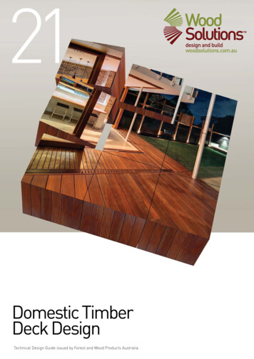
PRYDA TIMBER CONNECTORSBracing GuideInstallationGood installation of bracings is most essential.Pryda recommendations as specified in this guide.Particularly important are:Nailing: Keep the nails away from ends or edgesof timber to assure good nailholding.Brace Angle: Install the brace at an angle ofbetween 40 and 50 degrees to the horizontal ifpossible. Otherwise, the minimum is 30 degrees,maximum 60 degrees.Strap Tensioning: Ensure each length of StrapBrace has a Pryda Tensioner, properly tightenedprior to nailing. Tension Speedbrace by hammeringit flat over each stud and wall plate.Angle Brace Slots: Don’t overcut the slot (notch)for the brace as this will weaken the studs. 20 mmis the required maximum slot depth for both Mini andMaxi Brace. As Mini Brace has a shorter leg (16mm), the studs can be checked 3 mm so that thebrace and nails are installed flush with the stud edge(pictured). Maxi Brace must not be checked(rebated) into the stud edge because the notchdepth would then exceed the 20 mm maximumspecified in AS1684.Note: Information about suitable equipment forcutting checks in the studs for Angle Brace isavailable from Pryda.Max notch20 mmPryda MiniBrace checkedinto stud so thatbrace and nailsare flush withstud faceMax notch20 mmPryda MaxiBrace notcheckedinto studSee also: Pryda Installation Guide for Prefabricated Walls with Pryda Bracing.SizesPRYDA ANGLE BRACEAvailable sizes are:Pryda Mini Brace 18 x 16 x 1.2 mmPRODUCTCODELENGTHMB36 MB42 MB483.64.24.8Tied in bundles of 10 lengths.Pryda Maxi Brace 20 x 18 x 1.2 mmPRODUCTCODEAB36AB42LENGTH3.64.2Tied in bundles of 10 lengths.AB484.8InstallationUsesPryda Mini Brace and Maxi Brace can be used asbracing or nogging of Type A Bracing Units in wallframes in accordance with AS1684-2010Residential Timber-Framed Construction and theWall Bracing Units Construction Guide.PRYDA BRACING GUIDE – SEPTEMBER 2016As bracing or nogging, Pryda Angle Brace can beinstalled either sitting on the surface of the timberframing or checked in flush with the surface using achisel or a checking head on a circular saw. Toinstall Angle Brace:1. Square up the wall or temporary frame readyfor bracing.2. Use the edge of the brace to draw a straightline where the brace or nog is to go, and cut theslots. Note that the brace angle must be from30 to 60 degrees to the horizontal and ends ofthe brace should be 150 mm minimum from theend of the plate.3. Fit the brace into the slots with the the verticalleg downwards for safety reasons. Fix it withone Pryda Timber Connector Nail per studand two Pryda Timber Connector Nails per wallplate.4
PRYDA TIMBER CONNECTORSBracing GuideStrap Brace Tensioners:PRYDA STRAP BRACE ANDTENSIONERSPRODUCTCODEIncludes wing nut, bolt and washer.30 in carton (6 per pack x 5 packs)Includes bolt. 30 in carton (6 perpack x 5 packs)includes wing nut, bolt and washer.100 per packSBTWING NUT nutsert)includes bolt. 100 per packBolt Specification: M6x30 T-bolt for SBT/SBT100 andM6x30 hex-head bolt for the nutsert type SBT30N/SBT100N.Uses & AdvantagesStructural PerformancePryda Strap Brace with Tensioner, is an easy-to-use,flat strap steel bracing for roofs, walls, ceilings andfloors. Strap Brace complies with the wall bracing rulesof AS1684 Residential Timber-framed Constructionand has excellent advantages, including:Saves on-site labour time as studs do not haveto be notched. The unnotched studs can often bea smaller size and hence cheaper than notchedstuds.Available in long length coils for ease of handlingand minimum wastage.Easily and quickly tensioned using the StrapBrace Tensioner - simply by driving the hex-headscrew (nutsert option) or turning the wing nut(wingnut and t-bolt option).Pryda Strap Brace takes load in tension only and musttherefore be used in pairs, in opposing diagonaldirections. It must also be sufficiently tensioned to takethe load without distortion of the frame.Pryda Strap Brace is ideal for bracing applicationswhere timber braces are not feasible because of theirthickness or because timber can’t be bent, eg, exposedbeams or rafters, or trusses.SizesAvailable sizes are:PRODUCTCODESB082/15 **SB082/30 SB083/3.5ARTICLE & SIZESB083/3.5W-500SB083/4.0W-50030 x 0.8 mm x 3.5 m lengths30 x 0.8 mm x 4.0 m lengths30 x 0.8 mm x 30 m lengths(unpunched straping)GUS083/3025 x 0.8 mm x 15 m coil25 x 0.8 mm x 30 m coil30 x 0.8 mm x 15 m coil30 x 0.8 mm x 30 m coil30 x 0.8 mm x 50 m coil30 x 1.0 mm x 30 m coil30 x 1.0 mm x 50 m coil32 x 1.2 mm x 30 m coil30 x 0.8 mm x 3.5 m lengths** SB082 product is not recommended for standard bracing units.Installation Of Strap BraceFloor BracingPryda Strap Brace of any size, can be used as aherring-bone bracing for floor joists - as illustrated. Atensioner is not required for this use.1.2.Fix the ends of both lengths of Strap Brace to thetop and bottom of the first joist with two PrydaTimber Connector Nails per joint.Pull each length of Strap Brace down from the topedge of the joist or up from the bottom onto thenext joist. Tension it using a screw driver or similartool and fix with one Pryda Timber Connector Nailat each joist.For floor systems with trusses, I-joists or deep beams,bracing is required for both: (a) stability duringconstruction and (b) wind resistance during the life ofthe building. The bracing can be Pryda Strap Brace orUnpunched Strapping. It is to be fixed to the floormembers and supporting structure with 35 x 3.15 mmPryda Timber Connector Nails or power driven 2.5 mmor 2.87 mm nails (as shown opposite).Fix Strap Brace with 2/3.15Ø x 35mmPryda Nails to Truss Top ChordMax. 2700mm CentresWrap Pryda Brace SB123 Under TopWall Plate and fix with 3.15Ø x 35mmPryda Nails, 2 Nails Into Side and 4Nails to UndersideFloor Bracing at External Wall5PRYDA BRACING GUIDE – SEPTEMBER 2016
PRYDA TIMBER CONNECTORSBracing GuideWall BracingFor details of bracing units see pages 9 to 11:1.2.3.4.5.6.7.Make sure that the wall frame is close to square.For Type B units, wrap the brace over the plate. Nailthe end of the Strap Brace to the top plate within150 mm of a stud using:- three Pryda Timber Connector Nails for Type Aunits or- four Pryda Timber Connector Nails for Type Bunits.Lay the Strap Brace across the frame at an angle of45 degrees approximately (30 to 60o) and with theunfixed end on the bottom plate at within 150 mm ofa stud and allowing a length of strap to wrap aroundthe plate. Cut the strap brace to length.Straighten and partially tighten the Strap Brace bypulling it down onto the bottom plate. For Type Bunits, wrap the brace over the plate. Fix the end ofthe Strap Brace to the plate within 150 mm of a studusing Pryda Timber Connector Nails with:- two nails for Type A units or- four nails for Type B units.Fix the second length of Strap Brace in the samemanner, diagonally opposing the first length.Fit and tighten the tensioners on both braces, withthe tensioner facing into the frame. Adjust thetensioner as required or until the brace is taut. Note:Do not use Strap Brace to plumb the frame.Nail both braces to every stud crossed using ONEPryda Timber Connector Nail for both Type A andType B units.The required minimum number of bracing units isspecified in AS1684.Fixing to bottom plateRoof BracingTo brace standard trusses, rafters or roof beams:1. Use only SB123 Strap Brace (or Speedbrace) forroof bracing. Refer to AS4440-2004 or Pryda TrussInstallation Guide to establish whether single ordouble Strap Brace is required based on roof span,pitch and wind speed.2. Lay out diagonal opposing lengths of Strap Brace ontop of the roof framing at a maximum angle of 30degrees (measured on plan) to the ridge line. Bracesare required on both sides of the ridge line and atboth ends of the roof.3. Fix Strap Brace at both ends by wrapping one endaround the top wall plate and the other end aroundthe rafter, roof beam or top chord of a truss at theridge, and by nailing each end using the requirednumber of Pryda Timber Connector Nails.4 Fit and tighten the tensioners on both braces, withthe tensioner facing down into the roof space. Adjustthe tensioner as required or until the brace is taut.Note: Do not use Strap Brace to plumb the frame.5 Nail both braces to every truss or rafter crossedusing two Pryda Timber Connector Nails percrossing.For more details of requirements for roof truss bracingrefer to the Pryda’s Roof Truss Installation Guide orto AS4440.Two Nails toTop Chord45OHammer Fixing to Top PlateAnchorage Point - Bend Steel Brace to Side of Top Plate AndUnder Plate. Fix With Five Nails to Top Plate. Nails Shall beno Closer Than 10mm to The Edge of The Timber.End Fixing Detail on Rafter TrussesRefer to AS4440-2004 for Other Fixing Details.Pulling Out the BracePRYDA BRACING GUIDE – SEPTEMBER 20166
PRYDA TIMBER CONNECTORSBracing GuidePRYDA SPEEDBRACEFixing at Apex and IntermediatePryda Speedbrace, used as diagonal roof bracing,provides overall stability to the trussed roof and inconjunction with the roof battens, prevents lateralbuckling of the top chords. Pryda Speedbrace is alsosuitable for use as wall bracing.AdvantagesPryda Speedbrace is applied on top of the top chord,eliminating the difficulty of applying a brace to theunderside of the chord as is necessary withconventional timber braces. The profile of Speedbraceallows it to be applied without the need for tensionersas the rib merely needs to be hammered flat where itcrosses the timber members.In addition, Speedbrace can be spliced easily and canbe wrapped around members to provide sound andsecure anchorage.Fixing at EndsFixing at EndsSizesAvailable sizes of Pryda Speedbrace are:CodeLengthSDB36SDB40SDB50SDB603.64.05.06.0Tied in bundles of 10 lengths.Splice DetailRoof BracingRefer to AS4440 for all other fixing details.Pryda Speedbrace can be installed as for Strap Brace,where Speedbrace crosses each truss it is hammeredflat and nailed with two galvanised Pryda TimberConnector Nails at each truss crossed.Pryda Speedbrace is spliced by overlapping lengthsof brace hammering flat and nailing with the samenumber of galvanised Pryda Timber Connector Nailsas is required at the top plate (see diagram below).7PRYDA BRACING GUIDE – SEPTEMBER 2016Wall BracingPryda Speedbrace may also be used to brace wallframes.
PRYDA TIMBER CONNECTORSBracing GuideWALL BRACING UNIT CONSTRUCTION GUIDESection 8 of AS1684:2010 – Residential Timber-Framed Construction specifies methods of determining the requiredminimum amount of permanent wall bracing, ie:Simplified method (Part 4 of AS 1684): The number of Type A bracing units included in each plan direction mustcomply with Table 8.2 – which depends on the overall size of the walls. Details of Type A bracing units are specifiedin Table 8.3 – and in this document.Other constructions (Part 2 or 3): The designer must either:* Calculate the design horizontal wind force (“total racking force” -kN) and the total capacity of the bracing includedin each plan direction to resist this force, or* Look up the wind force in Appendix G of the code and ensure by calculation that the total capacity of the bracingexceeds this force.Details of wall bracing units and their capacities (in kN/m) are specified in Table 8.18 – and in this document.The “Simplified method” applies only to non-cyclonic wind zone N1 or N2 and to buildings of limited size – seeClause 1.6 of Part 4 of the code.This guide provides full details of how bracing units (or “panels”) can be constructed in accordance with AS 1684using Pryda Bracings, Stud Ties, Strap Nails and Pryda Timber Connector Nails. The details specified in AS1684are based on the results of test on such units. Bracing capacities are for units with a lining such as plasterboardinstalled. During construction, additional temporary bracing may be required until the lining is fully installed. Forinformation on the derivation of unit capacities, contact Standards Australia.Wall Bracing Units - DetailsMini Brace, Two Lengths, Type A UnitThis bracing unit comprises two sections of the same wall with Pryda Mini Brace braces in opposing diagonals, asshown below. These two wall sections are considered to work together. AS1684 has a maximum wall height of 3.0m (except at gable or skillion ends). Design capacity of these units is 0.8 kN/m for wall heights up to 2.7 m and and0.72 kN/m for 3.0 m height. The table values given below are the total capacity from both wall sections andassumes that both wall sections are of equal length.Wall Height Bracing capacity (kN) for Bracing length of EACH Wall Section .6Note: For walls higher than 2.7 m,reduce the bracing unit’s capacity ininverse proportion to the wall height, eg,for 3.6 m walls, take 2.7/3.6 0.75times the capacity for 2.7 m heightThe nails used must be galvanised Pryda Timber Connector Nails, code OSNG, size 35 x 3.15 mm.Timberor PrydaMiniBraceNoggingOnePrydaNail ateachstudTwo PrydaNails inbrace endsFix wall platesto studs as normalOR Use PrydaST3 Stud TiesPrydaMini BraceBrace angle30 to 60 degs,preferably40 to 50 degsPryda MiniBraceJoint DetailBrace: Pryda Mini BraceFixing: Two Pryda Nails each endOne Pryda Nail each stud1.8 to 2.7 m max.1.8 to 2.7 m max.Note: A minimum 3.6 m wall length (i.e using two 1.8 m units with Mini Brace as opposing diagonals) will be required to accommodatethis type of bracing unit. Accordingly, a minimum 5.4 m wall length is required to achieve a maximum capacity of 4.1 kN (see table)PRYDA BRACING GUIDE – SEPTEMBER 20168
PRYDA TIMBER CONNECTORSBracing GuideStrap Brace/Speedbrace Type A Unit (Racking Capacity 1.5 kN/m)This bracing unit comprises one section of the wall, with cross-over braces of Pryda Strap Brace or PrydaSpeedbrace as shown below. The minimum recommended Strap Brace size (SB083) fully complies withAS1684.2:2010 and AS1684.3:2010 specifications. Maximum wall height in AS1684 is 3.0 m (except at gable orskillion ends). Design capacity is 1.5 kN/m for wall heights up to 2.7 m and 1.35 kN/m for 3.0 m height.Wall HeightBracing capacity (kN) for Bracing length .6Note: For walls higher than 2.7 m, reducethe bracing unit’s capacity in inverseproportion to the wall height, eg, for 3.6 mwalls, take 2.7/3.6 0.75 times thecapacity for 2.7 m heightThe nails used must be galvanised Pryda Timber Connector Nails, code OSNG, size 35 x 3.15 mm.Maxi Brace, One Length, Type A Unit (Racking Capacity 1.5 kN/m)This bracing unit comprises one section of the wall, with one brace of Pryda Maxi Brace, as shown below. Maximumwall height in AS1684 is 3.0 m (except at gable or skillion ends). Design capacity is 1.5 kN/m for wall heights up to2.7 m and 1.35 kN/m for 3.0 m height.Wall HeightBracing capacity (kN) for Bracing length .6Note: For walls higher than 2.7 m, reducethe bracing unit’s capacity in inverseproportion to the wall height, eg, for 3.6 mwalls, take 2.7/3.6 0.75 times thecapacity for 2.7 m heightThe nails used must be galvanised Pryda Timber Connector Nails (OSNG) size 35 x 3.15 mm.See JointdetailsPrydaMaxi BraceBrace angle30 to 60 degs,preferably40 to 50 degsTimberor PrydaMiniBracenoggingTwo PrydaTimberConnectorNails at eachstud andwall platePryda Maxi BraceSee JointdetailsSee Jointdetails1.8 to 2.7 m max.9Pryda Strap Nail SN2C orSN2B on both sides ofthe framePryda Stud TieST3 or ST4 orSTS3PRYDA BRACING GUIDE – SEPTEMBER 201630Two PrydaTimberConnectorNails ateach stud &wall platePryda Maxi BraceNote: Pryda Ezi Stud Tie (SST) may be used in lieu ofthe other stud ties specified above.
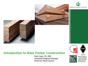
PRYDA TIMBER CONNECTORSBracing GuideType B Unit (Racking Capacity 3.0 kN/m)This Type B bracing unit uses Pryda Strap Brace (SB103) or Pryda Speedbrace, a steel brace thicker than theone used for Type A units. Note: Pryda Strap Brace (SB083) may also be used provided the below table values arereduced by 20%. Maximum wall height in AS1684 is 3.0 m (except at gable or skillion ends). Design capacity is 3.0kN/m for wall heights up to 2.7 m and 2.7 kN/m for 3.0 m height.Wall HeightBracing capacity (kN) for Bracing length .3Note: For walls higher than 2.7 m, reducethe bracing unit’s capacity in inverseproportion to the wall height, eg, for 3.6 mwalls, take 2.7/3.6 0.75 times thecapacity for 2.7 m heightThe nails used must be galvanised Pryda Timber Connector Nails (OSNG) size 35 x3.15 mm.ST3ST3Pryda Strap BracePrydaStrapSB103 orBraceSB103Speedbraceor(see Note below)SpeedbraceTimber orPryda MiniBraceNoggingSee JointDetailsST3 or STS3 Pryda Stud Tieor one SN2 Strap Nail oneach wall faceSee JointDetailsTwo PrydaPrydaOneTimberConnectorNails intoeach studBrace angle30 to 60degrees,preferably40 to 50 e: Prydaor Speedbraceor orNailsNails:Fixing: Prydawith 4 nailsat each -endand 1end,nail -at2each4 eacheachstud.stud1.8 to 2.7 m max.Note: Pryda Strap Brace (SB083) may also be used provided the abovetable values are reduced by 20% or adopting a capacity of 2.5 kN/m.Pryda BraceJoint DetailST3ST3Four Pryda TimberConnector Nails intowide face of top andbottom wall plates.Note: Pryda Ezi Stud Tie (SST) may be used in lieu ofthe other stud ties specified above.Narrow Bracing UnitsPryda has developed the Pryda Wall Truss Brace (PWTB) to cater for narrow wall lengths, adopting a similar profileto a floor truss. Three types of units are available, PWTB1/PWTB2 to resist up to 5.0 kN/m and PWTB3 to resist upto 14.0 kN/m racking loads. For detailed information on the PWTBs, refer Design Guide on Pryda Wall Truss Brace.Also available is a series of Narrow Bracing Units using Strapbrace/Speedbrace. Details of these units are availablein a separate publication tiltled Pryda Design Guide for Narrow Wall Bracing Units.Pryda Wall Truss Brace (PWTB)for narrow wall bracing applicationsPRYDA BRACING GUIDE – SEPTEMBER 2016Narrow Bracing Unit10
PRYDA TIMBER CONNECTORSBracing GuideTECHNICAL INFORMATIONPryda’s recommendations for materials, installation and design loads are given in the following topics.MaterialsAll Pryda bracings are manufactured from G300 -Z275 ZincForm steel or equivalent for high strength andcorrosion resistance in normal, interior uses.The Pryda Bracing products included in these units are:Brace ProductDetailsProduct CodeMini Brace18 x 16 x 1.2 mm Angle BraceMB36, MB42, MB48Maxi Brace20 x 18 x 1.2 mm Angle BraceAB36, AB42, AB48Speedbrace37 x 1.0 mmSDB36, SDB40, SDB50, SDB60Strap Brace30 x 0.8 mm, 30 x 1.0 mm, 32 x 1.2 mmSB083, SB103, SB123Warning: For the construction of bracing units don’t use Hoop Iron and beware of 0.6 mm thickness (or thinner) non-engineeredbracing. The latter material may be offcuts of Zincalume or Colorbond which are roofing materials having little or none of thesacrificial protection to cut edges which is a feature of the Galvabond (or equivalent) material used for Pryda products. Thisprotection is required for good corrosion resistance in contact with mortar.All nails used for bracing units must be hand-hammered galvanised 35 x 3.15 mm Pryda Timber Connector Nails(OSNG). Pryda will not support the use of other nails unless they meet the requirements for machine driven nails inpage 4.Compression Capacities:DESIGN CAPACITIESStud SpacingPryda tests and computations have established thefollowing Limit State Design capacities for Prydabracings.For the brace to develop tabulated tension orcompression capacities, it must be anchoredadequately at each end. In the case of Speedbraceor Strap Brace product, it is necessary to bend thebrace around the anchor points to achieve thedesignated tension capacities. Angle Braces onthe other hand are often governed by the end fixingcapacity (nail capacities) as they cannot be bent atanchor points.Tension Capacities:CodeCross SectionDesign TensionCapacity (ΦNj) kNAngle Brace (Mini and Maxi Brace)MB18 x 16 x 1.2 mm7.8AB20 x 18 x 1.2 mm9.5SpeedbraceSDB37 x 1.0 mm8.7SB08225 x 0.8 mm3.5SB08330 x 0.8 mm5.2SB10330 x 1.0 mm6.8SB12332 x 1.2 mm9.4Strap Brace11PRYDA BRACING GUIDE – SEPTEMBER 2016Maxi Brace Design CompressionCapacity (ΦNj) (kN) at:(mm)Parallel to Brace45o4503.72.66002.71.9Note:As noted previo
Most Pryda products are manufactured using Z275 -gauge light steel, having zinc coating of 275 gsm (total weight). This protection . Z275 steel for all sheet metal products used in an internal . A guide to bracing roof trusses is included in AS4440:2004 . Installation of Nailplated Timber