Transcription
NXP SemiconductorsDocument Number: AN5408Application NoteRev. 6, 09/2018S32K1xx Clock Calculator GuideHow to use S32K1xx tool to easily calculate device frequency domainsby:NXP Semiconductor1 IntroductionContents1 Introduction. 1The S32K1xx is NXP’s 32-bit general purpose MCU family for automotive andindustrial applications. Our offer combines the latest 90nm technologies so thatcustomers will not have to compromise performance in exchange for low powerconsumption. The S32K1xx is built upon the ARM Cortex-M4 , running at upto 112 MHz. This device family consists of two subfamilies: S32K14x and theS32K11x. The S32K14x series is the performance-grade line, comprising thedevices S32K142, S32K144, S32K146, and S32K148; while the S32K11x(S32K116 and S32K118) is the low-cost sub-family for users who wish tooperate at a lower price point but with a reduced feature set. For simplcity'ssake, this application note will refer to the S32K1xx family as "S32K".2 Clock calculator design. 23 Clock tool example use case:Configure LPSPI to SPLLBUS CLK at 48 MHz andperipheral clock at 24MHz FIRCin RUN mode on S32K14x.154 Conclusion. 315 Revision history.31This device supports four clock oscillators and, in S32K14x, one system phase locked loop (SPLL) for a total of up to five clocksources. There are also multiple input pins through which external clock signals can be driven into the MCU. Of the four oscillators,there is a system oscillator (SOSC), a 48 MHz fast internal RC oscillator (FIRC), a 2-8 MHz slow internal RC oscillator (SIRC),and a 128 kHz low power oscillator (LPO). The SOSC can source from either a signal driven into the EXTAL pin or a crystaloscillator connected to the XTAL and EXTAL pins (henceforth referred as simply “XTAL”). EXTAL can support up to 50 MHz, whilethere are two ranges that are allowed for the XTAL depending on configuration: 4-8 MHz or 8-40 MHz; FIRC can be trimmed to48 MHz; SIRC can be either 2 MHz or 8 MHz. In addition, the SPLL on S32K14x devices supports frequencies from 90 MHz to160 MHz. See the following table for a summary.Table 1. S32K clock source frequenciesClock SourceAllowed FrequenciesFIRC48 MHzSIRCSelectable among 2 and 8 MHzLPO128 kHzSPLL (S32K14x only)90-160 MHzSOSCSelectable between XTAL and EXTALXTALSelectable ranges: 4-8 MHz and 8-40 MHzEXTALUp to 50 MHzClock setup is a necessary step in almost all applications. The S32K clock calculator seeks to complement the configurationinstructions in the reference manual by providing a graphical, interactive tool to help users find the correct register configurationin order to achieve their desired clock frequencies.Accompanying this application note is the clock calculator. You can download it from S32K1xx Clock Calculator.
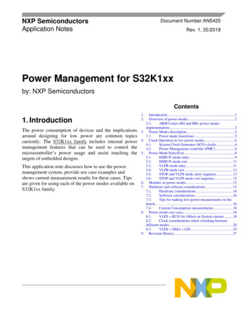
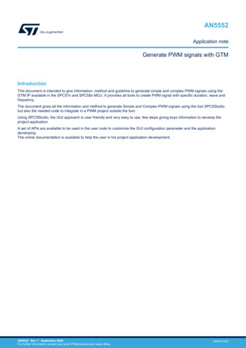
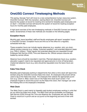
Clock calculator designThe clock calculator makes use of macros to perform functions like resetting the spreadsheet to initial values, configuring all clockfrequencies to the maximum allowable settings, and copying generated code. Macros must be enabled in the user's MS Excel toaccess these features. If macros are turned off however, the tool will still be able to calculate clock frequencies, but theaforementioned features will be disabled. To turn on macros in MS Excel 2016, go to the Developer tab on the top toolbar andclick on Macro Security. A popup window will appear. In it, select Enable all macros.Figure 1. Enabling macros2 Clock calculator designThe S32K clock calculator takes the form of an interactive Microsoft Excel spreadsheet, organized into multiple tabs as shown inthe following figure.Figure 2. S32K1xx clock calculator setupClock sources (i.e. oscillators, SPLL, external input pins) propagate to the various clock domains from which the MCU modulestake their clocks. Most cells representing clock domain frequencies are not to be modified manually. The user is meant to enterfrequencies to the few select clock sources and all clock domain frequencies derive from these sources. Several clock domaininputs are meant to be modified manually as they represent external clocks that are driven into the chip. There are also input cellsthat set muxes and clock dividers. All cells that take user inputs have blue borders instead of black, shown below. Blocks thatrequire inputs also show the register fields that the blocks represent.S32K1xx Clock Calculator Guide , Rev. 6, 09/20182NXP Semiconductors
Clock calculator designFigure 3. Input cells vs. Output cellsThere are limits to what frequencies can be entered to the input frequency cells. Values that are out of range will be rejected andthe user will receive an error message. Invalid clock domain frequencies that arise from valid input values and legal, but improper,dividers will be shaded in red. This is explained in greater depth later in this application note.Frequency values are linked across tabs, so BUS CLK in the Tree tab will always be the same as BUS CLK in the ModuleDomains tab. Hyperlinks are provided to duplicate domain names to link back to their points of origin. For example, BUS CLKoriginates in Tree. So clicking the BUS CLK textbox in Module Domains will take the user to BUS CLK in Tree. Textboxes thatare links, when hovered over, will cause the mouse cursor to turn into a hand icon and a pop-up to appear, showing the addressof the destination, as shown in the following figure.Figure 4. Clicking on a linkS32K1xx Clock Calculator Guide , Rev. 6, 09/2018NXP Semiconductors3
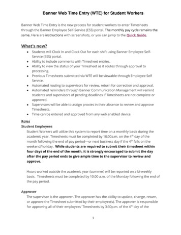
Clock calculator designThe following subsections will explain in depth the purpose of each tab.2.1 TreeTree is the centerpiece of the tool. This tab is the starting point for all clock frequency calculations. It is organized to resemble theS32K clock tree, as presented in the following figure.SCG xCCR[SCS]SCGFastIRC(where x R, V, or H)SCG xCCR[DIVCORE]PLLAnalogPREDIVVCO CLK 2DIVCORESPLL CLK0110BUS CLKDIVBUS0011SlowIRCSCG xCCR[DIVBUS]00100001System PLLclock monitor(Loss of lock)SGG TCLKCORE CLKSYS CLKFLASH CLKDIVSLOWSCG xCCR[DIVSLOW]SCG SLOW CLKSCG SPLLDIV[SPLLDIV1]System OSCClock Monitor(Loss of clock)SPLL CLK(SOSC is monitored,SIRC is module clock)DIV1SPLLDIV1 CLKDIV2SPLLDIV2 CLKSCG SPLLDIV[SPLLDIV2]FIRC CLKSCG FIRCDIV[FIRCDIV1]DIV1FIRCDIV1 CLKDIV2FIRCDIV2 CLKAsynchronousPeripheralSourcesSCG FIRCDIV[FIRCDIV2]SCG SIRCDIV[SIRCDIV1]SIRC CLKSCG SOSCCFG[EREFS]EXTALOSCSOSCDIV1SIRCDIV1 CLKDIV2SIRCDIV2 CLKSCG SIRCDIV[SIRCDIV2]0SOSC CLK1SCG SOSCDIV[SOSCDIV1]00000110XTAL0001DIV1SOSCDIV1 CLKDIV2SOSCDIV2 CLKSCG SOSCDIV[SOSCDIV2]00100011100SCG CLKOUT010001SCG CLKOUTCNFG[CLKOUTSEL]PMCLPO128KhzRTCLPO128K CLK 4000DIVCLKOUT101110LPO32K CLK111SIM CHIPCTL[CLKOUTSEL]0001RTC CLKINSIM CHIPCTL[CLKOUTDIV]011RTC CLKLPO128K CLK1011SIM LPOCLKS[RTCCLKSEL] 32LPO32K CLKLPO1K CLK000110LPO CLK11SIM LPOCLKS[LPOCLKSEL]RTC1 kHz ClockRTC CLKOUTRTC CLKFigure 5. S32K Reference Manual clock treeFigure 5 shows, in part, the diagram’s clock tool counterpart. Additions were made to the Tree diagram to reflect the nuances thatare not shown in the reference manual graphic. For the sake of simplicity, the reference manual graphic displays only the essentialfeatures. This tool consolidates all clocking options into a single platform.S32K1xx Clock Calculator Guide , Rev. 6, 09/20184NXP Semiconductors
Clock calculator designFigure 6. Clock calculator treeThis tool’s version is obviously a lot more complex than in the reference manual. In fact the screenshot could only reasonablydisplay the top-left section of the diagram. The flow of the diagram generally goes from left to right. On the left are the S32K clocksources and on the right are the clock domains. MCU modules run on one or more of these clock domains.Clock domain frequency values are displayed in the outlined cells next to their labels. Most cells are not meant to be written to,their values are dependent on the frequencies of preceding steps in the clock tree. Take BUS CLK, for example: its value dependson the system power mode, the core clock divider, the system clock selector, and the controller of the source selected by thesystem clock selector. The system clock selector can choose either the SOSC, SIRC, FIRC, or the output of the SPLL. Now lookat one of the sources, the FIRC block. FIRC is trimmed to 48 MHz but the frequency that propagates depends on the next block,FIRC Enable. Therefore the actual input frequency received by blocks that take the FIRC as a source is the FIRC frequency of48 MHz, filtered by FIRC Enable. The same goes for SOSC, SIRC, and LPO. The SPLL output is configured in the SPLL tab.BUS CLK selects from these four clock sources by selecting the value of the System Clock Selector block. Then finally theselected signal is divided by the core clock prescaler value and filtered by the system mode.This tab also features two buttons, Reset and Max. They only have function when macros are enabled. Clicking on these buttonswith macros disabled will return an error. If macros are enabled, the Reset button will set all blocks to their reset value, as describedin the reference manual. The Max button sets all blocks in this tool to values that configure the system and auxiliary clock domainsto their respective maximum allowable frequencies. Below is a screenshot of the buttons.S32K1xx Clock Calculator Guide , Rev. 6, 09/2018NXP Semiconductors5
Clock calculator designFigure 7. Buttons2.2 Device selectThe Device Select tab selects between the two S32K subfamilies. S32K11x lacks the SPLL, the HSRUN power mode, and severalmodules compared to the S32K14x. Since this tool visualizes the fully featured S32K14x, when S32K11x is selected, S32K14xonly features are turned off. This means that the SPLL output will be set to 0 and unavailable as a clock source, power modeblocks will be shaded red if the HSRUN power mode is selected, and S32K-only peripherals will have their clocks zeroed out aswell.Figure 8. S32K device select2.3 Oscillator source controlS32K’s external oscillators have a comprehensive set of options that warrants a separate tab. These features are reflected in theS32K clock calculator in the Oscillator Source Control tab. Oscillator Source Control contains the options for the SOSC and forthe LPO. Below is a screenshot of the tab.S32K1xx Clock Calculator Guide , Rev. 6, 09/20186NXP Semiconductors
Clock calculator designFigure 9. . Oscillator source controlFor the system oscillator, this tab provides options for choosing the frequency range, enable/disabling the oscillator, and selectingbetween XTAL and XTAL. The LPO control allows for frequency trimming, which is rated for 128 kHz, but can vary between 113kHz and 139 kHz.2.4 Power mode controlSince many clock domains are affected by the S32K system power mode, the power mode control options need its own tab. Thefigure below shows the power mode control sheet.S32K1xx Clock Calculator Guide , Rev. 6, 09/2018NXP Semiconductors7
Clock calculator designFigure 10. S32K power mode controlHSRUN and low power modes VLPR and VLPS need to be enabled in their own blocks, reflecting the S32K power managementdesign. The list of options for S32K Power Mode will change, based on the setting of HSRUN Enable and VLPR/VLPS Enable.Note that S32K11x lacks an HSRUN mode, so if S32K11x is selected in the Device Select tab, the HSRUN Enable block has noeffect, and HSRUN will not be available.2.5 Module domainsThe module domain tabs are an in-depth representation of the clocking for S32K modules. Where Tree leaves off at the clockdomain level, the Module Domain tab picks up and progresses to the module level. A screenshot of Module Domains is shownin the figure below.S32K1xx Clock Calculator Guide , Rev. 6, 09/20188NXP Semiconductors
Clock calculator designFigure 11. Module domainsThe clock domains are color-coded. Black lines are reserved for local clock nodes. For example, BUS CLK branches out to LPSPI,but is filtered through an LPSPI Clock Enable block. The arrow color after the block is changed to black to denote that the frequencyvalue associated with that black line applies only to LPSPI. As a rule of thumb, clock domains are represented with black lines ifall modules using it can fit within a single window without having to scroll.2.6 SPLLSPLL is a visual abstraction of the SPLL digital interface, as shown in the figure below.Figure 12. SPLL controlThe input source of SPLL is the SOSC. Then, from the source, the dividers and multipliers located in the SPLL tab are set in orderto achieve the SPLL output frequencies. The SPLL output frequencies are in turn propagated to the SPLL CLK clock domain inthe Tree tab. As mentioned in the previous sections, S32K11x lacks a PLL, so if S32K11x is selected in Device Select, SPLL CLKwill always be 0.S32K1xx Clock Calculator Guide , Rev. 6, 09/2018NXP Semiconductors9
Clock calculator design2.7 spll clkThe tab spll clk is a reference table for the user to find the appropriate SPLL dividers and multipliers to achieve the desired SPLLfrequency. Note that Columns A, B, and C of these tabs are frozen so if the table looks cut off, just scroll left or right.SPLL frequencies are calculated from a reference frequency, a multiplier (MFD), and a prescaler (PREDIV). The SPLL referenceis not manually configurable because there are a finite number of input values the SPLL can take; the SPLL will be whateverfrequency SOSC is configured for. SPLL reference therefore comes from the Tree tab. Once the SPLL reference frequency isselected, enter the desired SPLL output frequency. The reference table will then calculate the output frequency for each validMFD and PREDIV setting. Like in the other sections, frequencies are color-coded to define which values are valid and which arenot. Shading will change automatically once the output SPLL frequencies are calculated. MFD and PREDIV settings that achievethe exact desired frequency will be shaded in green, values that exceed the desired frequency, but are within S32K hardwarespecifications are marked in yellow, and frequencies that exceed the S32K hardware specification are colored red. Below is ascreenshot of the reference table.Figure 13. SPLL CLK reference table2.8 Detailed module diagrams (RTC, SAI, QSPI, ENET,FlexCAN)Some modules such as the FlexCAN and QSPI have additions clock configuration options, which can get too large to fit into theModule Domains tab. Therefore the modules RTC, SAI, QSPI, ENET, and FlexCAN each have their own dedicated sheet. Thefollowing section shows the RTC. Its concept can be extrapolated to the other aforementioned peripherals. The RTC block insideModule Domains is a hyperlink to the RTC Clocking tab, shown below.S32K1xx Clock Calculator Guide , Rev. 6, 09/201810NXP Semiconductors
Clock calculator designFigure 14. RTC module in module domainsThe above figure shows that the module takes BUS CLK, LPO1K CLK, and RTC CLK and outputs RTC CLKOUT. RTC Clockinghouses the actual RTC setup options that process these three inputs to produce RTC CLKOUT. Below is a screenshot of theRTC Clocking tab.Figure 15. S32K RTC clocking2.9 SummaryAlmost all blocks populating this clock calculator represent real register fields in silicon. The Summary tab collates all theinformation from the rest of the clock calculator into a list of register values, a screenshot of which is shown in the following figure.The values in the register summary are interactive, updating automatically when the associated block is changed. Registers listedwithin Summary are only the ones whose values are affected by clock configuration, not every single register available in the SoC.S32K1xx Clock Calculator Guide , Rev. 6, 09/2018NXP Semiconductors11
Clock calculator designFigure 16. Register summary tableThe register values are displayed in either hexadecimal or binary format, where an “0x” header represents hexadecimal and “0b”denotes binary. A capital “X” represents a “don’t care” bit/half-byte. These bits do affect the clock frequency so users can set thesevalues to the values that suit their purposes. Users can best utilize Summary by setting the configuration they want in the clockcalculator and then copying the resulting register value into code. For example, taking from the figure above, the registerSCG SIRCCSR, should be set to 0x0XX00001. Assuming the “X” are “0”, the resulting S32DS C code would be "SCG- SIRCCSR 0x00000001;".Summary also includes an overview of the clock domain frequencies. Since this tool consists of multiple interdependentspreadsheets, it may be cumbersome for users to weave through them all to find a clock domain. This table provides a placewhere all of them can be found. The table is organized by module, followed by the clock type (i.e. BIU clock, peripheral clock,protocol clock, etc.), and finally the frequency, as currently configured. Below is a screenshot.S32K1xx Clock Calculator Guide , Rev. 6, 09/201812NXP Semiconductors
Clock calculator designFigure 17. Clock summary tableThis tool also supports a degree of code generation. Summary provides two sample clock initialization functions, SysClk Init forconfiguring oscillators and PLLs and InitPeriClkGen for providing sources/dividers to auxiliary clocks. The dynamic C code inthese functions depend on depend on tool settings just like the register summary. These functions can be copy-pasted to a sourcefile via Ctrl C/Ctrl V or by clicking on the associated Copy Code button if macros are enabled. The following figure shows SysClk‐Init and its Copy Code button.S32K1xx Clock Calculator Guide , Rev. 6, 09/2018NXP Semiconductors13
Clock calculator designFigure 18. Sample initialization code2.10 LimitsLimits is the reference tab for all the color-coding rules. The values in its tables are based on the S32K datasheet and referencemanual and so should not be modified by the user. The following figure is a screenshot of the Limits tab.S32K1xx Clock Calculator Guide , Rev. 6, 09/201814NXP Semiconductors
Clock tool example use case: Configure LPSPI to SPLL BUS CLK at 48 MHz and peripheral clock at 24MHz FIRC in RUN mode on S32K14xFigure 19. S32K frequency limits3 Clock tool example use case: Configure LPSPI toSPLL BUS CLK at 48 MHz and peripheral clock at24MHz FIRC in RUN mode on S32K14xThe following sections will present an example application of the S32K clock calculator. This application note’s example willconfigure the LPSPI bus interface clock to SPLL at 40 MHz and the LPSPI peripheral clock to FIRC at 24 MHz. It will not onlyshow the correct configurations but also how the tool responds if improper configurations are attempted.When configuring clocks for a module, start by looking at the module block. For this example, find LPSPI0:2 within ModuleDomains.S32K1xx Clock Calculator Guide , Rev. 6, 09/2018NXP Semiconductors15
Clock tool example use case: Configure LPSPI to SPLL BUS CLK at 48 MHz and peripheral clock at 24MHz FIRC in RUN mode on S32K14xFigure 20. LPSPI clocksThe module diagram shows that BUS CLK drives the bus interface and either SOSCDIV2 CLK, SIRCDIV2 CLK,FIRCDIV2 CLK, or SPLLDIV2 CLK drives the LPSPI peripheral engine clock. The LPSPI bus interface clock, BUS CLK,iscurrently 8 MHz; the LPSPI peripheral clock is 0 MHz, because the block LPSPI Per. Clk. Select conatins the value 0, meaningno clock is selected. Configuring the clock calculator can be in any order, this example will start with BUS CLK.3.1 Set the deviceFirst, make sure the correct S32K flavor is chosen. This example sets out to configure the S32K14x, so go to the Device Selecttab and change the device to S32K14x.Figure 21. S32K14x selectedS32K1xx Clock Calculator Guide , Rev. 6, 09/201816NXP Semiconductors
Clock tool example use case: Configure LPSPI to SPLL BUS CLK at 48 MHz and peripheral clock at 24MHz FIRC in RUN mode on S32K14x3.2 Set the power modeNext make sure that the system is in Run mode. Go to the Power Mode Control tab and set the S32K Power Mode block to Run,as in the next figure.Figure 22. S32K in run mode3.3 Configure BUS CLKReturn to the Module Domains tab and click on BUS CLK; it will take you to the BUS CLK of Tree, shown below.S32K1xx Clock Calculator Guide , Rev. 6, 09/2018NXP Semiconductors17
Clock tool example use case: Configure LPSPI to SPLL BUS CLK at 48 MHz and peripheral clock at 24MHz FIRC in RUN mode on S32K14xFigure 23. BUS CLK, Tree tabTrace BUS CLK all the way back to its point of origin. Start by tracing it to the Power Mode block, then the divider DIVBUS,onward to DIVCORE, and, finally, System Clock Selector, whose current value is 2. The cell is a dropdown menu and the textboxexplains what each available value is associated with.Since the goal is to configure BUS CLK to SPLL, trace the SPLL back to its own source. SPLL sources from the SOSC. Theoscillators FIRC, SIRC, SOSC, and LPO are the point of origin for all clock domains. The figure below shows the trace-back fromSPLL back to the oscillators.Figure 24. SPLL to SOSC3.3.1 Configure the oscillatorNow start going downstream, configuring from the oscillator down to BUS CLK. To give the SPLL a source, start with the SOSC.Click on the SOSC CLK textbox to forward to the Oscillator Source Control sheet. SOSC CLK can come from either the externalS32K1xx Clock Calculator Guide , Rev. 6, 09/201818NXP Semiconductors
Clock tool example use case: Configure LPSPI to SPLL BUS CLK at 48 MHz and peripheral clock at 24MHz FIRC in RUN mode on S32K14xoscillator XTAL or a signal driven into a pin, EXTAL. XTAL is application-dependent and can be any value between 4 MHz and 8MHz or 8 MHz and 40 MHz, depending on XTAL configuration. EXTAL must be under 50 MHz. Set the SOSC Range block to 3to select the 8-40 MHz range, shown in the next figure. The 4-8/8-40 MHz SOSC block can now take any value between 8 and40 MHz.Figure 25. SOSC set to high rangeThis tool has a safeguard to prevent invalid values from being entered. The figure below shows an attempt to enter 7 MHz to theSOSC frequency cell. A dialog box appears notifying the user that the value is not accepted when he/she tries to click away fromthe cell.Figure 26. Invalid frequency inputSet the SOSC frequency to 8 MHz. Trace forward from the 4-8/8-40 MHz SOSC block to SOSC Enable. Set SOSC Enable to 1to enable the 8 MHz SOSC to propagate downstream, shown below.S32K1xx Clock Calculator Guide , Rev. 6, 09/2018NXP Semiconductors19
Clock tool example use case: Configure LPSPI to SPLL BUS CLK at 48 MHz and peripheral clock at 24MHz FIRC in RUN mode on S32K14xFigure 27. SOSC Turned OnNext, configure Ext. Ref. Select to 1 to select XTAL over EXTAL. SOSC CLK will be sourced from the system oscillator at 8 MHzrather than the EXTAL pin. See below.Figure 28. SOSC CLK configured to follow external oscillator at 40 MHz3.3.2 Configure SPLLNow that SOSC CLK is set to 8 MHz, go back to Tree and follow SOSC CLK to the SPLL block, as seen in the next figure.S32K1xx Clock Calculator Guide , Rev. 6, 09/201820NXP Semiconductors
Clock tool example use case: Configure LPSPI to SPLL BUS CLK at 48 MHz and peripheral clock at 24MHz FIRC in RUN mode on S32K14xFigure 29. SPLLClick on the SPLL block to forward automatically to the SPLL tab. This is the tab that sets up the SPLL CLK frequency. The InputClock block of the figure below shows that SPLL detects the 8 MHz SOSC CLK as its source frequency.Figure 30. SPLL CalculatorConfigure the dividers to achieve 96 MHz; this frequency will be divided to 48 MHz later. The correct configuration can be achievedby trial and error, but the S32K clock calculator provides a lookup table in the spll clk tab, shown below.S32K1xx Clock Calculator Guide , Rev. 6, 09/2018NXP Semiconductors21
Clock tool example use case: Configure LPSPI to SPLL BUS CLK at 48 MHz and peripheral clock at 24MHz FIRC in RUN mode on S32K14xFigure 31. spll clk reference tableThe SPLL reference field is the frequency of the SPLL input, in this case the 8 MHz SOSC. Set the target frequency. This examplewill target 96 MHz. The values and shading in the lookup table will automatically change to fit these new settings. In the figurebelow, the table has changed and circled is the modified field.Figure 32. spll clk table with new settingsThe cell shaded green means there is a divider combination that can achieve exactly 96 MHz given an input frequency of 8 MHz.In this case, a MFD of 8 and a PREDIV value of 0 will do the job. However, it is worth noting what happens if the output SPLLfrequency is out of range.In the following figure, the SPLL has been configured so that the output frequency is 188 MHz. This obviously exceeds themaximum hardware spec of 160 MHz. The associated voltage controlled oscillator (VCO) frequency, which can be back-calculatedfrom SPLL CLK also exceeds the maximum VCO spec of 320 MHz. Therefore, the output is crosshatched and shaded red.S32K1xx Clock Calculator Guide , Rev. 6, 09/201822NXP Semiconductors
Clock tool example use case: Configure LPSPI to SPLL BUS CLK at 48 MHz and peripheral clock at 24MHz FIRC in RUN mode on S32K14xFigure 33. When SPLL CLK exceeds VCO and PLL specNow let’s configure the SPLL correctly. Turn on the SPLL in the SPLL tab by setting the SPLL Enable block to 1, and then setPrediv to 0 and Multiplier to 8. As shown in the next figure, the output SPLL CLK is 96 MHz and the cell remains unshaded,meaning the configuration fits within spec.Figure 34. SPLL CLK configured to 96 MHzGo back to Tree to observe that the SPLL CLK frequency is now 96 MHz.S32K1xx Clock Calculator Guide , Rev. 6, 09/2018NXP Semiconductors23
Clock tool example use case: Configure LPSPI to SPLL BUS CLK at 48 MHz and peripheral clock at 24MHz FIRC in RUN mode on S32K14xFigure 35. SPLL CLK propagated to Tree3.3.3 Finish Setting BUS CLKBUS CLK is one of the system clocks. So, follow the SPLL CLK signal down to System Clock Selector. SIRC CLK is the currentsource of the system clocks. Change the value of System Clock Selector to 6 for the system clocks to follow SPLL CLK, shownbelow.S32K1xx Clock Calculator Guide , Rev. 6, 09/201824NXP Semiconductors
Clock tool example use case: Configure LPSPI to SPLL BUS CLK at 48 MHz and peripheral clock at 24MHz FIRC in RUN mode on S32K14xFigure 36. System Clock changed to FMPLLAfter this, follow the system clock output to DIVCORE. The max frequency of CORE CLK and SYS CLK is 48 MHz in Run mode,so set DIVCORE from 0 to 1. This will divide the 96 Mhz signal by 2, thereby setting CORE CLK and SYS CLK to 48 MHz as wellas the input to the DIVBUS block, whose output is BUS CLK. See the figure below.Figure 37. DIVCORE at 2The user input for these fields is not the desired divider but the bitfield value that one would have to enter to achieve the desireddivider. That is why the DIVCORE block description states “/(1 (0 15))” rather than simply “/1 16”. The user provides a valuebetween 0 and 15, to which the hardware automatically adds 1 to calculate a divider that is between 1 and 16.If, for example, DIVCORE is left at 0, which corresponds to a divider of 1, CORE CLK and SYS CLK would be 96 MHz, whichwould exceed their maximum allowable frequency of 48 MHz. The tool will highlight their cells red to signify that such a frequencyis not allowed, shown below.S32K1xx Clock Calculator Guide , Rev. 6, 09/2018NXP Semiconductors25
Clock tool example use case: Configure LPSPI to SPLL BUS CLK at 48 MHz and peripheral clock at 24MHz FIRC in RUN mode on S32K14xFigure 38. System clocks when frequency exceeds specSet DIVCORE back to 1 and leave DIVBUS at 0 in order to keep BUS CLK at 48 MHz. BUS CLK has now been configured to48 MHz SPLL, as seen in the figure below.Figure 39. BUS CLK correctly configured3.4 Configure LPSPI Peripheral Clock, FIRCDIV2 CLKLPSPI follows BUS CLK for its bus interface clock, but the peripheral clock can be SOSCDIV2 CLK, SIRCDIV2 CLK,FIRCDIV2 CLK, or SPLLDIV2 CLK. This example will set the peripheral clock to FIRCDIV2 CLK at 24 MHz. Go to the 48 MHzFIRC block in Tree. S32K’s FIRC can only be trimmed to 48 MHz, so leave the 48 MHz FIRC block value at 0 and set FIRC Enableto 1 to make the signal propagate, as shown below.S32K1xx Clock Calculator Guide , Rev. 6, 09/201826NXP Semiconductors
Clock tool example use case: Configure LPSPI to SPLL BUS CLK at 48 MHz and peripheral clock at 24MHz FIRC in RUN mode on S32K14xFigure 40. FIRC at 48 MHzTrace the FIRC clock signal to the FIRCDIV2 block in Tree and set the block to 2. This enables FIRCDIV2 CLK and divides the60 MHz FIRC signal by 2, thus achieving an FIRCDIV2 CLK domain of 24 MHz. See the following figure.Figure 41. FIRCDIV2 CLK set to 30 MHz3.5 Configure LPSPI clocksGo back to the Module Domains tab. Set the LPSPI Clock Enable block to 1 to enable the BUS CLK signal.The LPSPI businterface clock is now the 48 MHz BUS CLK. Configure the LPSPI peripheral clock to FIRCDIV2 CLK, setting the value of theLPSPI Per. Clk. Select block to 3. The LPSPI configuration will look like the following figure.S32K1xx Clock Calculator Guide , Rev. 6, 09/2018NXP Semiconductors27
Clock tool example use case: Configure LPSPI to SPLL BUS CLK at 48 MHz and peripheral clock at 24MHz FIRC in RUN mode on S32K14xFigure 42. LPSPI final configuration3.6 Observe the registersThe final register summary table, as displayed in Summary, is shown in the figure below. Note that most of these registers wouldnot have to be written in code to achieve the setup that this example just configured. For example, the register PCC FlexIO wouldnot have to be included, since the FlexIO module was untouched. Registers that would have to be written would be ones likeSCG FIRCDIV and PCC LPSPIx (the “x” means the LPSPI instance of your choice).S32K1xx Clock Calculator Guide , Rev. 6, 09/201828NXP Semiconductors
Clock tool example use case: Configure LPSPI to SPLL BUS CLK at 48 MHz and peripheral clock a
Figure 7. Buttons 2.2 Device select The Device Select tab selects between the two S32K subfamilies. S32K11x lacks the SPLL, the HSRUN power mode, and several modules compared to the S32K14x. Since this tool visualizes the fully featured S32K14x, when S32K11x is selected, S32K14x- only features are turned off.