Transcription
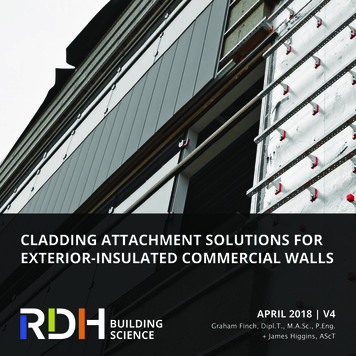
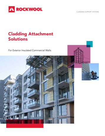
CLADDING SUPPORT SYSTEMSCladding AttachmentSolutionsFor Exterior Insulated Commercial WallsFPO
Prepared by: RDH Building Engineering Ltd.and RDH Building Sciences Inc.224 W 8th AvenueVancouver, BCV5Y 1N5Primary Author:Graham Finch, P.Eng., Dipl.T., MAScIllustrations by RDH Building Engineering Ltd. and RDHBuilding Sciences Inc. unless otherwise noted.DISCLAIMER: RDH Building Engineering Ltd. and RDH Building Sciences Inc.and ROCKWOOL Inc. have exercised due care to ensure that the data andinformation contained in this document is accurate. However, this document isfor general reference use only. Specific end use applications vary widely as todesign, materials, and environments. Thus, what is appropriate in any specificend use application is a determination that must be made independently bythe experienced engineer in their own professional judgment. RDH BuildingEngineering Ltd. and RDH Building Sciences Inc. and ROCKWOOL fullydisclaim any liability for any of the content contained herein whether suchliability be premised on a theory of contract, tort, or otherwise.ROCKWOOL Group2
Table of ContentsCladding Attachment Solutions For Exterior Insulated Commercial Walls. 4Energy Codes & Exterior Insulation. 5Requirements For Cladding Attachment. 5Cladding Attachment Systems. 6Continuous Framing. 6Vertical Z-Girts. 6Horizontal Z-Girts. 7Crossing Z-Girts. 7Clip And Rail Systems. 8Galvanized Steel Clips. 8Stainless Steel Clips. 9Thermally Isolated Galvanized Clips. 10Fiberglass Clips. 10Long Screws through Insulation. 11Masonry Ties . 12Engineered Anchors & Other Systems. 12Summary Thermal Comparison Of Systems. 13Other Considerations. 14Summary. 15ROCKWOOL Group3
Cladding Attachment Solutionsfor Exterior Insulated Commercial WallsThe use of exterior insulation installed outboard of wallsheathing is becoming increasingly common acrossNorth America to meet new energy code requirements.Commonly referred to as exterior insulation, thisinsulation is installed continuously on the outside of theprimary structure and is typically more thermally efficientthan insulation placed between studs or inboard ofthe structural system, provided that thermally efficientcladding attachments are used. Exterior insulation alsohas significant benefits for durability and thermal comfortas well. As a result, greater attention is being paid tothe design of thermally efficient structural attachmentsystems, and several proprietary systems have beenintroduced into the market in recent years to meetthis demand. Cladding attachment options includecontinuous girts, intermittent clip and rail systems, longscrews, masonry ties, and other engineered sulatedStandard approaches to insulating steel-framed wallassemblies, referred to as exterior insulated, splitinsulated and interior insulated depending on theplacement of insulation.The challenge designers and contractors face is selectingand evaluating an appropriate cladding attachmentstrategy for their project and understanding theimplications these decisions have on effective thermalperformance, installation methods, sequencing, andsystem costs.This bulletin clarifies and provides guidance regardingdifferent cladding attachment systems through exteriorinsulation for commercial wall applications.Thermal infrared image showing a cladding with thermally inefficient continuousvertical Z-girt cladding support system to left side of wall versus thermally efficientlow-conductivity clip and rail cladding support system to right side. The insulationwithin the continuous girts is less than 25% effective (about R-4 for 4” of mineralwool insulation), whereas the insulation between the intermittent clips is over 80%effective (about R-13 for 4” of mineral wool insulation) – significantly improving thethermal performance of the wall for the same construction cost.ROCKWOOL Group4
Energy Codes &Exterior InsulationThere are various energy codes and standards in forceacross North America for commercial buildings. The twomost widely applicable energy codes are the InternationalEnergy Conservation Code (IECC) in the United States,and the National Energy Code for Buildings (NECB) inCanada. The most commonly referenced energy standardis ASHRAE Standard 90.1, which is referenced by buildingand energy codes in the majority of American states andCanadian provinces. Different versions and adaptations ofthese standards and codes are in effect in the provincesand states.While different versions and adaptations of theseregulations are enforced in different jurisdictions,each requires consideration for thermal bridging andeffectiveness of installed insulation. Exterior insulationpresents an efficient and cost-effective method toprovide improved thermal performance and meetthe requirements of these regulations; however, theeffectiveness of this approach hinges on the selection ofa thermally efficient cladding attachment strategy. Thecladding attachment can be a significant thermal bridgeand reduce exterior insulation performance by as littleas 5-10% for high-performance systems, and as much as80% for poor systems.Requirements for Cladding AttachmentThere are several considerations which must be made withrespect to choosing a type of exterior insulation and claddingattachment strategy for a building. These typically includeat a minimum: Cladding weight & gravity loads Wind loads Seismic loads B ack-up wall construction (wood, concrete, concrete block,or steel framing etc.) A ttachment point back into the structure (through studs,sheathing, or slab edge) Accommodation of dimensional tolerance Allowable wall thicknessThe design of the cladding attachment system will typicallybe performed by a structural or façade engineer working forthe architect or cladding manufacturer. Many cladding supportsystems have been pre-engineered and designed using loadtables developed by the manufacturer.It is important that the cladding support designer understandsthe requirements of the project, including the thermalrequirement, so that the system and spacing of supports canbe optimized to make the best use of the exterior insulation.Various options exist, and will be selected based on a number offactors as discussed here. Thickness of exterior insulation Use of rigid, semi-rigid or spray-applied insulationo Ability to fasten cladding supports directly throughthe face of rigid insulation boardso Ability to fit semi-rigid or sprayed insulation tightlyarounddiscrete supports and ease of installation E ffective R-value target and tolerable thermalefficiency loss from supports O rientation and required attachment location forcladding system (panel, vertical, horizontal) Details for attachment of cladding at corners,returns and penetrations Combustibility requirementsDiscrete clip and railtype cladding supportwith semi-rigidinsulation placedbetween clip supportsinboard of thecontinuous vertical rail.Cladding attached backto vertical rails onexteriorof insulation.ROCKWOOL Group5Long screws throughrigid insulation utlizingcontinuous verticalstrapping to createa truss claddingsupport system.Cladding attached tostrapping on exteriorof insulation.Masonry ties withsemi-rigid insulation.The tie supports hereprovide only lateralresistance support,not gravity load(supported at thebase of the veneer).
Cladding Attachment SystemsThere are numerous generic and proprietary claddingsupport systems designed for use with exteriorinsulation available on the market today, and manydifferent materials are used to make these systemsincluding galvanized steel, stainless steel, aluminum,fiberglass, and plastic. While each system is different,the approaches can generally be classified as:continuous framing, intermittent clip and rail, longfasteners and masonry or other engineered systems.Systems are available to accommodate a wide rangeof claddings for buildings of all heights and exposures.Typically the heavier the cladding or extreme thewind load the tighter the spacing of the supports – atcompromise to the effective thermal performance. Thebest system is one that is optimized structurally andthermally for the cladding support needs of the specificproject.An overview of ten different cladding support systemsis provided in the sections below. For each of thesystems a relative cost ( - ), thermal efficiency (e.g.percent effectiveness of the exterior insulation), andease of installation ranking is provided. Within all ofthe systems, semi-rigid ROCKWOOL CAVITYROCK istypically appropriate except where noted. Where a morerigid insulation is required, such as where the screwsthrough insulation cladding support system is used orin an application where a more rigid board is preferred,ROCKWOOL COMFORTBOARD is recommended. Vertical Z-GirtsRELATIVE COST THERMAL EFFICIENCYCONSTRUCTABILITY20-40%This cladding attachment consists of continuousgalvanized steel framing members, typically 18 to 20gauge Z-girt or C-channel profiles attached verticallyto the back-up wall. Typically girts are spaced to lineup with stud framing behind (every 16” to 24” o.c.).Cladding systems are attached directly to the outerflange of the Z-girts. Where vertically oriented claddingis used, additional horizontal sub-girts may be appliedto the exterior of the verticals.Vertical Z-girts are not a thermally efficient claddingsystem and are not recommended in typical applicationsdue to the excessive amount of thermal bridging.Exterior insulation installed between vertical Z-girtsis degraded significantly and is only 20-40% effectivefor typical applications. While thermal breaks at thesheathing level can be beneficial, the insulation is stilllargely bridged, making the improvement mostly tosurface temperature rather than U-value. In terms ofprescriptive code compliance, it is very difficult to meeteffective R-value requirements with this system. All of the cladding systems can be installed withwood, steel stud, or concrete/concrete block back-upwalls, with most systems lending themselves betterto commercial construction rather than residentialpractices.Continuous FramingContinuous girt cladding support systems are thepredecessors to the more thermally efficient clip andrail systems that have been developed in the past fewyears. While continuous framing systems do not performnearly as well thermally, they are still used in someapplications.Vertical Z-girt over steel stud wall assembly. Girts are fastened to studs behindat every 16” o.c. resulting in significant thermal bridging through the exteriorinsulation.ROCKWOOL Group6
Horizontal Z-GirtsRELATIVE COST Crossing Z-GirtsTHERMAL EFFICIENCYCONSTRUCTABILITY30-50%This cladding attachment consists of continuousgalvanized steel framing members, typically 18 to 20gauge Z-girt profiles attached horizontally to steel studsor a concrete back-up wall. Typically girts are attachedto the back-up wall every 24” to 48” o.c. depending oncladding loads. Cladding systems are attached directly tothe outer flange of the girts. Where horizontally orientedcladding is used, additional vertical sub-girts may beapplied to the exterior of the horizontals.RELATIVE COST THERMAL EFFICIENCYCONSTRUCTABILITY40-60%This cladding attachment consists of two continuousgalvanized steel framing members, typically 18 to 20gauge Z-girt profiles attached in a crossing pattern tosteel studs or a concrete back-up wall. Typically girts arespaced every 16” to 24” o.c. depending on the backup framing and cladding loads. Cladding systems areattached directly to the outer flange of the exterior girts.Crossing Z-girts are not a very thermally efficient claddingsystem and not recommended in typical applicationsdue to the excessive amount of thermal bridging.Horizontal Z-girts are not a thermally efficient claddingsystem and not recommended in typical applications due Exterior insulation installed between crossing Z-girtsis degraded significantly even though the attachmentto the excessive amount of thermal bridging. Exteriorinsulation installed between horizontal Z-girts is degraded occurs intermittently and only 40-60% effective forsignificantly and only 30-50% effective for typical exterior typical exterior insulation applications. This system caninsulation applications. This is only slightly improved from be improved slightly (less than 5%) with the use of lowvertical Z-girts as less steel bridges the exterior insulation conductivity isolation thermal breaks/washers betweenframing and back-up wall, or between the crossing girts.(i.e. 24” o.c. spacing vs 16” o.c.).Crossing Z-girt assembly consisting of horizontal and vertical Z-girts attached atcrossing points.Horizontal Z-girts over a steel stud wall assembly. Girts are fastened every36” here to reduce the thermal bridging.Crossing Z-girt cladding support system with custom punched vertical Z-girt profiles used to retain ROCKWOOL CAVITYROCK insulation.ROCKWOOL Group7
Clip and Rail SystemsClip and rail systems are becoming a popular approachfor a more thermally efficient cladding support systemand can support all types of cladding. This includesboard and lap cladding that is installed using standardnail/screw fasteners, stucco/adhered veneers, stoneveneers, and a wide range of metal, glass, andcomposite cladding systems each with unique supportconditions.Clip and rail systems consist of vertical or horizontalgirts (rails) attached to intermittent clips which are thenattached back to the structure through the exteriorinsulation. Typically only the clips penetrate the exteriorinsulation; however, in some designs, the web of therail may also cut through part of the insulation. In such acase, the web degrades the thermal performance of thesystem similar to the continuous vertical/horizontal girtsystems and should be avoided as much as possible.The rails are typically made from galvanized steel Z-girtor hat-channel sections or aluminum extrusions. Theclips are made from a range of materials includinggalvanized steel, stainless steel, aluminum, fiberglass,plastic or some combination of these materials together.The less conductive the clip material and the fastenersthat penetrate the insulation, the more thermallyefficient the system will be. This is why stainless steelor fiberglass systems perform better than galvanizedsteel or aluminum, and why stainless steel fasteners maybe beneficial compared to galvanized steel fasteners.The strategy with all clip systems is to maximize thespacing and use as few clips as possible while meetingthe structural requirements. This maximum clip spacingis typically governed by the cladding wind loads andstiffness of the rail section. Low conductivity clips arealso beneficial since inevitably more clips are needed atdetail locations. While this is not necessarily accountedfor in current energy codes, it will likely become aconsideration in the future, as thermal bridgingat such locations becomes a central concern.ROCKWOOL Group8
Galvanized Steel ClipsRELATIVE COST Stainless Steel ClipsTHERMAL EFFICIENCYCONSTRUCTABILITY50-75%This clip and rail support system utilizes intermittentgeneric metal clips made of cold formed galvanized steel.The clips typically take the form of 16-20 gauge Z-girts,C-channels, or L-angles in 4-8” lengths with depth tosuit the insulation and/or cladding cavity. Dimensionaladjustability can come from the use of separated back toback L-brackets screwed together as they are installedor the use of plastic or metal shims installed on the wallbehind the clips. The clips are attached to vertical orhorizontal rails which are most often Z-girts, hat-channelsor C-channels. Cladding is attached directly to these railswith short screws. The rail sections should ideally notpenetrate the insulation as this will degrade the effectivethermal performance of the system.The thermal efficiency of a clip and rail system withgalvanized steel is predominantly affected by the spacing,gauge, and length of the clips. Typically clips are spacedevery 16” horizontally and 24-48” vertically dependingon the cladding loads. Given the variables, the thermalefficiency of galvanized steel clip and rail systems canrange considerably from less than 50% to as high as 75%.RELATIVE COST THERMAL EFFICIENCY65-85%This clip and rail system is very similar to the galvanizedsteel clip option described previously, but instead theclips are made of stainless steel profiles (rails remain asgalvanized steel). Stainless steel is more than four timesless conductive than galvanized steel, and therefore morethermally efficient. Because of the lower conductivity ofthe clips, this system performs quite well with thermalefficiencies in the 65 to 85% range depending on spacingand clip dimensions.In terms of installation, pre-drilling the stainlesscomponents can help with fastening onsite. In additionto the generic options available, there are a fewmanufacturers who now produce and sell stainless steelclips including a pre-drilled back to back L-bracketallowing for site adjustability.In addition to the generic options available, thereare some manufacturers who now produce pre-madeengineered galvanized steel clips.Intermittent stainless steel clips with vertical girts.Intermittent galvanized steel clips with vertical girts.CONSTRUCTABILITYGeneric adjustableback to backL-angle clips.ROCKWOOL Group9
Thermally Isolated Galvanized ClipsRELATIVE COST THERMAL EFFICIENCYFiberglass ClipsCONSTRUCTABILITY60-90%This clip and rail system consists of proprietary heaviergauge galvanized steel clips with 1/8” to 1/2” plasticpads/washers installed between the clip and backupstructure. Plastic washers may also be used at fastenersto reduce the heat transfer. Vertical or horizontal girtsare attached to the clips using screws and the claddingis attached to these girts. There are currently multiplemanufacturers of similar products in the market withvarying thermal and structural performance.In terms of thermal performance, the plastic componentsreduce the heat flow through the clip to performancelevels similar to stainless steel clip systems. Again the keyto maximizing the thermal performance of this systemis to reduce the number of clips required. The thermalperformance of this system varies between 60% and 90%depending on the manufacturer’s details and spacing.RELATIVE COST THERMAL EFFICIENCYCONSTRUCTABILITY70-95%This clip and rail system utilizes low-conductivityfiberglass clips. Fiberglass is approximately 200 timesless conductive than galvanized steel and improves thethermal performance significantly. One or two long screws(galvanized or stainless steel) through each clip connectthe vertical or horizontal galvanized steel rail through theshear block clip back to the structure.With this system, Z-girts or hat-channels are used as thevertical or horizontal rail elements entirely on the exteriorof the insulation. The fiberglass clips are often pre-clippedto the metal girts and then screwed to the wall as oneelement, speeding up installation time.There are two variants of the fiberglass clip in the marketwith varying structural, fire, and thermal performancecharacteristics. The thermal performance of a fiberglassclip and rail system is heavily dependent on the spacingof the clips and type of screw fasteners used (galvanizedvs stainless) and ranges from 70% with tightly spaced clipsfor heavier claddings to over 90% with optimally spacedclips for lighter claddings.Thermally isolated galvanized steel clip attached to wall with screws throughplastic isolation pad.Fiberglass clips withvertical Z-girt attachedwith screw fastenersthrough the fiberglassclips into the back-upwall.Fiberglass clips (spacers)attached to wall withscrews, horizontal Z-girtsattached to clips withscrews.Additional examples of thermally isolated galvanized steel clips wherelow-conductivity pads are used to reduce the heat flow through each clip. Notethat the best performance arises when the continuous girts attached to the clipsare entirely outboard of the insulation and do not cut through it.ROCKWOOL Group10
Long Screws through InsulationRELATIVE COST THERMAL EFFICIENCYCONSTRUCTABILITY75-95%This cladding attachment system utilizes long fastenersthat connect girts or strapping on the exterior of rigidinsulation (ROCKWOOL COMFORTBOARD ) directly intothe structure. Semi-rigid insulation is not recommendedas it is too compressible in this application. The combination of the continuous exterior strapping/girts, long fasteners, and rigid insulation creates a trusssystem to support lightweight to medium weight claddingsystems. Deflection is limited by the truss action and canbe further limited by installation of fasteners screwedin upwards at an angle through the insulation. The onlythermal bridges through the exterior insulation are thelong galvanized or stainless steel screws. Claddings areattached directly to steel girts or wood strapping onthe exterior surface of the insulation. Typically verticalstrapping is used as it provides a vertical cavity fordrainage and ventilation behind the cladding alongwith greater load carrying capacity; however, horizontalstrapping can also be used for some claddings.Long screws through vertical wood strapping and rigid ROCKWOOL COMFORTBOARD insulation on a multi-family residential project.Typically 18 to 20 gauge hat-channel profiles forgalvanized steel girts or minimum ¾” plywood ordimensional lumber are used for the exterior girts/strapping. Typically the fasteners consist of #10-#14steel screws every 12-16” o.c. in lengths to connect theexterior girt/strapping to the backup structure (studs,sheathing, or concrete). Typically the required screwlength can be estimated by the thickness of exteriorinsulation plus 1 ½” - 2”.One challenge installers face with this system is thepositive connection of the screw fasteners back to thestructure. With wood framing this can be achieved byeither hitting the studs or designing the plywood or OSBsheathing for the required pull-out resistance. With steelstuds this requires careful alignment to hit but not stripthe studs. With concrete and concrete block back-up, thisrequires special concrete or masonry fasteners.Long screws through horizontal metal hat tracks and rigid ROCKWOOL COMFORTBOARD insulation on a commercial building project.The thermal performance of this system depends on theback-up wall, type of fastener and fastener spacing. Fortypical conditions, the insulation effectiveness will be inthe range of 75% to 85% for galvanized screws in steel/concrete backup, and up to 90-95% for stainless steelscrews in wood-frame backup.ROCKWOOL Group11
Engineered Anchors & Other SystemsMasonry TiesRELATIVE COST THERMAL EFFICIENCYCONSTRUCTABILITY40-90%Masonry veneer systems are supported by gravity bearingsupports (shelf angles, corbels, etc.) and intermittent tiesfor lateral and out of plane support. Masonry ties bridgethe exterior insulation similar to other cladding supportsand therefore are thermal bridges. There are a range ofproprietary and generic masonry tie systems available inthe market and the thermal efficiency ranges from fair toexcellent (approximately 40 to 90%) depending on thenumber of ties and type of metal used.In addition to the various cladding attachment systemspresented in this bulletin, there exist many opportunitiesfor engineered approaches and adaptations of existingsystems.Stone veneer systems have long used heavy gaugeengineered clips to structurally support heavy claddingsand have adapted dimensions to support through afew inches of exterior insulation. Many of these heaviergauge steel anchors will be large thermal bridges, andthermal modeling is suggested to assess opportunitiesfor improvement, including spacing optimization orincorporation of thermal break materials.An example of a heavy-duty engineered cladding anchorsupport system is shown below where large steel plateshave been bolted into the concrete structure at 10 to 12’spacing. An aluminum rail system spans over top of thesteel plates to support the panel cladding system.Examples of masonry ties installed through ROCKWOOL CAVITYROCK insulation.Example of heavy-duty engineered anchor consisting of largewelded steel plates and vertical rail system.Examples of alternate masonry ties installed through ROCKWOOL CAVITYROCK insulation.Cladding manufacturers are constantly developing newand improved support systems. The list of availablecladding support systems from that covered withinthis bulletin will continue to grow and modifications ofexisting systems will become more commonplace. Suchexamples include the use of discrete fiberglass clips oraluminum and plastic clips to support composite metalpanels (below).Examples of thermally improved discrete cladding supports forcomposite metal panels.ROCKWOOL Group12
Summary ThermalComparison of SystemsTo summarize the thermal performance of the variouscladding support strategies presented, the range ofthermal effectiveness of the exterior insulation is shownbelow. These percentages can be multiplied by theR-value of the exterior insulation and added to the backup wall R-value to determine an approximate overalleffective R-value for the wall assembly.This same information can also be used to help selectan appropriate thickness of ROCKWOOL CAVITYROCKinsulation over an uninsulated 3 5/8” steel studframe back-up wall in the chart below. For example,to get to an effective R-20 with this back-up wall, 6”of CAVITYROCK insulation is required with severaldifferent cladding support systems. The range in values provided encompasses typicalsupport structure spacing when attached to steel stud,concrete, and wood back-up walls for a range of typicalcladdings. The percent insulation effectiveness alsodecreases with thicker amounts of exterior insulation.The values were determined using calibrated threedimensional thermal modeling software. Each of thesystems was modeled using the same set of assumptions,boundary conditions, and material property inputs.Manufacturers will also be able to provide their ownpublished data.Uninsulated 3 5/8” steel stud wall with exterior insulation and cladding attachmentsystem.Continuous Vertical Z-GirtContinuous Horizontal Z-GirtAluminum T-Clip35Isolated Galvanized ClipStainless Steel ClipFiberglass ClipGalvanized ScrewsPercent Insulation nless Steel ScrewsEffective R-Value (ft2 F hr/Btu)Intermittent Galvanized Clip3025201510502"4"6"Insulation Thickness of ROCKWOOL CAVITYROCK Over Empty 3 5/8” Steel Stud Back-up WallStainless Steel Screws - 16" x 12"Galvanized Screws - 16" x 12"Fiberglass Clip - 16" x 24"Stainless Steel Clip - 16" x 24"Isolated Galvanized Clip - 16" x 24"Intermittent Galvanized Clip - 16" x 24"Continuous Horizontal Z-Girt - 24" OCContinuous Vertical Z-Girt - 16" OCROCKWOOL Group138"
Other ConsiderationsIn addition to the cladding supports, mechanicalattachments are also needed to support and hold theexterior insulation in place where not provided by thecladding support system. These insulation fasteners areintended to retain the insulation tight to the back-upwall and the cladding supports as gaps between boardsof insulation or behind the insulation will degrade thethermal performance, especially if the insulation becomesdislodged behind the cladding in-service.These fasteners are used throughout the wall area, andi
gauge Z-girt profiles attached in a crossing pattern to steel studs or a concrete back-up wall. Typically girts are spaced every 16" to 24" o.c. depending on the back-up framing and cladding loads. Cladding systems are attached directly to the outer flange of the exterior girts. Crossing Z-girts are not a very thermally efficient cladding