Transcription
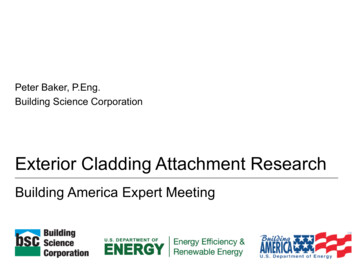
11/17/2017Overview Building Insulation Retrofit Strategies Exterior Insulation Approaches– Insulation and Separate Cladding– Exterior Insulation and Finish System (EIFS)– Insulated Metal PanelsPeter BakerExterior Insulation:Strategies and Cladding Attachment Cladding Attachment ResearchNovember 16, 2017Exterior Insulation and Cladding AttachmentInsulation Retrofit Existing buildings are often un‐insulated/poorlyinsulated Insulation options are:Insulation Retrofit OptionsExterior Insulation and Cladding Attachment– Cavity fill– Interior insulation– Exterior insulationExterior Insulation and Cladding Attachment1
11/17/2017Cavity Fill Insulation Cavity fill insulation is most common retrofit –but has limitationsInterior Insulation Interior insulation retrofit concerns– Continuity of insulation (partition walls, floors, etc.)– Loss of floor space– Occupant disruption– 4” cavity for older wood frame– ¾” cavity for mass masonry Desirable if exterior appearance isneeded/wanted to be maintained Often the best approach for historic buildings Not ideal from a building physics perspectiveExterior Insulation and Cladding AttachmentExterior Insulation and Cladding AttachmentExterior Insulation Exterior insulation retrofit– Ideal from a building physics perspective– Can be completed with less disruption to occupants– May come at a higher cost than other approachesExterior Insulation New approach!New approach?Not a new approach Pesky Canadians Benefits discussed in Canadian Building Digestsproduced by the National Research Council ofCanada in the 1960’sExterior Insulation and Cladding AttachmentExterior Insulation and Cladding Attachment2
11/17/2017Exterior InsulationExterior Insulation CBD 44 (W.P. Brown, A.G. Wilson) – Published in1963 The “Perfect” Wall“Application of insulation over the entire exterior of a wallprovides an ideal solution to the problems presented bythermal bridges.” Increase overall thermalperformance Minimize thermal bridges Minimize potentialfor air leakagecondensation Improve air tightness? Improve rainwatermanagement?“It should be stressed that many of the thermal bridges occurringin present‐day construction can be avoided, or their effectsminimized, if they are recognized in the early stages of design.”Exterior Insulation and Cladding Attachment1980s ON – a “weird” builderExterior Insulation and Cladding AttachmentExterior Insulation and Cladding Attachment1990s ON – a “good” builderExterior Insulation and Cladding Attachment3
11/17/20172000s ON – a “typical” builderExterior Insulation ApproachesExterior Insulation and Cladding AttachmentExterior Insulation Approaches Insulation and cladding(discrete components)Exterior Insulation and Cladding AttachmentExterior Insulation and Cladding AttachmentExterior Insulation Approaches Insulation and cladding(discrete components) Exterior Insulation and FinishSystem (EIFS)Exterior Insulation and Cladding Attachment4
11/17/2017Exterior Insulation Approaches Insulation and cladding(discrete components) Exterior Insulation and FinishSystem (EIFS) Insulated Metal Panels (IMP)– Used as a complete enclosureExterior Insulation and Cladding AttachmentBrick VeneerExterior Insulation Approaches Insulation and cladding(discrete components) Exterior Insulation and FinishSystem (EIFS) Insulated Metal Panels (IMP)– Used as a complete enclosure– Used as an insulated claddingExterior Insulation and Cladding AttachmentBrick Veneer Brick veneer has some of the longest historywith exterior insulation– Long history more common– More common less questions Not always well doneExterior Insulation and Cladding AttachmentExterior Insulation and Cladding Attachment5
11/17/2017Brick VeneerBrick VeneerExterior Insulation and Cladding AttachmentExterior Insulation and Cladding AttachmentBrick VeneerBrick Veneer Alternate details and support options exist Support systems for brick can be modifiedfor other building elements– Decks– Balconies– Canopies– Etc.Exterior Insulation and Cladding AttachmentExterior Insulation and Cladding Attachment6
11/17/2017Brick VeneerExterior Insulation and Cladding AttachmentOther Claddings For insulation less than 1.5” – direct attachment of claddingthough insulation back to the structure is practical For insulation greater than 2” – a secondary claddingsupport structure is often needed.Brick VeneerExterior Insulation and Cladding AttachmentOther Claddings Lighter weight claddings (metal/wood/fibercement)– Less common less experience– Less experience more questions Cladding support systems historically donepoorly Systems are getting betterExterior Insulation and Cladding AttachmentExterior Insulation and Cladding Attachment7
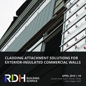
11/17/2017Other CladdingsOther Claddings Single “z‐furring”– Poor thermal performance (steel stud wall onthe exterior – why bother?)Exterior Insulation and Cladding AttachmentOther Claddings Single “z‐furring” Double “z‐furring”– Can be made to function reasonably wellprovided that two layers of insulation are used.– Often designed with first layer bridginginsulation and second layer creating a gapbehind the cladding single “z‐furring”Exterior Insulation and Cladding AttachmentExterior Insulation and Cladding AttachmentOther Claddings Single “z‐furring” Double “z‐furring”Exterior Insulation and Cladding Attachment8
11/17/2017Other CladdingsOther Claddings Single “z‐furring” Double “z‐furring” Clip and “z‐furring” orhat channel– Metal clip– Fiberglass clipExterior Insulation and Cladding AttachmentOther CladdingsExterior Insulation and Cladding AttachmentOther Claddings Single “z‐furring” Double “z‐furring” Clip and “z‐furring” or hatchannel– Metal clip– Fiberglass clip Attach furring directly backto structure throughinsulationExterior Insulation and Cladding AttachmentExterior Insulation and Cladding Attachment9
11/17/2017EIFS Exterior Insulation and FinishSystem (EIFS)– Lightweight– Cost effective– Water managed Minimal Thermal Bridging R‐4 per inch System has a tainted historyExterior Insulation and Cladding AttachmentEIFSEIFS Commonlyinstalled usingadhesive The adhesivecan also formthe drainagegap in watermanagedsystemsExterior Insulation and Cladding AttachmentInsulated Metal Panels Insulated Metal Panels (IMP)– Lightweight– Moderate cost– Water managed Minimal Thermal Bridging R‐7.5 per inch Can be an excellent enclosuresystem Requires some consideration forretrofit applicationsExterior Insulation and Cladding AttachmentExterior Insulation and Cladding Attachment10
11/17/2017Insulated Metal Panels Can be used as both acomplete enclosure systemInsulated Metal Panels Can be used as both acomplete enclosure system Can also be used as aninsulated cladding systemExterior Insulation and Cladding AttachmentInsulated Metal Panels Attachment often to metal hatchannel or z‐furring– In retrofit applications out ofplane walls can requirespecial adjustable systems orshimsExterior Insulation and Cladding AttachmentExterior Insulation and Cladding AttachmentInsulated Metal Panels IMP as a complete enclosuresystem– Provides all enclosurefunctions into a single system– System design as intended bypanel manufacturesExterior Insulation and Cladding Attachment11
11/17/2017Insulated Metal Panels IMP as a complete enclosuresystem– May require special detailingfor compartmentalization atfloors or partition walls,particularly in retrofitapplicationsExterior Insulation and Cladding AttachmentInsulated Metal Panels IMP as an insulated claddingsystem– Provides thermal insulationand cladding– Rain water management andair tightness are provided byother elements– Modification tomanufacturers intendeddesignExterior Insulation and Cladding AttachmentInsulated Metal Panels (Retrofits) IMP as an insulated cladding system– Need to fill space between thepanel and back up wall toprevent air by‐pass of theinsulation– Can simplify certain details suchas interfaces at balconies, lowerroofs, and compartmentalization– More in line with commonconstruction detailingExterior Insulation and Cladding AttachmentCladding Support System:Direct Attachment ThroughInsulationExterior Insulation and Cladding Attachment12
11/17/2017BackgroundBackground Industry trend to using exterior rigid insulation– Increased thermal value– Condensation resistance– Increased air tightness (possibly)– Increased rainwater management (possibly) Need to develop a means to attach cladding over thick layers ofexterior insulation that can meet the following requirements:– Provides good thermal performance– Low cost– Easy to construct/install (low cost)Exterior Insulation and Cladding Attachment Current pneumatic nailers have maximum fastener lengths of 3”to 3.5” which limits insulation thicknesses to 1.5” max– 3.5” fastener, ¼” to ½” siding, 1 ½” embedment (3.5‐0.5‐1.5 1.5” max insulation) Therefore, for insulation greater than 1.5” direct attachment ofcladding though the insulation back to the structure is often notpracticalExterior Insulation and Cladding AttachmentDirect Attachment Through InsulationDirect Attachment Through InsulationMasonryStructureWoodstructure2x4 framingattached tosurface ofmasonry2” to 4” ofexterior rigidinsulation2” to 4” ofexterior rigidinsulation1x3 woodfurring strips1x3 woodfurring stripsExterior Insulation and Cladding AttachmentExterior Insulation and Cladding Attachment13
11/17/2017Direct Attachment Through Insulation Lots of practical experience with this approach for lightweightcladding systems over thick layers of insulation (severaldecades). Approach has demonstrated very good long term performance High resistance from industry– Compression resistance of insulation– Long term creep“Myths” “Does the insulation crush under load?” YES! Loading a system until failure (500lbs to 1000lbs ormore per screw fastener) will crush most rigidinsulations .Unfortunately that is the wrong questionExterior Insulation and Cladding AttachmentExterior Insulation and Cladding Attachment“Myths” “Does the insulation crush under a load similar towhat will be imposed on it in a cladding supportapplication?” The answer is no!.Context is importantExterior Insulation and Cladding AttachmentTypical Loads Typical cladding weights (psf)lowhighVinyl0.61.0wood1.01.5fiber cement3.05.0stucco10.012.0adhered stone veneers17.025.0Exterior Insulation and Cladding Attachment14
11/17/2017Typical LoadsDesign Criteria Typical weights per fastener (lbs)fastener spacing (in)16" x 16" 16" x 24"24" x 24"area/fastener nt8.913.320.0stucco21.332.048.0adhered stone veneers44.466.7100.0Exterior Insulation and Cladding AttachmentBSC Cladding Attachment Research Began in 2011 Looking to expand onprevious research Broken into two sections: mechanics of thecladding attachmentsystem long termenvironmentalexposureExterior Insulation and Cladding Attachment Acceptable deflection not ultimate capacity governs What is acceptable deflection?– Movement a cladding system can accommodatewithout physical damage or exceeding aesthetictolerances Proposed limit of 1/16” vertical deflectionExterior Insulation and Cladding AttachmentFull System Laboratory Tests Looked at initial responsefull system capacity aswell as long termsustained loading Used full scale samples tolimit variations in fastenerinstallationExterior Insulation and Cladding Attachment15
11/17/2017Full System Laboratory TestsFull System Laboratory Tests Results Insulation type not asignificant influence onsystem capacity System capacity is afunction of the number offasteners used High measured capacitiesand stable performanceunder controlledenvironmental conditionsTotal Load vs. Vertical Displacement of Furring Strip over 4" of PIC Insulation10009508” oc (13 Fasteners)90085016” oc (7 Fasteners)80024” oc (5 Fasteners)750700650Load 10.230.24deflection (in)4" Thermax‐ 24" OCExterior Insulation and Cladding Attachment4" Thermax‐ 16" OC4" Thermax‐ 8" OCExterior Insulation and Cladding AttachmentFull System Laboratory TestsBSC Cladding Attachment Research System MechanicsPer Fastener Load vs. Vertical Displacement of Furring Strip over 4" PIC Insulation757065605550Load (lbs per ction (in)4" Thermax‐ 24" OC4" Thermax‐ 16" OC4" Thermax‐ 8" OCExterior Insulation and Cladding AttachmentExterior Insulation and Cladding Attachment16
11/17/2017Screw BendingScrew Bending Cantilever Double Bending Screw Shaft Bearing Double bending resistance was significantlyhigher ( 4 times) than simple cantilever. Double bending is more in line with theexpected performance of the assemblies but stillonly accounted for a fraction of the totalmeasured system capacity Screw shaft bearing on the insulation was hardto quantify, but appeared to be significant inshort term (initial response) testsExterior Insulation and Cladding AttachmentExterior Insulation and Cladding AttachmentScrew BendingSystem Friction Compression Forces Coefficients of FrictionLoad vs. displacement for #10 wood screws under simple cantilever anddouble bending1615141312Load per fastener (lbf)11109876y 65.263x5432y 13.223x1000.0150.030.045#10 Cantilever0.060.0750.09#10 Double Bending0.105 0.12 0.135Deflection (inches)0.150.165Linear (#10 Cantilever)0.180.1950.210.2250.24Linear (#10 Double Bending)Exterior Insulation and Cladding AttachmentExterior Insulation and Cladding Attachment17
11/17/2017System Friction Function of fastener tensionand insulation compression Measured insulationcompression properties Difficult to measure directly Fastener bending present Hard to create a“frictionless” system May have a more significantcontribution in the form ofadditional friction thancompression resistanceExterior Insulation and Cladding AttachmentExterior Insulation and Cladding AttachmentExterior Exposure TestingExterior Exposure TestingVertical deflection movement of a wood furring strip (loaded to 8lbs/fastener) over time in an exposedenvironment Looked at long termmovement of systemsunder sustained loads inan exposed tion (in)0.330.300.280.25601/4"0.230.200.1540MF and PIC assembliesloaded at this e (F) / Relative Humidity (%) Compression Forces were measured at around150lbf/fastener to drive a #10 wood screw flushwith face of furring Coefficients of frictions were typically around 0.25 Compression forces were also measured to dropoff over time (around 20% to 30%) after initialloading and be highly sensitive to environmentalconditionsCompression 7/1/128/31/1210/31/1212/31/12XPSExterior Insulation and Cladding Attachment3/2/135/2/137/2/13‐209/1/13DateMF installed but not loaded during this timeEPSMFPICTemperatureRHExterior Insulation and Cladding Attachment18
11/17/2017Exterior Exposure TestingExterior Exposure TestingVertical deflection movement of a wood furring strip (loaded to 30lbs/fastener) over time in an exposedenvironmentVertical deflection movement of a wood furring strip (loaded to 15lbs/fastener) over time in an .430.400.4080600.281/4"0.250.230.2040MF and PIC assembliesloaded at this 300.280.25601/4"0.230.200.1540MF and PIC assembliesloaded at this e (F) / Relative Humidity (%)0.300.35Deflection (in)Deflection (in)0.33Temperature (F) / Relative Humidity /2/137/2/13‐209/1/13DateMF installed but not loaded during this .0210‐0.02500/0212/0200/03012/03Temperature and Relative Humidity ( C, atureRHConclusions (System Mechanics)1000.0253/2/13DateExterior Insulation and Cladding AttachmentDiurnal Movement of the Furring Strip with Respect to the Stud Framing(recorded over a three day period)12/018/31/12XPSRHExterior Exposure Testing00/01‐0.107/1/12MF installed but not loaded during this timeExterior Insulation and Cladding ve Deflection (in)800.380.38‐0.05100 Initial load response measurements are on the order of 40to 50lbf/fastener at 1/16” deflection and 4” of insulation Insulation type does not appear to be overly significant Capacity is a function of the number of fasteners used. Capacity would be expected to increase for less insulationdue to higher fastener component at a smaller cantilever Friction component is significant, but highly variable due toinitial clamping magnitudes and thermal expansion andcontraction of materials Compression strut component is present, however themagnitude of the impact is difficult to quantify.Time and Date (hours/day)Deflection‐T‐Corrected (in)Ambient Air Temperature ( F)Relative Humidity (%)Exterior Insulation and Cladding AttachmentExterior Insulation and Cladding Attachment19
11/17/2017Conclusions (Long Term Exposure) System creep was apparent at high per fastener sustainedloading (30lbs/fastener) At low per fastener loads (8lbs/fastener) the systemdemonstrated stable performance At moderate per fastener load (15lbs/fastener) the systemdemonstrated relatively stable performance, though thereis some possible slight indication of system creepExterior Insulation and Cladding AttachmentRecommendations Based on the results of the testing it is currentlyrecommended to use a maximum load per fastener of nomore than 10lbs for up to 4” of insulationVertical fastener spacing (in) per cladding weightCladding weight(psf)16” oc Furring24” oc Furring518121096156420432532Exterior Insulation and Cladding Attachment20
Nov 16, 2017 · Exterior Insulation and Cladding Attachment Other Claddings For insulation less than 1.5” –direct attachment of cladding though insulation back to the structure is practical For insulation greater than 2” –a secondary cladding support structure is
