Transcription
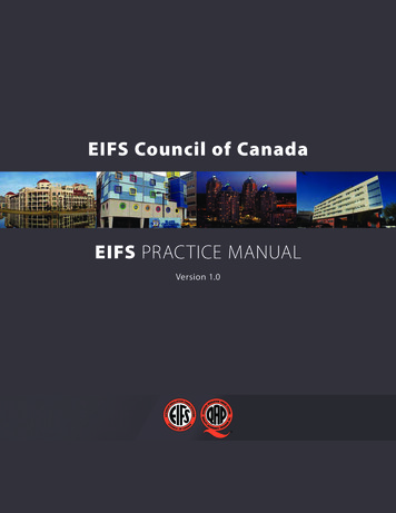
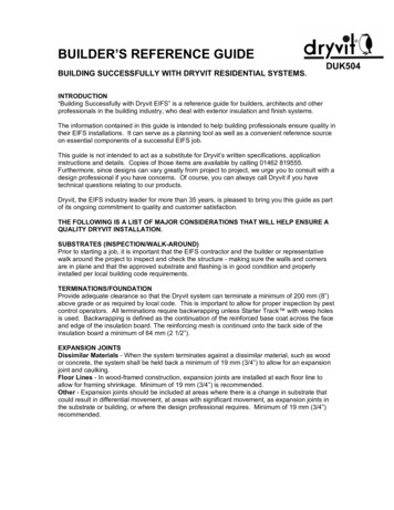
improper installation and the designprofessional for inadequate installa tion details.BACKGROUNDHistoryThe Exterior Insulation andFinish System (EIFS) was originallydeveloped in West Germany in the1960s. The original market for EIFSwas providing an insulation layer toexisting masonry structures. EIFSwas introduced in the U.S. in the1970s. U.S. manufacturers adaptedEIFS for use on new construction,including wood-framed structures.An EIFS system is comprised of fivecomponents (adhesive or mechani cal fasteners, insulation board,reinforcing mesh, base coat, andfinish coat) that were originallyintended to serve as a “barrier”cladding (see Figure 1). A successfulbarrier cladding serves as the onlyline of defense against weather anddoes not allow significant waterpenetration.LitigationProblems with water intrusionon EIFS-clad structures began surfacing inthe 1980s. To date, thousands of EIFS-cladbuildings have been the subject of litigation.While there is no single cause for damagesto EIFS-clad structures, the typical argu ments are summarized as follows: The OWNER does not know whocaused the problems. The ownerwrote checks to contractors anddesign professionals and relied onthe expertise of these individuals todeliver an adequate product, free ofdefects or damage.4 INTERFACESome cases involve more parties, whichallows more blame to be spread around.However, the purpose of this paper is not torehash the arguments described above butto identify areas of typical damage on EIFSclad structures and present practical repairoptions.Figure 1 The GENERAL CONTRACTORblames the applicator (if available)for improper installation and themanufacturer and/or design profes sional for inadequate installationdetails.The DESIGN PROFESSIONALblames the contractor and/or appli cator for improper installation andthe manufacturer for inadequateinstallation details.The MANUFACTURER blames thecontractor and/or the applicator forCurrent PracticesWhile original barrier EIFS is still inuse, many new construction projects (andmany repair projects) include “drainable”EIFS cladding. Drainable EIFS includes thesame basic component but incorporates adrainage plane and flashings to addressincidental water intrusion. The drainageplane is created using a fluted insulationboard and/or a drainage mat. All drainableEIFS cladding systems include some type ofmoisture barrier (see Figure 2). Termina tions of drainable EIFS cladding systemsinclude a weeping mechanism and flashingdetails.The installation details required fordrainable EIFS cladding are similar in con cept with details of nearly all drainage-typecladdings. While the author has not investi gated or observed significant damages asso ciated with drainable EIFS, the viability ofthe system is dependent on the quality ofthe installed details. The technical designconcepts of drainable EIFS appear to makesense. However, as with all building assem blies, bad construction can always void agood design.FEBRUARY 2006
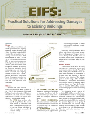
actual area of damage on most EIFS-cladstructures is relatively small.Figure 2REPAIR OR REPLACEDetermine the Extent of DamageBefore deciding to repair or replace EIFSon a damaged building, the full extent ofdamage must be determined. In most cases,the extent of damage is limited to localizedareas at wall penetrations. This is consis tent with the familiar “90/1” rule in water proofing.1 This rule suggests that 90 per cent of all water intrusion occurs in approx imately one percent of the building envelopearea. Of the numerous EIFS repairs andreplacement projects that have been docu mented by the author, this rule seems tohold true. It is very rare (never observed bythe author) that water intrusion occurs inthe field of an EIFS-clad wall with no pene trations.The survey of damages should be per formed by a qualified inspector using aprobing-type moisture meter (see Figure 3).While non-destructive moisture meters arehandy for covering large wall areas (seeFigure 4), they need to be “ground truthed”on every building elevation and may missareas that have been previously damagedbut are no longer associated with elevatedmoisture. The moisture meter probesshould be used to provide a qualitativeassessment of the condition of the underly ing wall sheathing (i.e., soft, hard, etc.). Inareas of damage, several probes should bemade to estimate the area of possiblesheathing replacement. These areas shouldtypically be enlarged (in some instances,more than 100 percent) to allow for replace ment of full sheets of wall sheathing asdescribed below. Keep in mind that theFEBRUARY 2006Building Code IssuesEIFS removal can sometimes berequired, even in the absence of damage.For instance, cases that include significantconstruction defects can dictate EIFSremoval for purposes of making repairs tounderlying components. An example of thisscenario is when the wall framing of a struc ture is not adequate to meet building code(or manufacturer-imposed) deflection crite ria when subjected to a load perpendicularto the wall. In the case of EIFS, the maxi mum allowable deflection (PM, or polymermodified system) normal to the plane of thewall is L/360.2 The maximum allowabledeflection (PB or polymer-based system)normal to the plane of the wall is L/240.3These criteria can be difficult to meet onmulti-story structures in coastal (high wind)areas. This problem can also occur whenbuilding code requirements imposed on therepair are more stringent than thoseimposed on the original construction.Another issue that tends to expandEIFS repair areas is replacement of dam aged wall sheathing. While many repairshave been performed using partial sheets ofstructural wall sheathing panels, it is theauthor’s opinion that repairs to wall sheath ing should be made using full (4' x 8') sheetswhenever possible. At a minimum, therepair panels used should match thedimensions of panels used in the originalconstruction (unless found to be defective).This opinion is based on maintaining thestructural integrity of the framing system. Ifsmaller structural panels are used, theyshould span across a minimum of three ver tical studs and include blocking at thepanel joints.Aesthetic IssuesWhile localized repairs may be adequateto address damages, complete removal maybe more practical to provide a more pleasingend result. In some cases where damagedareas are close together (i.e., a house withmany windows), the localized repairapproach would result in many patchesthat will be visible, even with the mostskilled applicator. In these cases, completeremoval and replacement of EIFS on anentire wall area may be the most practicalapproach to provide a uniform appearance.In some instances, this approach may costless than multiple localized repairs.Property Value/Stigma IssuesOwners and experts who promote totalremoval of EIFS often argue that the valueof the property will be reduced if any EIFSremains. Additionally, an argument is madethat EIFS has a stigma and will cause theowner to have a difficult time selling theproperty, even at a reduced price.First, property value and stigma issuesare beyond the author’s area of expertiseand the scope of this paper. Second, whileFigure 4Figure 3INTERFACE 5
Figure 5these arguments may be supported by otherexperts (that are typically not real estateappraisers), they seem to be of reducedvalidity in the most recent EIFS litigation,where the owners themselves purchasedthe structure long after the first EIFS litiga tion. This paper is intended to present thetechnical merits of repairing damages toEIFS-clad buildings.Therefore, no furtherdiscussion on thesetopics is provided.TYPICAL AREAS OFDAMAGE/REPAIR DETAILSRoof/WallIntersections –Typical DamageBy far, improperdetails at this locationhave the potential forcausing the mostsevere damage. Thisis particularly true inthe case of woodframe structures oftwo or more stories.The required “kickout” flashing must beinstalled in a water tight manner to pre vent water from beingdirected behind theEIFS at these loca 6 INTERFACEFigure 6tions. The absence of a proper flashingdetail can result in significant damage towall sheathing and framing located belowthe roof/wall intersection.A “kick out” detail is typically includedwith current manufacturer installationinstructions (see Figures 5 and 6). However,the importance of this detail was not recog-nized by the industry until after significantdamages were documented and litigationwas well underway. As late as 1994, detailsfrom the EIFS Industry Members Associa tion (EIMA)4 did not specifically include“kick out” flashing. However, a general ref erence was made to flashing being requiredin this area (see Figure 7).Figure 7FEBRUARY 2006
Figure 8Roof/Wall Intersections – Repair DetailsRepairing damages at roof/wall intersections typically requires theremoval of large areas of EIFS below the defective intersection. Unless thewall area is large (more than 100 square feet), it is often wise to removeand replace the EIFS on the entire wall. This will result in a uniformappearance and allow all damages to be discovered and addressed.Repair to the wall area located below the defective intersection caninclude barrier EIFS or drainable EIFS. However, consideration should begiven to any areas of the repair that would intersect adjacent EIFScladding. In particular, the designer of the repair should try to select arepair cladding that matches the thickness of the adjacent cladding.FEBRUARY 2006Figure 9INTERFACE 7
Figure 10aFigure 10bshould include aninspection of floorframing that adjoinsthe damaged wallarea.Figure 10cAdditionally, depending on which type ofcladding is selected, expansion jointsand/or flashing details may be necessary toseparate the repair area from the adjoiningwall sections. Repair of damages caused bydefective details at roof/wall intersections8 INTERFACEWindows – TypicalDamageWindows repre sent the most com mon “hot spot” on allEIFS-cladstruc tures. In fact, itcould be argued thatwindows representthe most common“hot spot” on allstructures, regard less of cladding type. This opinion is basedon the simple fact that nearly all structureshave windows and nearly all windows even tually leak.5These facts were not adequatelyaddressed by the construction industry inearly EIFS-clad structures, at least not inpublicly-available print. Fingers have beenpointed at all parties for problems associat ed with windows. Again, the purpose of thispaper is to simply identify windows as anarea of damage that may require repair. It isthe job of construction attorneys and theirexperts to assign blame for the damage.It is the author’s opinion that structuresshould be designed with the assumptionthat all windows will leak, regardless ofcladding type. For this reason, a prudentdesign professional should consider thewindow as part of the wall system andinclude proper water management detailsusing wraps, barriers, flashings, etc. asnecessary. Damages at windows are typical ly below the bottom left and right corners ofmost exposed windows (see Figure 8).Additional damages can be associated withlarger windows that consist of multiple win dow units that are ganged together.FEBRUARY 2006
Windows – Repair DetailsWindow repairs are likely to includeareas below the window unit. In commercialconstruction (where windows are often situ ated in a straight vertical column), it iseffective to begin repairs at the top of thebuilding and proceed toward the ground(see Figure 9). Depending on the extent ofdamages, removal of all EIFS located direct ly above and below the windows can be aneffective approach (see Figures 10a and10b). The EIFS removal area may need toextend beyond the sides of the windows ifthe window units need to be pulled andreset or replaced (see Figure 10c). Repairscan be in accordance with current drainable EIFS details that utilize moisture bar riers and flashing. Careful attention shouldbe paid to intersections between the newEIFS repair areas and the original EIFSareas. Specifically, it may be necessary toprovide a “dam” between the drainable andbarrier EIFS using sealant and/or flashing(see Figure 11).If no structural damages exist aroundthe windows and the repair objective is tosimply stop water intrusion, water testing of the window units maybe in order. The test results will help determine if the requiredrepair can be limited to the installation of sealant joints around theFEBRUARY 2006Figure 11perimeter of the window, or pulling the window unit to install sillpan flashing. Again, remember (for a long-term solution) the designprofessional should always assume that the window unit will even-INTERFACE 9
Figure 12tually leak and have provisions in the repair detail to accommodatethis leak.Penetrations – Typical DamageWater intrusion can occur at any unsealed area where the EIFSis penetrated (i.e., decks, guardrails, utility lines, light fixtures, waterspigots, etc.). These areas are associated with varying degrees ofdamage that are dependent upon the size ofthe opening and their exposure to weather.Of the various types of penetrations,decks and porches seem to pose the mostpotential for damage. This is because waterflow from the surface of a deck or porch istypically much greater than the flow ofwater running down a vertical wall due togravity. Damages at deck and porch inter sections are often exacerbated by absenceof positive slope (away from the exteriorwall) and wind-driven rain (see Figure 12).Damages from other types of penetra tions in EIFS are typically limited, even inthe presence of poor workmanship. In somecases, the penetration can simply be sealedto stop water intrusion with no additionalrepairs required. Again, the actual damageis dependent upon the size of the penetra tion and exposure to weather.Penetrations – Repair DetailsAs previously stated, the author’s obser vations have revealed that most penetrationdefects do not result in significant damages.In the case of decks and porches, it can benecessary to remove large areas of EIFSbelow the defective penetration. The repairdetail can be as shown on current industryliterature (see Figure 13).Other penetrations, (i.e., such asguardrails, lights, utility lines, water spig ots, etc.) can be addressed by localizedremoval of the EIFS at the point of penetration. The EIFS should be removed to the10 INTERFACEFigure 13Figure 14FEBRUARY 2006
extent necessary toallow installation of asuitable backup ma terial for the pene trating building com ponent. Examples ofsuitable backup ma terials include treatedwood blocking, metalor plastic sleeves, orshrouds. The EIFSsurrounding the pen etrations should beheld back a minimumof one-half inch andproperlybackwrapped for purposesof installing an ex pansion joint usingclosed cell backer rod(properly sized) andsealant. The penetra tion repair details canbe as shown on cur rent industry literature (see Figure 14).Floor Lines/Delamination – TypicalDamageExpansion joints are required in thesystem where they exist in the substrate,where the system adjoins dissimilar con struction, and at floor lines in multi-level,wood-framecon struction (see Figure15). The most com mon symptom of anomitted expansionjoint is a linear bulgealong a floor line. Thebulge is the result oflocalized delamina tion of EIFS along theband joist. The bandjoist is typically apiece of dimensionallumber that is sub ject to cross-grainshrinkage as mois ture content in thewood decreases.Delamination ofEIFS can occur onstructures when de flection limitationsare exceeded. Thisproblem is associatedwithunder-sizedframing that deflectsand causes theattachment of theFEBRUARY 2006Figure 15EIFS to be compromised. Problems can alsoarise at floor lines where the concrete andsteel framing meet but are not in the samevertical plane. Left uncorrected, the EIFSapplicator may extend the EIFS across thefloor line, leaving a strip of EIFS in anunsupported condition.Figure 16Floor Lines/ Delamination – RepairDetailsFloor line repairs on residential struc tures can be as simple as removing a bandof EIFS along the perimeter of the exteriorwalls at the floor line. After the band of EIFSis removed, proper expansion joints can beinstalled in accordance with manufacturerFigure 17INTERFACE 11
instructions. In an effort to elimi nate the appearance of a repair,decorative bands can be added tohide or cover the expansion joint.The expansion joint installed atthe floor line should match theexpansion joint (if one exists) inthe wall sheathing.Floor line repairs on commer cial structures can be more diffi cult. Depending on the existingconditions, it may be necessary toinstall shims or blocking at floorlines to provide necessary supportfor the EIFS cladding where fram ing systems are out of plane. Careshould be taken to provide propersupport and attachment of theEIFS to meet deflection and loadrequirements. Similar to residen tial construction, repair areas canbe easily delineated with theinstallation of expansion joints. This versa tility can allow for localized removal of EIFS.In areas where EIFS has become delam inated from the underlying framing, addi tional fasteners (i.e., Windlock or similar)can be installed through the EIFS claddingto re-establish the attachment (Figure 16).This type of repair can only be accom plished if the underlying framing is ade quate or can be repaired from an interiorside of the building. After the additional fas teners are installed, the exterior walls canbe finished with the new base coat and fin ish coat (Figure 17). Reinforcing meshshould be installed vertically along theFigure 1912 INTERFACEFigure 18framing lines where the fasteners areinstalled.Below Grade – Typical DamageDepending on where one looks, EIFSshould be terminated 6 to 8 inches abovegrade. Most building codes require a sepa ration of 6 inches6, while most EIFS manu facturers and industry standards recom mend a clearance of 8 inches between theEIFS and grade (see Figure 18). Un fortunately, this is not always the case. Alimited number of EIFS manufacturers pro duced details showing their product extend ing below grade (see Figure 19). The authoris unaware of any manufacturer detailstoday that show EIFS extending belowgrade. This condition provides a concealedand continuous path for termites to travelinto the building. Extreme damage canoccur in the presence of water intrusion inan area of high termite infestation probabil ity, such as the southeastern United States(see Figure 20).Below Grade – Repair DetailsIn areas where EIFS extends belowgrade, it may be possible to simply cut thebottom portion of the EIFS cladding awayfrom the wall to meet current clearanceFigure 20FEBRUARY 2006
these cracks aretypically causedbystructuraldefects and/orstructural dam age from waterintrusion.Figure 21requirements. However, in the presence ofsignificant damages, a much larger area ofEIFS removal will be required. Additionally,depending on the construction and framingdetails, logistical constraints may not allowfor an adequate amount of EIFS cladding tobe removed to meet existing clearancerequirements. The EIFS removed from thebase of the wall should be carefully inspect ed to determine the presence or absence oftermite infestation. The author hasobserved termite trails in expanded poly styrene (EPS) insulation board that extend ed 40 feet above gradebefore reaching blockingwhere termite damage wasfound.Cracks – Typical DamageCracks will develop atstress concentration pointsin the EIFS lamina. Thesepoints exist at corners ofwall openings (see Figure21), at points of transitionwhere the lamina changesdirection, and at aestheticreveals where the insulationboard changes in thickness.Unless a crack is located inan area of concentratedwater flow (i.e., windowopening, roof/wall intersec tion, etc.), damage is typi cally minimal. In the ab sence of an impact, cracksdo not usually develop inthe middle of a wall.Compression cracks candevelop in EIFS; however,Cracks – RepairDetailsIn the ab sence of underly ingdamages,cracks representthe easiest of allEIFSrepairs.However,thecause of thecrack should bedetermined priorto making repairs. Often, the cause ofcracking in EIFS is the result of improperinstallation of reinforcing mesh. In thesecases, additional reinforcing mesh can beadded during the repair process in accor dance with manufacturer recommendations(see Figure 22). Cracks that are the result ofother causes may require more extensiverepairs.CONCLUSIONSThe total removal of EIFS cladding fromdamaged buildings is not always required.Figure 22
Contrary to numerous reports, damages toEIFS-clad buildings are typically localizedand easily repaired. Damages to EIFS-cladbuildings should be carefully evaluatedbefore deciding if repair or total replace ment is required. In most cases, localizedrepairs are adequate to restore the integrityof the building envelope. Additionally, theversatility of EIFS allows for repairs to bemade that will blend with the main portionsof the building. When more significant dam ages exist, total removal and replacement ofthe EIFS are recommended on entire wallareas. Numerous localized repairs are dis couraged on a single wall. The decision torepair or replace EIFS on a damaged build ing should be based on full understandingof the damages, building code issues, andbuilding aesthetics.REFERENCES1 Michael T. Kubal, ConstructionWaterproofing Handbook, 2000.2 EIMA Guideline Specification For Ex terior Insulation And Finish SystemsClass PM, June 1984, Revised June1991, Revised May 1994.3 EIMA Guideline Specification forExterior Insulation and Finish Sys tems Class PB. Adopted by EIMAJune 5, 1984. Revised May 1994.4 Ibid.5 Ted Cushman, “Window Leaks Ram pant, Canadian Study Reports,” TheJournal of Light Construction,November 2003.6 International Residential Code forOne-and Two-family Dwellings, In ternational Code Council, Inc.,2000.This paper was originally presented at the2005 Building Envelope Technology Sympo sium sponsored by RCI and BEI in November2005, in Chicago, Illinois.Derek A. Hodgin, PE, RRO, RRC, RRW, CDTDerek Hodgin, PE, RRC, RRO, RRW, CDT, is a forensic engi neer who specializes in failure investigation of buildingenvelopes and roof systems. He has investigated numeroustypes of roof failures resulting from hurricanes, tornadoes,hail, fire, ice, and deficient construction. Hodgin is a licensedprofessional engineer in 14 states, an RRC, RRW, and RRO,and a certified Third Party EIFS Inspector and MoistureAnalyst with the Exterior Design Institute (EDI). He operateshis own practice, Construction Science and Engineering Inc.(CSE) in Westminster, SC. Hodgin is a member of RCI’sInterface Peer Review Committee.
EIFS cladding systems include some type of moisture barrier (see . Figure 2). Termina tions of drainable EIFS cladding systems include a weeping mechanism and flashing details. The installation details required for drainable EIFS cladding are similar in con cept with details of nearly all drainage-type claddings. While the author has not .