Transcription
Cladding AttachmentOver Thick ExteriorInsulating SheathingP. Baker, P. Eng, and R. LepageBuilding Science CorporationJanuary 2014
NOTICEThis report was prepared as an account of work sponsored by an agency of the United States government.Neither the United States government nor any agency thereof, nor any of their employees, subcontractors, oraffiliated partners makes any warranty, express or implied, or assumes any legal liability or responsibility for theaccuracy, completeness, or usefulness of any information, apparatus, product, or process disclosed, orrepresents that its use would not infringe privately owned rights. Reference herein to any specific commercialproduct, process, or service by trade name, trademark, manufacturer, or otherwise does not necessarilyconstitute or imply its endorsement, recommendation, or favoring by the United States government or any agencythereof. The views and opinions of authors expressed herein do not necessarily state or reflect those of theUnited States government or any agency thereof.Available electronically at http://www.osti.gov/bridgeAvailable for a processing fee to U.S. Department of Energyand its contractors, in paper, from:U.S. Department of EnergyOffice of Scientific and Technical InformationP.O. Box 62Oak Ridge, TN 37831-0062phone: 865.576.8401fax: 865.576.5728email: mailto:reports@adonis.osti.govAvailable for sale to the public, in paper, from:U.S. Department of CommerceNational Technical Information Service5285 Port Royal RoadSpringfield, VA 22161phone: 800.553.6847fax: 703.605.6900email: orders@ntis.fedworld.govonline ordering: http://www.ntis.gov/ordering.htmPrinted on paper containing at least 50% wastepaper, including 20% postconsumer waste
Cladding Attachment Over Thick Exterior Insulating SheathingPrepared for:The National Renewable Energy LaboratoryOn behalf of the U.S. Department of Energy’s Building America ProgramOffice of Energy Efficiency and Renewable Energy15013 Denver West ParkwayGolden, CO 80401NREL Contract No. DE-AC36-08GO28308Prepared by:P. Baker, P. Eng, and R. LepageBuilding Science Corporation30 Forest StreetSomerville, MA 02143NREL Technical Monitor: Cheryn EngebrechtPrepared under Subcontract No. KNDJ-0-40337-03January 2014iii
[This page left blank]iv
ContentsList of Figures . viList of Tables . viiDefinitions . viiiExecutive Summary . ix1 Problem Statement . 12341.1 Introduction .11.2 Background .11.3 Relevance to Building America’s Goals .31.4 Cost Effectiveness .31.5 Tradeoffs and Other Benefits .5Previous Research . 6Analysis and Test Method . 143.1 System Mechanics .143.1.1 Numerical Analysis .153.1.2 Material Property Testing .183.1.3 Boundary Condition Testing .213.1.4 Discrete Load Component Testing .233.2 Environmental Exposure.253.2.1 Long-Term Movement (Creep).273.2.2 Diurnal Movement .29Discussion. 314.1 Previous Research .314.2 System Mechanics .344.2.1 Moment Resistance of Fasteners .344.2.2 Strut and Tie Model (Low Friction).364.2.3 Static Friction .394.3 Environmental Exposure.405 Conclusions and Recommendations . 46References . 48Appendix A: BEopt Simulation Graphs . 50Dallas, Texas .50Kansas City, Missouri .51Boston, Massachusetts .52Duluth, Minnesota.53v
List of FiguresFigure 1. Theorized forces providing vertical displacement resistance . 2Figure 2. Typical ASTM D1761 test setup . 8Figure 4. Short-term gravity load response test setup . 9Figure 5. Short-term load versus deflection for assemblies with 4 in. of exterior insulation . 10Figure 6. Short-term load versus deflection for assemblies with 8 in. of exterior insulation . 10Figure 7. Long-term gravity load response test setup . 11Figure 8. Long-term load versus deflection for assemblies with 4 in. of exterior insulation . 12Figure 9. Forces providing vertical displacement resistance . 15Figure 10. Free body diagram of bending resistance of a fastener . 16Figure 11. Free body diagram of compression resistance of insulation . 17Figure 12. Free body diagram of the friction resistance between material layers . 18Figure 13. Measurement locations for fastener dimensions . 19Figure 14. Example of insulation compression Test B . 20Figure 15. Example of a static COF test . 21Figure 16. Precompression force test setup . 21Figure 17. Relaxation of screw fastener precompression forces over a 2-day time period . 22Figure 18. Example of a friction only system test . 23Figure 19. Screenshot of data acquisition system output . 24Figure 20. Discrete load component testing of small scale wall assemblies with XPS . 25Figure 21. Test wall assemblies under construction . 26Figure 22. Exposed wall assemblies loaded to representative cladding weights. 26Figure 23. Lightweight cladding panel installed over the test wall assemblies . 27Figure 24. Deflection measurement location . 27Figure 25. Long-term environmental exposure of lightweight claddings . 28Figure 26. Long-term environmental exposure of medium-weight claddings. 28Figure 27. Long-term environmental exposure of heavyweight claddings . 29Figure 28. Diurnal movement of simulated medium-weight cladding system over XPS insulatedwall assembly. 30Figure 29. Simple screw cantilever bending test . 36Figure 30. Measured versus calculated strut and tie load component resistance . 38Figure 31. Measured versus calculated friction load component resistance . 39Figure 32. Change of precompression forces over time . 40Figure 33. Sample of ambient versus cladding cavity temperatures . 41Figure 34. Proposed acceptable band of movement of furring over XPS insulation with a low loadper fastener . 42Figure 35. Long-term deflection of a furring strip loaded to 30 lb/fastener in a stable environment43Figure 36. Long-term deflection of a furring strip loaded to 30 lb/fastener in an exposedenvironment . 43Figure 37. Furring strip movement recorded after the first day of “set in” . 45Figure 38. Annualized energy related costs versus average source energy savings for Dallas. 50Figure 39. Average source energy savings reduction versus insulation level for Dallas . 50Figure 40. Annualized energy related costs versus average source energy savings for KansasCity . 51Figure 41. Average source energy savings reduction versus insulation level for Kansas City . 51Figure 42. Annualized energy-related costs versus average source energy savings for Boston . 52Figure 43. Average source energy savings reduction versus insulation level for Boston . 52Figure 44. Annualized energy related costs versus average source energy savings for Duluth . 53Figure 45. Average source energy savings reduction versus insulation level for Duluth . 53Unless otherwise noted, all figures were created by BSC.vi
List of TablesTable 1. Benchmark House Characteristics . 4Table 2. Parametric Steps and Cost . 4Table 3. Reference Cities. 5Table 4. Yield Modes From AFPA TR-12 . 6Table 5. Materials Used in the Laboratory and Field Testing . 14Table 6. Insulation Materials . 14Table 7. Average Fastener Dimensions . 19Table 8. Screw Bending Yield Moment . 19Table 9. Elastic Range Modulus of Compression of Insulation Products . 20Table 10. Static Friction Test Results . 21Table 11. Furring Strip Precompression Forces . 22Table 12. Environmental Exposure Test Panel Simulated Cladding Weights . 26Table 13. Mean Measured Load of 4-in. Insulation Assemblies at 0.015-in. and 0.125-in. Deflection32Table 14. Maximum Allowable Insulation Thickness (in.) Excerpt From the NYSERDA/SFA Table. 32Table 15. Calculated Cladding Load (lb/Fastener) Based on NYSERDA/SFA Table . 32Table 16. BSC 4 in. Test Results (Highlighted in Orange) at 0.015-in. Deflection Limit and1.5 Divisor Applied Compared to NYSERDA/SFA Table . 33Table 17. BSC 4 in. Test Results (Highlighted in Orange) at 0.125 in. Deflection Limit and 1.5Divisor Applied Compared to NYSERDA/SFA Table. 33Table 18. Predicted Load Resistance Component of Screw Bending . 34Table 19. Effects of Beam Length on the Predicted Load Resistance Component of Screw Bending35Table 20. Predicted Versus Measured Screw Bending Capacity (Assuming Bending at Face ofFraming) . 35Table 21. Predicted Versus Measured Screw Bending Capacity (Assuming Bending at ¼ in. IntoFraming) . 35Table 22. Predicted Versus Measured Screw Bending Capacity (Assuming Bending at ½ in. IntoFraming) . 36Table 23. Elastic Range Compression Modulus of Insulation. 37Table 24. Modeled Compression Strut Capacity for XPS insulation . 38Table 25. Coefficients of Thermal Expansion . 41Unless otherwise noted, all tables were created by BSC.vii
DefinitionsBSCBuilding Science CorporationCOFCoefficient of frictionDOEU.S. Department of EnergyEPSExpanded polystyreneFPLForest Products LaboratoryFSCFoam Sheathing CoalitionLVDTLinear voltage distance transducerMFMineral fiberNYSERDANew York State Energy Research and Development Authorityo.c.On centerOSBOriented strand boardPICPolyisocyanuratepsfPounds per square footRHRelative humiditySFASteel Framing AllianceSPFSpray polyurethane foamXPSExtruded polystyreneviii
Executive SummaryThe addition of insulation to the exterior of buildings is an effective means of increasing thethermal resistance of both wood framed walls as well as mass masonry wall assemblies. Forthick layers of exterior insulation (levels 1.5 in.), the use of wood furring strips attachedthrough the insulation back to the structure has been used by many contractors and designersas a means to provide a convenient cladding attachment location (Straube and Smegal 2009;Pettit 2009; Joyce 2009; Ueno 2010).The research presented in this report is intended to help develop a better understanding of thesystem mechanics involved and the potential for environmental exposure induced movementbetween the furring strip and the framing. Building Science Corporation sought to address thefollowing research questions:1. What are the relative roles of the mechanisms and the magnitudes of the force thatinfluence the vertical displacement resistance of the system?2. Can the capacity at a specified deflection be reliably calculated using mechanics basedequations?3. What are the impacts of environmental exposure on the vertical displacement of furringstrips attached directly through insulation back to a wood structure?The system mechanics portion of the research examined some of the discrete load componentsthat help develop the vertical load resistance capacity of furring strips attached directly throughinsulation back to a wood structure. It was theorized that the capacity of the system is developedfrom several sources, including the moment resistance of the fasteners (including both bendingstrength of the fastener and the bearing strength of the furring and framing members), thecompressive strength of the rigid insulation, as well as the static friction between the layers.The system mechanics research provided some useful insights into the magnitude of the variousload components, even if many of the exact mechanisms cannot be accurately predicted. Theresearch was designed to focus on three mechanisms for resisting vertical gravity loads: (1)screw bending; (2) friction; and (3) a strut and tie effect. The bending capacities of the screwfasteners were noted to contribute a much lower amount to the system total vertical deflectionresistance capacity when compared to the other studied mechanisms. From the results it appearsthat friction forces in the assembly may be significant, particularly at initial and small verticaldeflections. While the presence of friction in the assembly may be significant, there is notenough information yet available to determine how to best account for, and make use of, thefriction in the assemblies from a design perspective. The amount of friction due toprecompression 1 can be quite variable, as measured precompression forces were noted to changedramatically over time and with changing environmental conditions. The strut and tie model wasdemonstrated to provide additional capacity; however, the results were not clear, as otherunanticipated factors appear to affecting the total capacity.1Precompression forces are the clamping forces generated in the assembly by attachment of the furring strips withthe screw fasteners.ix
It was found that the theorized load components that were modeled do not provide a sufficientlyaccurate prediction of the measured load components to be used in a reliable design model.There were several factors to this, including sensitivity of the inputs, potential changes to theload resistance model depending on the amount of deflection, variability in the boundaryconditions, as well as some additional system effects that are still not understood, identified, orquantified. Further study of the load component mechanisms may help to further refine ourunderstanding and help us develop more accurate models that could be used for assembly design.The second part of the testing work completed was a study on the impacts of climate exposure onthe vertical movement of furring strips attached over exterior insulation. A total of 12 assemblieswere constructed (four different insulation types loaded to three different levels, 8 lb/fastener, 15lb/fastener, 30 lb/fastener) in an outdoor exposed environment. Vertical deflection movements ofthe furring strip with respect to the framing were measured at various intervals between July2012 and September 2012.The results of the long-term exposure tests reinforced much of the industry experience with thisapproach to cladding attachment over 4 in. of exterior insulation. Lightweight claddings (such aswood, fiber cement, and vinyl siding) represent the majority of the cladding that has been, and iscurrently being used with this type of attachment system. These claddings coupled with afastener spacing of 16–24 in. o.c. are representative of low load per fastener assemblies. To date,no known problems have occurred with these systems. The low measured movement andapparent resistance to creep is in line with this experience.For heavier claddings such as traditional stucco and adhered stone veneers, the per-fastener loadwould be expected to be higher. Under medium load (15 lb/fastener), assemblies installed over 4in. of insulation seem to be demonstrating good performance, though more data arerecommended to be collected. Under heavy load (30 lb/fastener), there appears to be a potentialfor long-term creep of the assemblies. More study is needed for these assemblies.All of the test assemblies had notable movement within a range of deflections. With a dailymovements on the order of 1/64 in. to 1/32 in. being measured for one of the assemblies. Inservice deflection limits for the assemblies should be set to account for this movement.x
1 Problem Statement1.1 IntroductionThe addition of insulation to the exterior of buildings is an effective means of increasing thethermal resistance of both wood-framed walls as well as mass masonry wall assemblies. Thelocation of the insulation to the exterior of the structure has many direct benefits, including bettereffective R-value from reduced thermal bridging, better condensation resistance, reduced thermalstress on the structure, as well as other commonly associated improvements such as increasedairtightness and improved water management (Hutcheon 1964; Lstiburek 2007).For thick layers of exterior insulation (levels 1.5 in.), the use of wood furring strips attachedthrough the insulation back to the structure has been used by many contractors and designersas a means to provide a convenient cladding attachment location (Straube and Smegal 2009;Pettit 2009; Joyce 2009; Ueno 2010).While the approach has been demonstrated to be effective, there is significant resistance to itswidespread implementation due to a lack of research and understanding of the mechanismsinvolved in the development of the vertical displacement resistance capacity. In addition, thelong term in service performance of the system has been questioned due to potential creep effectsof the assembly under the sustained dead load of the cladding and the effects of varyingenvironmental conditions.1.2 BackgroundThe residential building sector consumes approximately 21% of the primary energy used in theUnited States (DOE/EIA 2008). While new code standards are pushing for more energy-efficientbuildings, there are a significant amount of existing buildings that are in great need of energyretrofits. In the past, retrofits of existing residential buildings typically involved the filling offramed cavity walls with insulation; however, the amount of effective thermal resistance thatcould be added was limited by the existing stud cavity depth (wood-framed walls) or strappingdepth (common for mass masonry walls), the insulation material used (commonly fiberglass/mineral fiber or cellulose), and the amount of thermal bridging present from the wood framing.The addition of insulation to the exterior of existing buildings has been demonstrated to be aneffective means to overcome these limitations and provide higher effective R-values for buildingwall assemblies. The benefits of this approach extend beyond just added thermal resistance;benefits of increased building durability and airtightness are often also realized.The use of exterior insulation has been common practice for many decades on buildings,particularly behind brick or masonry veneer claddings. Exterior insulation and finish systems useexterior insulation as a composite cladding assembly, providing the support structure for alightweight finish coat.Building Science Corporation (BSC) has been at the forefront of using exterior insulationapproaches on residential buildings for several decades. The use of furring strips as the primarycladding attachment location is a strategy that has been used on many private as well as BuildingAmerica supported projects (Pettit 2009; Ueno 2010).1
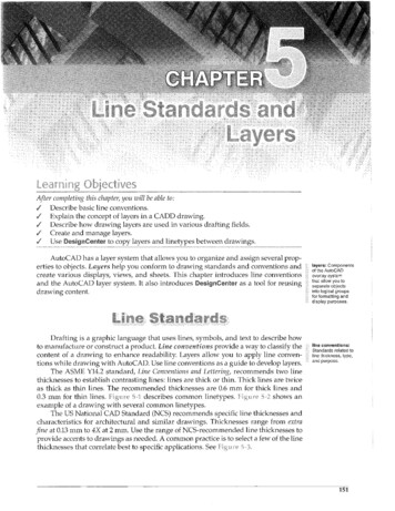
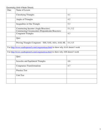
The push for lower energy buildings has resulted in an increase of projects that are looking to usethick layers ( 1.5 inches) of exterior insulation on their buildings. This increase resulted in anincrease in questions regarding the effectiveness of using furring strips attached through theinsulation back to the structure.In reaction to this, research into the performance of these systems has been funded by severalgroups such as the Foam Sheathing Coalition (FSC), the New York State Energy Research andDevelopment Authority (NYSERDA), and the Steel Framing Alliance (SFA). The focus of thispast research by FSC and NYSERDA/SFA was to try to develop prescriptive code tables forattaching cladding to framing over continuous insulation (Bowles 2010). The tables that weredeveloped used an initial deflection limit of 0.015 in. as a basis for design. By limiting the initialdeflection to 0.015 in., the intent was to keep long-term deflection due to potential creep of thesystem within acceptable limits, though these acceptable limits were not defined.Research conducted by BSC was aimed at expanding on this previous research to include severaltypes of insulation as well as to examine both short-term (initial loading) and long-term(sustained loading) performance of the system (Baker 2013).While short-term capacities of the system were measured, the understanding of the systemmechanics that help to develop the capacities were not well identified. The capacity of thesystem was theorized to be developed from several sources, including the bending strength of thefastener, the bearing strength of the furring and framing members, the compressive strength ofthe rigid insulation, as well as the static friction between the layers.Shear and rotationalresistance provided byfastener to woodconnectionsRotational resistanceprovided by tension infastener andcompression of theinsulationVertical movementresistance provided byfriction between layersFigure 1. Theorized forces providing vertical displacement resistanceThe long-term (sustained loading) tests that were completed were intended to examine the longterm creep effects of the system under sustained gravity load in relatively stable environmentalconditions. The results of the initial testing raised some questions as to the impacts of changingenvironmental conditions on the long-term performance of the system. The analysis of the datadid not show much movement in the systems over the course of the test period (July 2011through January 2012); however, the movement that was noted seemed to indicate that thesystem deflections were influenced by even small changes in environmental conditions, and that2
these changes may have greater impacts on the vertical movement of the furring strips than theeffects of sustained gravity dead loads imposed by the cladding.The research presented in this report is intended to help develop a better understanding of thesystem mechanics involved and the potential for environmental exposure to induce movement inthe system. BSC sought to address the following research questions:1. What are the relative roles of the mechanisms and the magnitudes of the force thatinfluence the vertical displacement resistance of the system?2. Can the capacity at a specified deflection be reliably calculated using mechanics basedequations?3. What are the impacts of environmental exposure on the vertical displacement of furringstrips attached directly through insulation back to a wood structure?1.3 Relevance to Building America’s GoalsThe use of exterior insulation on wall assemblies is an effective means to provide additionalthermal resistance to enclosure assemblies. The technique is particularly well suited to retrofitprojects that might otherwise be limited (in terms of space conditioning energy use reductions)due to existing construction dimensional constraints. This fits directly into the Building Americagoals of substantial reductions in energy consumption. While the energy benefits are apparentand easy to understand, the practical implementation has run into barriers that have slowedwidespread adoption.The results of the research is intended to provide specific guidance for cladding attachment overthicker layers of exterior insulation and evaluate the potential of developing mechanics basedequations as a means of evaluation and des
Cladding Attachment Over Thick Exterior Insulating Sheathing P. Baker, P. Eng, and R. Lepage Bu