Transcription
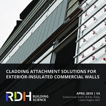
CLADDING ATTACHMENT SOLUTIONS FOREXTERIOR-INSULATED COMMERCIAL WALLSAPRIL 2018 V4Graham Finch, Dipl.T., M.A.Sc., P.Eng. James Higgins, AScT
The material provided in this guide is for information and suggestion only. The greatest care has been taken to confirm the accuracy of the information contained herein; however,the authors, funders, publisher, and other contributors assume no liability for any damage, injury, loss, or expense that may be incurred or suffered as a result of the use of this guide,including products, building techniques, or practices. The views expressed herein do not necessarily represent those of any individual contributor or partner agency.Photography courtesy of:Knight Wall Systems Inc.Cascadia Windows Ltd.Rockwool GroupRDH Building Science Inc. RDH Building Science Inc. 2018rdh.com
CONTENTSIntroduction1Energy Codes and Exterior Insulation2Requirements for Cladding Attachment3Cladding Attachment Systems5Continuous Framing5Vertical Z-Girts6Horizontal Z-Girts7Crossing Z-Girts8Clip and Rail Systems11Aluminum T-Clips12Adjustable Aluminum Clips13Galvanized Steel Clips14Stainless Steel Clips17Thermally Isolated Galvanized Clips18Fiberglass Clips21Long Screws Through Insulation22Masonry Ties24Engineered Anchors and Other Systems25Structural Optimization for Thermal Performance27Thermal Comparison of Systems: A Summary41Other Considerations45Summary47Additional Resources47Learn More47System Overview QuickTable48RDH Building Science Inc.
rdh.com
INTRODUCTIONIn order to meet more stringent energy code requirements, the use of exteriorinsulation installed outboard of wall sheathing is becoming increasingly commonacross North America. Commonly referred to as exterior insulation, this insulationis installed continuously on the outside of the primary structure and—providedExterior-Insulatedthat thermally efficient cladding attachments are used—is more thermally efficientthan insulation placed between studs or inboard of the structural system. As aresult, greater attention is being paid to the design of thermally efficient claddingattachment solutions, and in recent years, several proprietary systems have beenintroduced into the market to meet this demand.Designers and contractors face several challenges in selecting an appropriatecladding attachment strategy for their project. The implications that these decisionshave on effective thermal performance, installation methods, sequencing, andproject costs all need to be considered.Split-Insulated(i.e., exteriorinsulated with studinsulation)The thermal infrared image presented on the following page shows a stuccoclad wall with two cladding attachment systems. On the left of the wall is athermally inefficient continuous vertical Z-girt cladding attachment system, and onthe right is a thermally efficient low-conductivity clip and rail cladding attachmentsystem. The exterior insulation utilizing the continuous girts is less than 25%effective, whereas the exterior insulation utilizing the clip and rail system isapproximately 80% effective—significantly improving the thermal performance ofthe wall for roughly the same construction cost.This bulletin provides guidance regarding different cladding attachment systemsInterior-Insulated(i.e., stud-insulated)for exterior-insulated commercial wall applications.Standard approaches to insulating steel-framedwall assembliesRDH Building Science Inc. 1
ENERGY CODES ANDEXTERIOR INSULATIONVarious energy codes and standards are used across North America. The two mostwidely applicable energy codes are the International Energy Conservation Code(IECC) in the United States, and the National Energy Code for Buildings (NECB) inCanada. The most commonly applied energy standard is ASHRAE Standard 90.1,which is referenced by building and energy codes in the majority of Americanstates and by some Canadian provinces. Different versions and adaptations ofthese codes and standards are in effect across Canada and the US.While different versions and adaptations of these regulations are enforced indifferent jurisdictions, each requires consideration of thermal bridging andeffectiveness of installed insulation. Exterior insulation presents an efficientand cost-effective method to provide improved thermal performance and meetthe requirements of these codes and standards; however, the effectiveness ofthis approach is highly dependent on the use of a thermally efficient claddingattachment strategy. Cladding attachment systems can reduce exterior insulationperformance by as much as 80% for low-performance systems and as little as2–10% for high-performance systems.Thermal infrared image of two different claddingattachment systems: continuous vertical steelz-girts on the left and improved clip and railused on the right2 rdh.com
REQUIREMENTS FORCLADDING ATTACHMENTThere are many factors that must be considered when choosing the typeof exterior insulation and the cladding attachment strategy for a building.These include:ÆÆ Cladding weightÆÆ Wind loadsÆÆ Seismic loadsDiscrete clip andrail type claddingattachment withrigid insulationplaced between clipsupports inboardof the continuousvertical rail. Claddingattached back tovertical rails onexterior of insulation.ÆÆ Fire performance and combustibility requirementsÆÆ Back-up wall construction (wood, concrete, concrete block, or steelframing)ÆÆ Allowable wall thicknessÆÆ Attachment point back into the structure (through studs, sheathing, orslab edge)ÆÆ Thickness of exterior insulationÆÆ Use of rigid, semi-rigid, or spray-applied insulation materialÆÆ Ability to fasten cladding supports directly through the face of rigidinsulation boardsLong screws throughrigid insulationutilizing continuousvertical strappingto create a trusscladding attachmentsystem. Claddingattached to strappingon exterior ofinsulation.ÆÆ Ability to fit semi-rigid or sprayed insulation tightly around discretesupportsÆÆ Effective R-value target and thermal efficiency loss from attachmentsystemÆÆ Orientation and required attachment location for cladding system (panel,vertical, horizontal)ÆÆ Details for attachment of cladding at corners, returns, and penetrationsÆÆ Ease of installation for the claddingÆÆ Accommodation of dimensional toleranceMasonry ties withsemi-rigid insulation.The tie supports hereprovide only lateralresistance support,not gravity load(supported at thebase of the veneer).The design of the cladding attachment system will typically be undertaken by astructural or façade engineer working for the architect or cladding manufacturer.Some cladding attachment systems have been pre-engineered and designed usingload tables developed by the manufacturer. It is important that the claddingattachment designer understands the requirements of the project, including thethermal requirement, so that the system and spacing of supports can be optimizedExamples of various cladding attachmentstrategies through exterior insulationto make the best use of the exterior insulation. See Structural Optimizationfor Thermal Performance on page 27 for more information.RDH Building Science Inc. 3
4 rdh.com
CLADDING ATTACHMENT SYSTEMSThere are numerous cladding attachment systems designed for use with exterior insulation.Many different materials are used to make these systems, including galvanized steel,stainless steel, aluminum, fiberglass, composites, and plastic. While each system is unique,the approaches can generically be classified as: continuous framing, intermittent clip andrail, long fasteners, masonry ties/anchors, or other engineered systems.Attachment systems can accommodate a wide range of claddings for buildings of all heightsand exposures. Typically, the heavier the cladding or more extreme the wind load thetighter the spacing of the supports—thereby impacting the effective thermal performance.Attachment systems should be optimized structurally and thermally for the needs of thespecific project.An overview of several different cladding attachment systems is provided in the sectionsthat follow. For each system, a relative cost ( – ), thermal efficiency (e.g., percenteffectiveness of the exterior insulation), and ease of installation ranking is provided. All ofthe systems readily accomodate exterior insulation except where noted.All of the attachment systems can be installed with wood, steel stud, or concrete/concreteblock back-up walls, with most systems lending themselves better to commercial wallcladding rather than residential cladding.The primary focus of this guide is on the thermal performance attributes of each system.Structural, fire, and constructability considerations are discussed briefly; however, furtherinformation regarding performance and testing data should be obtained from productmanufacturers.CONTINUOUS FRAMINGContinuous girt cladding attachment systems are the predecessors to the recently developedmore thermally efficient clip and rail systems. While continuous framing systems do notperform nearly as well thermally, they are still used in some applications.RDH Building Science Inc. 5
VERTICAL Z-GIRTSRelative CostThermal EfficiencyConstructability20–40%This cladding attachment system consists of continuous galvanized steel framingmembers, typically 18- to 20-gauge Z-girt or C-channel profiles attached verticallyto the back-up wall. Girts are spaced to line up with the stud framing behind (every16” to 24” o.c.). Cladding is attached directly to the outer flange of the Z-girts.Where vertically oriented cladding is used, additional horizontal sub-girts may beapplied to the exterior of the verticals.Vertical Z-girts are not a thermally efficient attachment system and are nottypically recommended due to the excessive amount of thermal bridging. Exteriorinsulation installed between vertical Z-girts is degraded significantly and is only20–40% effective for typical applications. While thermal breaks and/or washers atthe sheathing can be beneficial (approximately 5–10% improvement), the insulationis still largely bridged, making the improvement mostly to surface temperaturerather than the effective R-value. Continuous girts often don’t meet prescriptivecode requirements and are very difficult to use in achieving necessary effectiveR-value performance in a trade-off or modeled approach.Vertical Z-girt over steel stud wall assembly. Girtsare fastened to studs behind at every 16” o.c.resulting in significant thermal bridging throughthe exterior insulation.6 rdh.com
HORIZONTAL Z-GIRTSRelative CostThermal EfficiencyConstructability30–50%This cladding attachment system consists of continuous galvanized steel framingmembers, typically 18- to 20-gauge Z-girt profiles attached horizontally to steelstuds or a concrete back-up wall. Girts are attached to the back-up wall every 24”to 48” o.c. depending on cladding loads. Cladding systems are attached directlyto the outer flange of the girts. Where horizontally oriented cladding is used,additional vertical sub-girts may be applied to the exterior of the horizontals.Similar to continuous vertical z-girts, horizontal Z-girts are not a thermallyefficient attachment system and not typically recommended due to the excessiveamount of thermal bridging. Exterior insulation installed between horizontalZ-girts is degraded significantly and only 30–50% effective for typical applications.The horizontal configuration has slightly improved thermal performance oververtical Z-girts because of the increased spacing between the girts and reducedmetal cutting through the insulation. This system can be improved slightly(approximately 5–10%) with the use of low-conductivity isolation thermal breaks/washers between the framing and back-up wall.Horizontal Z-girts over a steel stud wallassembly. Girts are fastened every 36” o.c. toreduce the thermal bridging as compared totypical vertical arrangements at 16” o.c.RDH Building Science Inc. 7
CROSSING Z-GIRTSRelative CostThermal EfficiencyConstructability40–60%This cladding attachment system consists of two continuous galvanized steelframing members, typically 18- to 20-gauge Z-girt profiles attached in a crossingpattern to steel studs or a concrete back-up wall. Typically, girts are spaced every16” to 24” o.c. or more depending on the back-up framing and cladding loads.Cladding systems are attached directly to the outer flange of the exterior girts.Like vertical or horizontal Z-girts, crossing Z-girts are not a very thermally efficientattachment system and not typically recommended due to the excessive amountof thermal bridging. Exterior insulation installed between crossing Z-girts isdegraded significantly, even though the attachment occurs intermittently, andis only 40–60% effective for typical applications. This system can be improvedslightly (approximately 5–10%) with the use of low conductivity isolation thermalbreaks/washers between framing and back-up wall, or between the crossing girts.8 rdh.com
Crossing Z-girt cladding attachment system withcustom punched vertical Z-girt profiles used toretain exterior insulation.RDH Building Science Inc. 9
10 rdh.com
CLIP AND RAIL SYSTEMSClip and rail systems are a more thermally efficient approach to cladding attachment thancontinuous framing and can support all types of cladding. This includes board and lapcladding installed using standard nail/screw fasteners, stucco/adhered veneers, stoneveneers, and a wide range of metal, glass, and composite cladding systems, each withunique support conditions.Clip and rail systems consist of vertical and/or horizontal girts (rails) attached to or throughintermittent clips that are attached back to the structure through the exterior insulation.Typically, only the clips penetrate the exterior insulation; however, in some designs, theweb of the rail may also cut through part of the insulation. In such cases, the web degradesthe thermal performance of the system—similar to the continuous vertical/horizontal girtsystems—and should be avoided as much as possible. The rails are typically made fromgalvanized steel Z-girt or hat-channel sections, or aluminum extrusions. The clips are madefrom a range of materials including galvanized steel, stainless steel, aluminum, fiberglass,plastic, or some combination of these materials. It is important to note that dissimilarmetals (i.e., aluminum and steel) are typically isolated to prevent galvanic corrosion. Theless conductive the clip material and the fasteners that penetrate the insulation, the morethermally efficient the system will be. This is why stainless steel or fiberglass systems canperform better than galvanized steel or aluminum, and why stainless steel fasteners maybe beneficial compared to galvanized steel fasteners.The overarching strategy with clip systems is to maximize the spacing and use as fewclips as possible while meeting the structural requirements. The maximum clip spacingis typically governed by the cladding wind loads and stiffness of the rail section. Stiffnessconsiderations for support of some cladding systems such as stucco may also dictatespacing requirements. Low conductivity clips are also beneficial since more clips mayinevitably be needed at detail locations. While consideration of additional clips at details isnot necessarily accounted for in current energy codes, it will likely become a requirementin the future as thermal bridging at such locations becomes a central concern.RDH Building Science Inc. 11
ALUMINUM T-CLIPSRelative CostThermal EfficiencyConstructability40–70%This clip and rail attachment system utilizes clips made of a thick, aluminum,T-shaped extrusion with horizontal girts attached on top of the clips. The horizontalgirts cut through a portion of the exterior insulation to allow for adjustability andlonger spans between clips; unfortunately, this reduces the thermal performanceof the system. Where needed, vertical rails are attached to the horizontal girts.As aluminum is more than four times as conductive as galvanized steel, the keyto this system’s performance is to minimize the number of clips and maximizethe structural efficiency of the exterior rails. Currently, there is one manufacturerof this proprietary system that also integrates other thermal break and materialisolation components into the clip.The thermal performance of this system is dependent on the spacing of thehorizontal girts that penetrate the exterior insulation and on the spacing of theintermittent aluminum clips. The thermal efficiency of the system ranges from alow of 40% up to approximately 70%. Where the horizontal girt is entirely outboardof the exterior insulation the performance is greater.Aluminum T-clip with horizontal Z-girt andvertical hat-track for cladding attachment12 rdh.com
ADJUSTABLE ALUMINUM CLIPSRelative CostThermal EfficiencyConstructability40–70%This clip and rail attachment system utilizes adjustable, aluminum, L-shaped clipswith a plastic thermal break and an integrated receiver slot that allows for an L- orT-shaped steel girt to be slid into place and adjusted for dimensional tolerances.For adjustability, the exterior girts cut partially through the exterior insulation,though this reduces the overall thermal performance of the system.As aluminum is more than four times as conductive as galvanized steel, the keyto this system’s performance is to minimize the number of clips and maximizethe structural efficiency of the exterior rails. Currently, there is one manufacturerof this proprietary system that also integrates a plastic thermal break at the clipconnection to the wall. The performance of this system is dependent on thespacing of the intermittent aluminum clips. The thermal efficiency of the systemranges from a low of 40% up to approximately 70%. Where the exterior girt isentirely outboard of the exterior insulation the performance is greater.RDH Building Science Inc. 13
GALVANIZED STEEL CLIPSRelative CostThermal EfficiencyConstructability50–75%This clip and rail attachment system utilizes intermittent generic metal clipsmade of cold-formed galvanized steel. The clips typically take the form of 16- to18-gauge Z-girts, C-channels, or L-angles in 4–8” lengths with depth to suit theinsulation and/or cladding cavity. Dimensional adjustability can come from theuse of back-to-back L-brackets screwed together as they are installed or fromshims behind the clips. The clips are attached to vertical or horizontal rails, whichare most often Z-girts, hat-channels or C-channels. Cladding is attached directly tothese rails with short screws. The rail sections should not penetrate the insulationas it will degrade the effective thermal performance.The thermal efficiency of a clip and rail system with galvanized steel is impactedby the spacing, gauge, and length of the clips. Typically, clips are spaced every 16”horizontally and 24–48” vertically depending on the cladding loads. The thermalefficiency of a galvanized steel clip and rail system can range considerably fromless than 50% to as high as 75%.In addition to the generic options available, there are some manufacturers whonow produce pre-made engineered galvanized steel clips.14 rdh.com
Generic adjustable back-to-back L-anglestainless steel clip and rail systemRDH Building Science Inc. 15
Stainless steel clip and rail system16 rdh.com
STAINLESS STEEL CLIPSRelative CostThermal EfficiencyConstructability65–90%This clip and rail system is very similar to the galvanized steel clip option describedpreviously, but utilizes clips made of stainless steel profiles (rails remain asgalvanized steel). Stainless steel is over four-times less conductive than galvanizedsteel, and therefore more thermally efficient. Due to the lower conductivity of theclips, this system performs quite well with thermal efficiencies in the 65 to 90%range depending on spacing and clip dimensions.In addition to the generic options available, there are a few manufacturers whonow produce and sell stainless steel clips including a pre-punched back-to-backL-bracket allowing for site adjustability. Some manufacturers have introducedaerogel insulation or other low-conductivity thermal break materials to furtherimprove the performance of their stainless steel clips.Intermittent stainless steel clips with vertical girtsRDH Building Science Inc. 17
THERMALLY ISOLATED GALVANIZED CLIPSRelative CostThermal EfficiencyConstructability50–90%This clip and rail attachment system consists of proprietary heavier gaugegalvanized steel clips with 1/8” to 1/2” plastic pads/washers installed betweenthe clip and back-up structure. Plastic washers may also be used at fasteners tofurther reduce the heat transfer. Vertical or horizontal girts are attached to theclips using screws and the cladding is attached to these girts. There are currentlymultiple manufacturers of similar products in the market with varying thermal andstructural performance.In terms of thermal performance, the plastic components can reduce the heatflow through the galvanized steel clip to performance levels similar to stainlesssteel clip systems. Again, the key to maximizing the thermal performance of thissystem is to reduce the number of clips required. The thermal performance ofthis system varies between 50% and 90% depending on the manufacturer’s detailsand spacing. Thermal performance is greater in systems that keep the verticalor horizontal girts entirely outboard of the insulation or minimize the partialembedment of the vertical or horizontal T- and L-angle rails, as shown in the lowerimage at left.Thermally isolated galvanized steel clip attachedto wall with screws through plastic isolated pad18 rdh.com
Thermally isolated galvanized clip and railsystemsRDH Building Science Inc. 19
Fiberglass clips with vertical Z-girts attached withscrew fasteners through the fiberglass clip intothe back-up wallFiberglass clips with horizontal Z-girts attachedwith screw fasteners through the fiberglass clipinto the back-up wall20 rdh.com
FIBERGLASS CLIPSRelative CostThermal EfficiencyConstructability70–95%This clip and rail system utilizes low-conductivity fiberglass clips. Fiberglassis approximately 200 times less conductive than galvanized steel and its usesignificantly improves the thermal performance of attachment systems. In thesystem shown in the adjacent figures, one or two long galvanized or stainlesssteel screws run through each fiberglass clip directly connecting the vertical orhorizontal galvanized steel rail to the structure. Other clips use two separatescrews: one to attach the clip to the structure and the other to attach the rails tothe clips. This latter system utilizes the clip as part of the load transfer path ratherthan simply as a spacer; therefore, the adequacy of the screw connection to thefiberglass is important. Fire performance of these systems should also be verified.Metal Z-girts or hat-channels are used as the vertical or horizontal rail elementsentirely on the exterior of the insulation. Some manufacturers pre-attach the railsto the fiberglass so that they can be screwed to the wall as one element, speedingup installation time.The thermal performance of a fiberglass clip and rail system is heavily dependenton the spacing of the clips and type of screw fasteners used (galvanized versusstainless) and ranges from 70% with tightly spaced clips for heavier claddings toover 90% with optimally spaced clips for lighter claddings.RDH Building Science Inc. 21
LONG SCREWS THROUGH INSULATIONRelative CostThermal EfficiencyConstructability75–95%This cladding attachment system utilizes long fasteners that connect girts orstrapping on the exterior of rigid insulation (including EPS, XPS, Polyiso, andrigid mineral wool) directly into the structure. The combination of the continuousexterior strapping/girts, long fasteners, and rigid insulation create a truss systemconsisting of the screws and struts within the insulation. This truss system is usedto support light- to medium-weight cladding systems. The only thermal bridgesthrough the exterior insulation are the long screws. Claddings are attached directlyto steel girts or wood strapping on the exterior surface of the insulation. Verticalstrapping is used as it provides a vertical cavity for drainage and ventilationbehind the cladding along with greater load-carrying capacity; however, horizontalstrapping can also be used for some claddings.Typically, 18- to 20-gauge galvanized steel hat-channel profiles, a minimum of¾” plywood, or 1x3 or 1x4 dimensional lumber are used for the exterior girts/strapping. It is also typical that the fasteners consist of #10 to #14 steel screwsevery 12–16” o.c. in lengths to connect the exterior girt/strapping to the back-upstructure (studs, sheathing, or concrete). The required screw length can oftenLong screws through metal girts and rigidexterior insulation22 rdh.com
Mock-up of fasteners through plywood strappingand insulation into CLT back-up wallbe estimated to match the thickness of exterior insulation plus 1½”–2” so as topenetrate the sheathing and back-up framing.One challenge installers face with this system is the positive connection of thescrew fasteners back to the structure. With wood framing, this can be achievedby either hitting the studs or designing the plywood or OSB sheathing for therequired pull-out resistance. Typically, in wood frame construction, this can beachieved by upgrading to ¾” plywood or OSB depending on the fastener typeand pull-out loads. With steel studs, this requires careful alignment to hit but notstrip the studs. With concrete and concrete block back-up, this requires specialconcrete or masonry fasteners and, again, care not to strip the fasteners duringinstallation.The thermal performance of this system depends on the back-up wall, type offastener, and fastener spacing. For typical conditions (fasteners every 12” verticallyby 16” horizontally), the insulation effectiveness will be in the range of 75% to 85%for galvanized screws in steel frame or concrete back-up, and as high as 90% to95% for stainless steel screws in wood frame back-up.When using this approach, special attention should be paid to the impact ofthe fastener penetration through the air and watertightness of the sheathingmembrane. Unlike clip and rail or girt systems installed before the insulation,which can be sealed with field-applied sealant, a long screw penetration cannotbe effectively sealed after installation. For this reason, this cladding attachmentsystem is best suited for low-rise wood frame buildings with lower rainwaterexposure. For mid- to high-rise buildings with greater exposure or sloped walls/roofs, the use of a clip and rail system where the clip fasteners can be sealedbefore installing insulation is typically recommended.RDH Building Science Inc. 23
MASONRY TIESRelative CostThermal EfficiencyConstructability40–90%Masonry veneer systems are supported by gravity bearing supports (shelf angles,corbels, etc.) and intermittent ties for lateral and out of plane support. Masonryties bridge the exterior insulation similar to other cladding attachment systemsand are therefore thermal bridges. There is a range of proprietary and genericmasonry tie systems available in the market and the thermal efficiency spans fromfair to excellent at a range of approximately 40–90% depending on the numberof ties and the type and gauge of metal used (stainless steel being the optimalchoice).Masonry ties installed through exterior insulation24 rdh.com
ENGINEERED ANCHORS AND OTHER SYSTEMSIn addition to the various cladding attachment systems presented in this bulletin,there exist many opportunities for engineered approaches and adaptations ofexisting systems.Stone veneer systems have long used heavy-gauge engineered clips to structurallysupport heavy claddings and have adapted configurations to support through afew inches of exterior insulation. Many of these heavier gauge steel anchors will belarge thermal bridges, and thermal modeling is suggested to assess opportunitiesfor improvement, including spacing optimization or incorporation of thermalbreak materials.An example of a heavy-duty engineered cladding anchor support system is shownbelow where large steel plates have been bolted into the concrete structure at 10to 12-foot spacing. A proprietary rail system spans over top of the steel plates tosupport the panel cladding system.Cladding manufacturers are constantly developing new and improved supportsystems. The list of available cladding attachment systems covered within thisbulletin will continue to grow and modification of existing systems will becomemore commonplace. Such examples include the use of discrete fiberglass clips oraluminum and plastic clips to support composite metal panels.Example of heavy-duty engineered anchorconsisting of large welded steel plates and avertical rail systemRDH Building Science Inc. 25
Examples of thermally improved discretecladding attachments for composite metalpanels26 rdh.com
STRUCTURAL OPTIMIZATIONFOR THERMAL PERFORMANCEIt is important to optimize cladding attachment systems so the thermalperformance of the wall assembly can be maximized while maintaining sufficientstructural strength and deflection resistance for the anticipated loads. This sectionprovides an overview of the various structural considerations for optimization ofthe cladding attachment system.The structural design of clip and rail systems requires consideration of at least fiveseparate components used to transfer the structural cladding load to the buildingstructure: The connection between the cladding and the continuous rail/girt system The rail/girt system itself (in some cases multiple layers arranged in a grid) The connection between the rail and the primary clip/girt The primary clip itself (penetrating through the exterior insulation) The connection between the primary clip and the
attachment strategy. Cladding attachment systems can reduce exterior insulation performance by as much as 80% for low-performance systems and as little as 2–10% for high-performance systems. Thermal infrared image of two different cladding attachment systems: continuous vert