Transcription
TIMBER ROOF TRUSSESTIMBER ROOFTRUSSESThis text introduces subject matter related to the manufacture and installation oftimber roof trusses. It builds on knowledge and skills acquired during the first stage,which should be revised and practiced throughout the course.Reference may be made to “Basic Building and Construction Skills”, produced byTAFE and Addison, Wesley, Longman Australia Pty Limited, to re-examine andreinforce these basic skills.The main areas covered are:Truss types and connectors for gable and hip roofs and the erection procedure forboth gable and hip roofs, including gambrel or Dutch-hip ends and flashings.Also covered is the identification of truss types and quantities of each, based on trusslayout plans.Note: Only pre-fabricated trusses and their erection are dealt with. This text does notcover site manufacture or alteration.A comprehensive ‘Glossary of Terms’ is included at the end of the text, whichprovides a detailed description of trade terms, technical content and some tradejargon. TAFE NSW Construction & Transport Division1
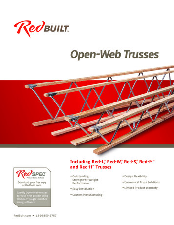
CARPENTRY - HOUSINGINTRODUCTIONROOF TRUSSESA roof truss may be defined as being: ‘an unyielding frame designed to span ortransfer loads between supports.’Trusses have been used for building construction since the early Roman Empire daysto create large open expanses of roof area. The simplest and most commonly usedtype for short spans is the King post truss, shown below:Fig. 1 King post trussLarger spans saw the introduction of the Queen post truss, shown below:Fig. 2 Queen post truss2 TAFE NSW Construction & Transport Division
TIMBER ROOF TRUSSESDECORATIVE TRUSSPublic buildings, such as churches, demanded a more ornate appearance than thesimple King and Queen post trusses. This meant that trusses not only had to providestructural support, but they had to be aesthetically pleasing to the eye. Trusses withornate built-up sections were constructed, such as the highly ornate Hammer beamtruss, shown below:Fig. 3 Hammer beam truss and ornate sectionsOTHER TRUSS TYPES Belgian truss Bell truss Bowstring truss Cambered Finktruss Cantilever truss Crescent truss Double Howe truss Double-W truss Fan truss Fink truss French truss Girder truss Half truss Hammer beamtruss Hip truss Howe truss Inverted cantilevertruss Jack truss King post truss Monopitch truss Parallel chord truss Pitched truss Pratt truss Queen post truss Sailover truss Sawtooth truss Scissored paralleltruss Scissor truss Southlight truss Truncated truss Umbrella truss TAFE NSW Construction & Transport Division3
CARPENTRY - HOUSINGCATEGORISING TRUSSESThese trusses fit into three basic categories, according to the shape of their upperchord:1.2.3.1.Triangular roof trussesCrescent roof trussesRoof trusses other than theseTriangular Roof Trusses:These contain the most common types of trusses used for building. Triangularroof trusses may be identified by the web bracing used and the simple triangulargeometric shape used throughout their design. The top chords are straight.FINK TRUSSKING POST TRUSSPRATT TRUSSHONE TRUSSMODIFIED FINK (long span)SAW TOOTH TRUSSESFig. 13.4 Typical triangular roof trusses2.Crescent roof trussesWhen the top chord of the truss becomes bent or curved the trusses are referredto as crescent trusses. The Sydney Harbour bridge is a large version of aBowstring or crescent type truss.CRESCENT TRUSSESFig. 5 Typical crescent roof trusses4 TAFE NSW Construction & Transport Division
TIMBER ROOF TRUSSES3.Roof trusses other than theseTrusses, which do not come under the title of triangular or crescent types, may beregarded in a class of their own. This class takes in trusses, which have top andbottom chords parallel, or almost parallel to one another, similar to those usedfor bridge buildingOPEN WEB JOISTPARALLEL CHORD TRUSSFig. 13.6 Various trussesFig. 7 A well known trussed structure - Sydney Harbour Bridge TAFE NSW Construction & Transport Division5
CARPENTRY - HOUSINGTerminology:Abbreviations: BC - Bottom chord, HTC - Horizontal top chord, TC - Top chord,TG - Truncated girder (truss), TS - Truncated standard (truss).Camber: This is an upward curvature built into the bottom chord to compensate forlong-term deflection caused by dead loads, such as roof tiles.Gable-end truss: This is the first truss at a gable end. It is also known as a Rakingtruss.Girder Truss: This is a truss that supports other trusses or beams. It may have astandard truss shape or a truncated truss shape, depending on where it is situated in theroof.Nailplates: These are patent-type metal connectors made from a light gauge galvanisedsteel with teeth formed from the plate, by punching them through from one side. Thenailplates are normally pressed from both sides to form a spliced or gussetedconnection.Overhang: This is the section of the truss top chord found within the horizontal eaveswidth area. It runs from the pitching point to the end of the plumb cut at the fasciaposition.Raking Truss: This is a gable-end truss, which has the top chord lowered, by thewidth of the top chord, to allow outriggers to be placed over the top to support thebarge and eaves.Reinforced-head nails: These are nails with either an enlarged shank beneath the nailhead, or have a specially tapered head with enough thickness to eliminate thepossibility of the head becoming brittle during driving or under load, and breaking off.Station: This is the position of a truncated truss, a truncated girder truss, or a gambrelgirder truss, as measured from the pitching point t the near face of the truss.Structural fascia: This is fascia of the type capable of distributing overhang loads toadjacent trusses. Solid timber fascia would be a typical example of this.Truss engineer: This is a professional engineer, as specified in the BCA, experiencedin the design of nailplated timber truss systems.Valley saddle trusses: These are trusses that are supported on top of other trusses andused to form the roof shape between roof segments.Waling plate: This is a timber member normally fixed to the face of a truss to supportintersecting rafters or trussers, as typically found on the front of a gambrel truss.6 TAFE NSW Construction & Transport Division
TIMBER ROOF TRUSSESROOF TRUSS MEMBERS AND STRESSERS TAFE NSW Construction & Transport Division7
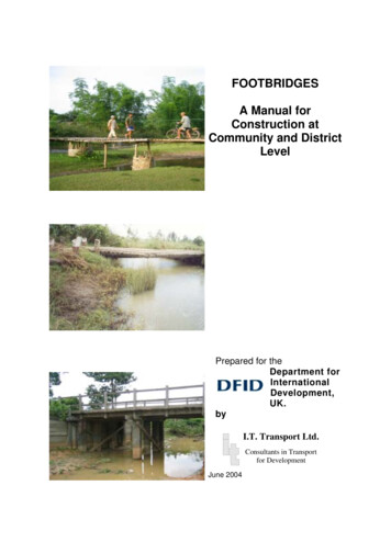
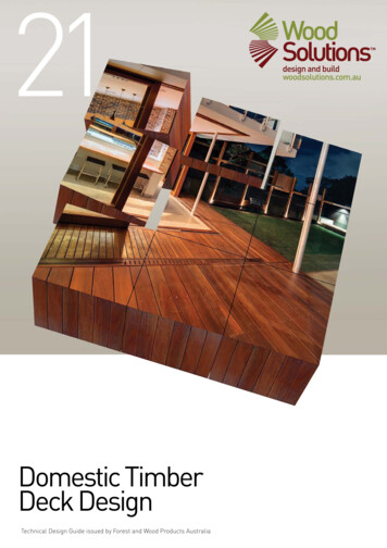
CARPENTRY - HOUSINGSPECIAL TRUSSESParallel Chord TrussesThese trusses are commonly used where large raking or level spans are to be bridgedwith no intermediate support. They provide strength and versatility using relativelysmall individual member section sizes. Parallel chord trusses are ideal for raking roofsand suspended floors as they allow services, like electrical, plumbing, air-conditioning,etc., to be built-in and concealed without having to modify the truss members.OPTIONAL METHODSCONVENTIONAL METHODS‘A’‘B’Rafters on load bearing wallsand beamParallel chord roof truss‘D’‘C’Bearers and joists with piers‘E’Clear span parallel chord floor truss‘F’IUniversal beam, deep floor joistsCantilevered with post supportsCantilevered, parallel chord floor trussFig. 11 Using parallel chord trusses8 TAFE NSW Construction & Transport Division
TIMBER ROOF TRUSSESParallel chord trusses may be used in a ground sub-floor or upper floor situation,provided suitable Class 1 or 2 timbers, or treated timbers, are used where the trussesare exposed to moist conditions.NonLoad bearingLoad bearingPlatform floor const’nPreservative treatedstructural grade ply .Treated base platesAnchor boltsFig. 12 Ground floor systemCantilevers may also be built into the main length of the truss for balconies, howeverunless the timber is treated it may not be used in an externally exposed position.Block-outs may also be built into the design to cater for large sectioned services.CantileverClear spanPlatform floorDuctBottom chordbearingAlternative - Top chord bearingFig. 13 Upper floor system with cantilever TAFE NSW Construction & Transport Division9
CARPENTRY - HOUSINGLAMINATED TIMBER TRUSSApproved plywoodsheathing to both sidesof frameworkLAMINATED PLYWOOD TRUSSLaminated timber trusses have greatindividual member strength, which reducesthe number of members required toconstruct the trusses. They may beconstructed from non-visual gradestructural timbers and covered, or beconstructed of visual grade structuraltimbers and covered, or be constructed ofvisual grade structural timbers and beexposed with a stained or clear finish.Laminated beams and portal frames arealso available, such as the popular’Glulam’ beam system.Vertically laminated plywood trusses arealso available, although not widely used.LAMINATED TIMBER ROOF TRUSSLAMINATED TIMBER SKYLIGHT TRUSSHead shackleTurnbuckleStraining rodTie rodHeel strapTIE ROD TRUSSED RAFTERS (LAMINATED TIMBER)KING ROD TRUSS (LAMINATED TIMBER)Fig. 14 Laminated truss types10 TAFE NSW Construction & Transport Division
TIMBER ROOF TRUSSESTRUSS MANUFACTUREAssemblyThe member sizes, stresses and truss designare prepared by a professional truss engineerand must not be designed or manufactured byany other person, unless under the directsupervision of the engineer.The trusses are manufactured in a controlledfactory environment with members beingcalculated, cut and assembled usingcomputerised machinery.The members are set in position using a jigand joints are connected with patent typenailplates, on both sides of the connection,which, which are pressed into the timberusing a static or mobile press.HeelplateGANGNAIL OR NAILPLATE TYPESNailing pattern must beEngineer designedNAILED PLYWOOD OR TIMBER CLEATBOLTED STEEL FISHPLATEFig. 15 Methods of connecting membersat panel pointsNailplatesThe nail sections are punched out of a solidplate body to protrude from one side,allowing the plate to sit flat when pressedor hammered.Claw-type plates are usually pressed,whereas Knuckle-type plates may be drivenwith a hammer.Fig. 16 Nailplate types TAFE NSW Construction & Transport Division11
CARPENTRY - HOUSINGDriving NailplatesNailplates may be driven using ahammer, but this method would onlybe used where a press is unavailablesuch as an on-site truss repair ormodification.Note: Manually driven nailplates arenot suited for general roof trussmanufacture.Hammered or hydraulically pressedFig. 17 Hammer driven connectorCamberTrusses are fabricated with a slightcamber in the bottom chord.The camber is designed to provide acalculated maximum deflection, basedon the span and load of the roof.Built-in camber fordeflectionThe camber is progressively taken upwhen deflection occurs due to roof loadsbeing applied, such as roof tiles, ceilinglinings, etc.Under no circumstances should trussesbe supported along their span, unlessdesigned for, as applied loads may causethe truss to fail.Load12mm minimumclearanceInternal wallFig. 18 Camber and settlement under load12 TAFE NSW Construction & Transport Division
TIMBER ROOF TRUSSESSUPPORT PREPARATION FOR TRUSSESThe structure supporting the trusses must be level and square. Wall plates and beamsmust be load-bearing where the ends of trusses, or intermediate panel points forcantilevered trusses, are directly supported.The minimum bearing width for trusses shall be not less than 70mm. If this cannot beprovided the truss engineer should beconsulted.Load-bearing WallsIf standard thickness top wall plates areused, I.e. up to 45mm seasoned, 50mmunseasoned, then trusses must be placeddirectly over wall stud positions.This allows direct transfer of loads from theroof through the walls to the footings,without causing deflection in the plates.If the trusses are not located directly overstuds, or within 1.5 times the thickness ofthe wall plate from the stud, it is consideredto be random loading, which will requiresome reinforcement of the platesThis may be carried out by using a thickertop plate, i.e. 70mm minimum, or doublingthe top plates, i.e. 2/35mm plates, or byfixing additional blocking between studstight under the top plate.Trusses with additional loads applied, suchas a Girder truss, are best supported using astud or studs directly under the ends. Thiswill prevent possible cornice crushing in thefuture. TAFE NSW Construction & Transport Division13
CARPENTRY - HOUSINGInadequate SupportWhen trusses do not align with studs, or platesare not thickened, doubled or blocked, the resultwill be deflection of the top plates, whichinevitably causes cornice crushing and/orceiling lining cracks.LintelsDue to the roof loads being transferred to theexternal walls, it will be necessary to provideadequate support across openings.A suitable timber, steel, or a combination ofboth, lintel will be required having a sectionsize and stress grade as per AS 1684.2-1999Part 2.A common lightweight method of providingsupport is to use standard timber framing and apatent steel type ‘Z’ or’ ’C’ section cold formedlintel.14 TAFE NSW Construction & Transport Division
TIMBER ROOF TRUSSESLintel DetailsSteel patent type lintels areavailable in a variety of sizes for‘Z’ and ‘C’ sections. The sizesare to comply with requirementsof AS 1684.2-1999 Part 2 forlintel loads and spans.The following details provide aguide for design proportions.Fig. 24 Section detailsTable 1Steel Lintel ProportionsDimensionsTypeadctTF 135147451.6TF 235147452.0TF 340219452.5TF 445264453.0Laminated Timber LintelsType A : Laminated veneerlumber (LVL) lintels andbressumers are verticallylaminated veneers of timber,which give the appearance ofbeing a very thick plywoodmember.Type B: Glue laminated timberlintels and beams are constructedof engineered hardwood orsoftwood timbers horizontallylaminated to form a strongermember than solid timber.They may be plastic wrapped orwax coated for surface protectionfrom exposure duringconstruction. TAFE NSW Construction & Transport Division15
CARPENTRY - HOUSINGLIFTING and STORAGE of TRUSSESLifting TrussesWhen lifting, care must be taken to avoid damaging the timber and the joints or panelpoints.Never lift a truss by its apex joint only as this may cause the truss joints to separate.Always use a spreader bar to lift trusses to spread the load evenly and remove thepressure from joints.The following details show how different types of up to 9.0m, types 2a to 2e areconsidered to have large spans of 9.0m to 18.0m.16 TAFE NSW Construction & Transport Division
TIMBER ROOF TRUSSESBundle LiftingA number of trusses may be lifted into place at the one time, provided they areproperly tied or banded together and lifted form the designated slinging points. Thismethod of lifting same size trusses speeds up the lifting and placing process.SlingBandingEnd WallBandingLay flatFig. 27 Bundle lifting methodStorage of TrussesTrusses should be inspected when they arrive on-site and any damage reported. Theyshould not be site repaired without consultation with a truss engineer.When stored on-site they should be placed on timber gluts, or dunnage, to keep themclear of the ground to allow flat storage and to avoid member distortion.5Rotate truss upwards, fix and brace intoa vertical positionSide truss into position4Place top chord against plate andslide truss up carefully3Carry truss with apexpointing downTruss bundle laid flat and levelFig. 28 Lifting trusses by hand TAFE NSW Construction & Transport Division17
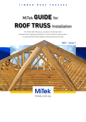
CARPENTRY - HOUSINGERECTING AND FIXING TRUSSESGable RoofThe gable roof is the simplest style of roof to construct using trusses. All the trussesare exactly the same shape and size, except where raking trusses are used, making it avery quick and efficient system to use.Note: Installation of timber trusses comply with AS4440-1997 Installation ofnailplated timber trusses.MethodStep 1Truss positions may be marked out prior to erection, although with a straightforward gable roof this is not necessary.The trusses are lifted onto the wall frames and stacked in positions where theyare easily retrieved for erection. The stacks of trusses should be spaced farenough apart to allow progressive erection without having to move a stack out ofthe way . For example, if each stack has 5 or 6 trusses the first stack should beplaced at least 5 or 6 spacings away from the position of the first truss to beerected from that stack.This prevents the need for double handling and unnecessary moving of trusses.Step 2Start with a gable or raking truss at each end by aligning the heels of the trusseswith the outside of the wall plates.Erect and attach temporary braces to each end truss, holding them plumb, as allsubsequent trusses are spaced from and attached to them.Note: External bracing is preferred to prevent the temporary braces forminterfering with the next truss position.A string line is attached to the apex of the gable trusses and pulled taught toallow all subsequent truss apex points to be in-line, within 2mm.Intermediate trusses spaced as required and securedwith temporary bracing battens as erection proceeds.Heels fixed at set-out marks along top plates.Support truss bundleacross several internalwalls where possibleString linePlumb truss andbrace to bottom ofinternal wall. Framemust be fixed to floorGable orrakingtrussBrace externally topeg well anchored inground. Alternatively,brace to internalframework.Fig. 29 Initial truss loading and preparation18 TAFE NSW Construction & Transport Division
TIMBER ROOF TRUSSESStep 3The spacing of trusses is best controlled by using a gauging rod. This issimply a length of batten at least 700mm long, for 600mm spacking, withtwo nails protruding at each end. The nails are set the thickness of thetruss top chord apart and spaced equal to the truss centres.One end of the gauging rodis placed over a fixed truss,with the next truss movedNailsto allow the nails at theother end to hold it in thecorrect position while it isfixed off.Truss centresFig. 13.30 Gauging rod for spacing trussesStep 4The remaining trusses are positioned using the gauging rod, skew nailedat the heel positions and held in place temporarily at the top using battenties, which are tacked to the top chord.String lineGauging rodGable trussGabletrussTie13456Plate7892BraceBraceFig. 13.31 Gable roof trusses set in positionStep 5The ends, or heel positions, of each trussmust be fixed securely to the top wallplates using one patent metal connector,similar to the Trip-L-grip.These connectors provide 3-way fixingbetween the truss chord and wall plateusing supplied flat-head nails.There should be a minimum of 4 nailsinto the chord, 4 nails into the edge ofthe wall plate and 2 nails into the top ofthe plate.38734263Fig. 13.32 Trip-L-Grip metal connectors TAFE NSW Construction & Transport Division19
CARPENTRY - HOUSINGThe following details outline the methodsused to fix trusses to wall plates and providealternative types of connectors for the samepurpose.Available to suit 38mmand 50mm thick timberEach ‘Trip -L-Grip’ must befixed with ten approved nailsfor maximum benefitTRUSS SADDLE4 nails min2 NailsminFig. 34 Multi-grip anchor bracket4 nails min1.2 mm Galv. Steel120mm high38mm wideROOF TRUSS TO PLATEHeel joints of trusses shall be fixed to top plateswith one type AL or AR Trip-L-Grip. Use twoTrip-L-Grips at each heel point in cyclonic areasor where sheet steel, aluminium,or fibrous cement is used.Fig. 33 Conventional Trip-L-Grip connectorStep 6Fig. 35 Multi-grip all-purpose anchorbracketThe gable end, or Raking Trusses, have their top chords set one chordwidth lower than the other trusses. This allows the outriggers, or vergetrimmers, to run over the top of the raking truss to frame up the verge,which holds the barge and eaves lining.Common height of standard trussesVerge trimmersNogging between trimmers20 to 40 x 85Nailplates, typical.300 min20 to 50 x 115Fig. 36 Gable or Raking truss20 TAFE NSW Construction & Transport Division
TIMBER ROOF TRUSSESVERGE FRAMINGGable roof ends may have boxedor raking eaves.The gable truss may be a rakingtruss, or it may also be a standardtruss with short blocking for flusheaves. Specially designed ‘Z’ sprockets, referred to as Gunstocksbecause of their shape, may also beused as an alternative.’ TAFE NSW Construction & Transport Division21
CARPENTRY - HOUSINGStep 7The bottom chords of the trusses need to be attached to internal wallswithout resting on them, unless they are cantilever trusses or they areotherwise designed to be supported internally.Generally, trusses transfer the roof loads to external load-bearing wallsonly, leaving the internal non load-bearing walls free to be placed in anyposition.Depending on the span of the trusses, there should be a minimum gap of10mm between the bottom chord and the top wall plate of internal walls.As there are no load bearinginternal walls, extra piers orstrengthening of concreteslab is not required underinternal partitionsFig. 13.42 Load transfer of roof trussesInternal ‘L’ shaped wall brackets are used to connect trusses to internal walls, whichprevents lateral movement of the trusses and the top of the wall. The wall brackets arefixed between the ceiling trimmers, and the top wall plates with a minimum of 3/30 x2.8mm galvanised reinforced head nails to each bracket leg.Note: The nails in the upright section of the bracket are fixed a the top of the slots toallow for bottom chord deflection movement.Fig. 13.43 Wall bracket details22 TAFE NSW Construction & Transport Division
TIMBER ROOF TRUSSESFixing to Non-bracing WallsIf internal or non-load bearing walls are notdesigned as bracing walls, the trusses are fixedto them using wall brackets.The brackets are fixed at Max. 1800mm centres3 nailsalong support sections of the wall. Wheretrusses are parallel to the walls, ceilingtrimmers are fixed between the truss bottomchords. Where non-load bearing walls arestable in their own right, no internal wallTRUSS AT RIGHT ANGLE TO WALLbrackets are required.Internal Wall Bracketnailed at top of slot.Leave gap betweennail head andbracket to allow forvertical movement oftruss on loadingNote: Ceiling trimmers are to be fixed atmaximum spacings equal to the maximumspacing of trusses. The connection should alsoallow the truss to deflect vertically whenloaded, ie, at least 10mm clearance betweentrimmer and top plate.Fig. 44 Top plate fixing to non-bracing wallsFixing to Bracing WallsWhere internal walls are non-loadbearing but are designed as bracingwalls, the trusses should be fixed to thetop plates using structural connections ofequivalent strength to the bracingstrength of that particular wall.Blocks to be both sides of bottomchordBlockingpieces largeenough toavoid splittingInternal Wall BracketGap to trussThis may be achieved by fixing blockingpieces to either side of the truss orceiling trimmers.Bracing wallRAFTERS OR TRUSSES PARALLEL TO BRACINGNote: The connection should also allowWALLthe truss to deflect vertically when loaded,Shear blocksie at least 10mm clearance betweennailed or boltedtrimmer and top plate.Nailing plates or framing anchor (legs orbent) to either end ofnogging with 6/2.8mmdiameter nails to each faceGap totrussBracingwallBlocking pieceslarge enough toavoid splittingFig. 45 Top plate fixing to bracing walls TAFE NSW Construction & Transport Division23
CARPENTRY - HOUSINGStep 8Fit permanent bracing over the top chords of the trusses onto therigid walls to prevent the roof frame from racking, rotating orbuckling under the load of the roof tiles, ceiling materials or fromwind forces.The most common type of roof bracing is perforated metalSpeedbrace. This is a patent type of bracing system for trussed roofsfor use in both low wind speed and cyclone areas.Speedbrace is a tension bracing system that uses a pre-punchedshallow ‘V’ shaped member that is easily handled and erected. It isapplied in an ‘X’ or ‘V’ pattern to the top chords, which braces thetrusses back to the frame.20 20SPEEDBRACERidgeRoof battens must becontinuous in this area120 Roof battens must becontinuous in this areaBracing at 30 to 45 to wall topplate when viewed on planFig. 46 The Speedbrace systemFixing MethodsEnds should be wrapped around members as required and fixed off using 2/30 x 2.8mmgalvanised reinforced head nails at each fixing position. Do Not use clouts.Note: See manufacturer’s details for bracing designs of short to long roofs.45 or lessRoofbrace secured to side of top-plate withtwo clouts and then bent around and fixed tobottom of plate with three nailsFig. 47 Heel end fixing24Use bracketseach side oftruss heelSpreader blockfixed to plate with three nailsand double nailed each endthrough truss chordsFig. 48 Alternative heel end fixing TAFE NSW Construction & Transport Division
TIMBER ROOF TRUSSES3 nails tooverlappedspliceEnd of bracebent down overtop chord of endtruss and fastened to the facewith three nails2 Nails to eachchord2 nailsSpliceRoofbraceRoofbraceEnd trussTruss top chordFig. 49 Splice detailStep 9Fig. 50 Fixing to apex of end trussPermanent bottom chord braces, or Longitudinal braces, are required tohold the truss bottom chords straight under load.For battened ceilings use batten sizes as specified by AS 1684.2 Part 2.Battern centres are not to exceed restrain centres specified on trussdesign drawings.Bottom chord ties, and diagonal bracing may be required for suspendedceilings or where ceiling battens do not provide restraint to bottomchords, e.g. metal furring channels clipped to trusses.Fit bottom chord ties for trusses at close centres with ceilings fixeddirectly to bottom chords with glue or nails. Bottom chord ties shouldbe fixed and/or braced back to a rigid building element, such as an endor party wall.The braces are normally fitted as close to the bottom panel points aspossible to maintain lateral rigidity.Longitudinal ties (bottom chord bracing)Fig. 13.51 Bottom chord or longitudinal bracing TAFE NSW Construction & Transport Division25
CARPENTRY - HOUSINGSPECIAL NOTES ON TRUSS ERECTIONTemporary bracingAll trusses must be temporarilybraced during the erection processto avoid the following: Collapse during erection; or Erection tolerance will beexceeded, causing overloading,buckling and possiblepermanent damage.The first truss should be erectedstraight and plumb, within erectiontolerances, and temporarily bracedto a rigid element, such as a wallor to a peg in the ground.Each successive truss should bespaced using a gauging rod, asshown previously on page 19, thenfixed back to the first truss withtemporary ties at each top chordpanel point. Use minimum 50 x 25battens for trusses paced up to 900centres.Temporary post fixed to wallframe. One per top chordpanel pointTrussesGableTemporary longitudinal tiesto the top of truss top chordsat panel pointsWallTrussesWallFig. 52 Methods of temporary bracing first trussNotes: The purpose of temporary bracing is to hold trusses straight and plumb prior tofixing permanent bracing. All permanent bracing, ties, hold down ties, etc. must becompletely fixed off prior to loading the roof.Erection TolerancesPlumbWorking to acceptable tolerances iscritical to maintain a good roof line andHeighteffective bracing. A stringline, plumbbob and/or level and straight-edge shouldbe used. The following tolerances areLesser of 50mmBowheight/50considered acceptable to AS 4440-1997Installation of nailplated timber trusses:Lesser of 50mm or L/2001. Trusses to be erected with overallbow, or bow in any chord, not toexceed the lesser of L/200 or 50mmLesser of 50mm or L/200(when L is the length of the chord);2. Erect trusses with the apex at notFig. 53 Tolerances for bow and plumbmore than the lesser of span/200mmor 50mm from a vertical planethrough the supports; and3. At any section, the local out-of-plumb should not exceed the truss height/50 or amaximum of 50mm.Note: Generally, if a bow or tilt is evident to the eye, the truss is outside thetolerances.26 TAFE NSW Construction & Transport Division
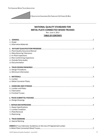
TIMBER ROOF TRUSSESALTERNATIVE ROOF STYLESThere are many other commonly constructed truss roof styles, apart from the gable,which follow similar erection procedures and have similar shaped trusses. However,due to the change in at least part of the roof shape, new truss types are introduced. Thenew truss types are used to form the following common shapes:Truncated GirderHip Truss/RafterDutch Hip GirderJackTruss/RafterRidge LineJackTruss/RafterRidge LineStandard TrussStandard TrussFig. 54 Hip roofTruncatedGirderHip Truss/RafterStandard trussRidge LineFig. 55 Dutch hip or Gambrel roofHip Truss/RafterRaking d TrussRidge Verge TrimmingRakingTrussVerge TrimmingFig. 57 ’T’-shaped hip and valley roofFig. 56 ’L’-shaped hip and valley roofBell Truncated GirderRidge LinesHip Truss/RafterJack Truss/RafterStandard TrussFig. 58 Bell or Bellcast roof TAFE NSW Construction & Transport Division27
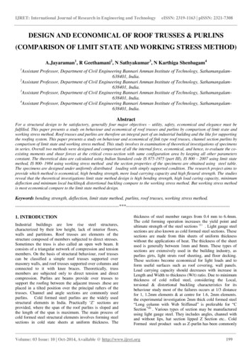
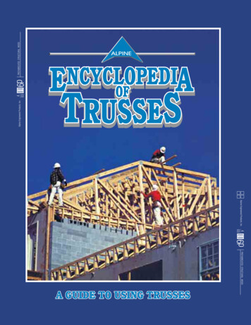
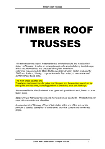
CARPENTRY - HOUSINGHIP ROOF TRUSS TYPESApart from the basic triangular shape of the Standard roof truss, there are severalspecial purpose trusses used to form hip roofs, and variations of the hip roof.These truss types are shaped to form the finished roof surface and are placed instrategic positions. Hip and jack truss types may also be made up of single sticktimber members for smaller roofs of where the distance to station positions is notexcessive.JACK TRUSSTruncatedgirder trussEnd wallTruncatedstandardtruss* NOTE: Extended top chord intersectswith extended top chord of Hip TrussHIP TRUSSWall cornerTRUNCATED STANDARD TRUSSTruncatedgirder trussTruncatedstandard trussNOTE: Top chord extends to intersection atapex of Standard A - Type TrussSide wallSide wallA. STANDARD ‘A’ - TYPE TRUSSB. TRUNCATED STANDARD TRUSSC. TRUNCATED GIRDER TRUSSKEY PLAN TRUSS LOCATIONSD. HIP TRUSSE. JACK TRUSSFig. 59 Various truss types28 TAFE NSW Construction & Transport Division
TIMBER ROOF TRUSSESTRUSS TYPE LOCATIONSTANDARD GIRDER TRUSSSaddle trussesRaking trussStandard GirderStandard trussesStandard truncatedTruncated GirderHip
Trusses, which do not come under the title of triangular or crescent types, may be regarded in a class of their own. This class takes in trusses, which have top and . Nailplates: These are patent-type metal connectors made from a light gauge galvanised steel with teeth formed from the plate, by punching them through from one side. The