Transcription
T I M B E RR O O FT R U S S E SMiTek GUIDE forROOF TRUSS InstallationThe Timber Roof Trusses you are about to install have beenmanufactured to engineering standards. To ensure that the trusses perform,it is essential that they be handled, erected and braced correctly.2021 - Issue 1
TABLE OF CONTENTSFixing & Bracing Guidelines For Timber Roof TrussesGeneral. 3Design. 3Transport. 3Job Storage. 3Roof Layout. 4Erection and Fixing. 4Girder and Dutch Hip Girder Trusses. 7Saddle Truss Fixing. 11Roofing Battens. 12Permanent Bracing. 12Web Ties and Stiffeners. 17Girder Brackets. 21Guard Rail Systems. 27MiTek 20/20 User Guide. 29Truss Installation Checklist. 36Product Certification. 36ILLUSTRATIONSAll technical illustrations in this Guide have been converted to pdf, AutoCAD 2000 dwg & dxf file formats.They are also compatible for use with MiTek SAPPHIRE - making them the ideal, easy reference for installationinstructions and data. To access these illustrations, please visit our website.This manual is available in the EASYCAT APP. It can be downloadedfrom the Mac App Store or the Google Play Store.mitek.com.au
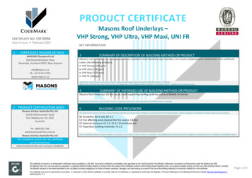
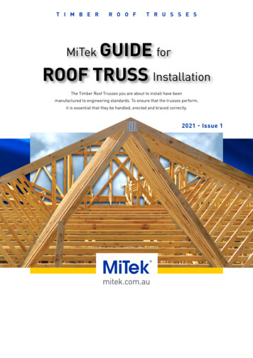
GENERALJOB STORAGE AND LIFTINGThe roof trusses you are about to install have been manufactured toengineering standards. To ensure that the trusses perform as designedit is essential that they be handled, erected and braced correctly.The installation of prefabricated timber trusses is covered by the AustralianStandard AS 4440 “Installation of NailPlated Timber Trusses”. The followinginformation is an abbreviated set of instructions designed to assistwith on site work and is not intended to replace the need to referenceAS 4440. The following recommendations apply to roof trusses on standarddomestic buildings where truss design details are obtained from MiTekengineering programs. Details for commercial, industrial and non standarddomestic buildings, are to be provided by an Engineer responsible for theoverall building design.Trusses should be inspected on arrival at site. Any damaged trussesshould be reported immediately and not site repaired without approval ofthe truss fabricator.Where it is anticipated that trusses will be stored on site for an extendedperiod of time before use, adequate provision should be made to protecttrusses against the effects of weather.Once trusses are installed they should not be left exposed to weather for longperiods. Repeated wetting and drying has a detrimental effect on the strengthof both timber and connection.Protective covering, where used, should allow free air circulation around trusses.Trusses when stored on the job site should be on timber fillets clear off theground and in a flat position to avoid distortion.When lifting, care must be taken to avoid damaging of joints and timber.Spreader bars with attachment to the panel points should be used wherespan exceeds 9000 mm. Never lift by the apex joint only.The trusses may also be placed on the top plates by pulling them up on skids,spread at 3000 mm, taking the same precaution as described above.Ensure that the trusses are not distorted or allowed to sag between supports.The recommended method of lifting trusses will depend on a number of factors,including truss length and shape.In general, sling truss from top chord panel points as shown below.Slings should be located at equal distance from truss centreline and beapproximately 1/3 to 1/2 truss length apart.The angle between sling legs should be 60 or less and where truss spansare greater than 9000 mm a spreader bar or StrongBack should be used.Some typical examples are shown below.DESIGN1. Trusses are designed for normal roof, ceiling and wind loads to suit specificjobs and conditions. Additional loading such as Solar Units, Hot WaterTanks, Air Conditioning, etc. require special consideration. Advice shouldbe sought from the truss fabricator prior to commencing construction.2. Wall frames and beams supporting trusses must be designed for the correctroof loads. Refer AS 1684 “Residential Timber-Framed Construction”for details.3. Wind load is an important factor in the design and performance of rooftrusses. Ensure that you have correctly advised the truss fabricator withregard to wind load requirements and that adequate provision has beenmade to fix trusses to the support structure to withstand wind uplift forces.4. Trusses are generally designed to be supported on the outer wall with innerwalls being non load bearing. Where it is necessary to use internal wallsfor load bearing, these will be clearly shown on layouts. Note that thesupporting structure is stable in its own right.5. Before ordering trusses, ensure that your particular requirements havebeen provided for and that all relevant information has been supplied tothe truss manufacturer. If non standard trusses are being used, ensurethat erection and bracing details are known before erection commences.60 or lessRT001-a6. For environments where the atmosphere may be conducive to corrosion,such as some types of industrial and agricultural buildings, or buildingsnear the ocean and subject to salt spray, consideration should be given tothe use of G8S stainless steel connector plates.Approx 1/2 to 1/3of truss lengthImportant Note1. It is the Builder’s responsibility to ensure that all relevant informationrequired for design is provided to the fabricator at time of orderingtrusses, including spans, pitches, profiles, quantities and loadings.Final confirmation of details by the fabricator with the builder isrecommended prior to manufacture.RT001-b2. Trusses are designed to be part of a structural system, which includesbattens/purlins, bracing, binders, fascias and the connection of thesecomponents. The full strength of trusses is not achieved until allcomponents are installed correctly. All trusses must braced (temporaryand permanently) and stabilised throughout installation of the roof trusssystem. No truss should be loaded until all permanent bracing is fixedand battens/purlins are installed. Installers should not stand on any trussuntil all temporary bracing is fixed in place and the truss is stabilised inaccordance with the following instructions.RT001-c3. A risk assessment shall be undertaken for each site taking into accountall relevant workplace safety practices, including working height. It is thebuilders responsibility to consider the site conditions when determiningprocedures for handling, lifting, fixing and bracing of roof components.The procedures shall be discussed with all employees and sub contractorsworking on site and the agreed methods documented. A useful templatefor this purpose is the “Safe Working Method Statement No. 10” whichis published by the Housing Industry Association (HIA) and available ontheir website. “The National Code of Practice for the Prevention of Falls inHousing Construction” produced by Safe Work Australia contains specificinformation and guidance on risk management for working at heightin the residential construction sector. All safety gear appropriate to thesite and work being carried out shall be worn, including eye protection,foot protection and gloves when handling sharp edges.Spreader barRT001-dApprox 1/2 to 1/3of truss lengthSpreader barRT001-e4. Ensure all bracing is permanently fixed and all brackets are fully installedprior to working on or loading the roof.Strongback tied to eachintersecting webof chord5. Trusses are designed for specific loading, geometry and support conditions.Under no circumstances should any component of the truss be drilled, cut,removed or modified in any way without prior approval from the trussfabricator.RT001-f6. Trusses should not be used or stored where they are subjected to repeatedwetting and drying as this has a detrimental effect on the strength of bothtimber and connections.Approx 1/2 to 1/3of truss length7. If trusses have been designed for timber fascias, do not replace with steelfascia without asking your truss supplier to check the overhang design.Strongback tied totop chord at approx.300mm intervalsTRANSPORTTrusses must be fully supported when being transported in either a horizontalor vertical plane. Care must be taken when tying down, not to put strain onchords or webs.RT001-gTimber or metal right angle protectors are a satisfactory method of avoidingdamage. Unloading and handling is described opposite.Approx 1/2 to 1/3of truss length3RETURN TO INDEX
ROOF LAYOUTNOTE: For 900mm spaced trusses, plasterers prefer to use 50mm battens.A layout for trusses must be determined before erection. If in doubt consultyour truss fabricator.Points circled on these layouts may be critical. Refer to the Wall FrameConstruction notes.Hip EndHip truss/rafterTruncated girderRT002RT007Wall Frame ConstructionRidgeThe load bearing frames should be checked for:Fix at crossing with minimumof1 TRIP-L-GRIP (typical)Dutch HipStandard trussDutch hip girder1. Lintel sizes suitable for truss loading. Consult AS 1684 or your trussfabricator.Jack truss/rafter2. If trusses are not located directly over studs the top plate size must be inaccordance with AS 1684.Hip truss/rafter3. Girder trusses may require the strengthening of studs at the points ofsupport. Check the loading with your truss fabricator and refer to AS 1684.Points circled on the layout notes are critical.The supporting structure construction must be adequate to resist windup-lift forces.RidgeRT003TrussesStandard trussGableJack truss/rafterTop plateRaking trussRT008-aStudsRT004TrussesRidgeRT008-bTop plateVerge trimmingStandard trussLintel at openingNOTE: End gable truss to be located over end wall unless otherwise advisedby supplier.T ShapedRaking trussTop plate strengthening may be required where trusses do not coincidewith studs.Place 75 x 25mm intermediate ties on topStandard chord between saddle trusses where spacingtrussexceeds top chord design restraint centres.TrussesRT008-cTop plateRidgeRT005StudsFrame BracingRidgeVerge trimmingSaddle trussL ShapedGirder trussThe frame must be fully braced, plumb, and nailed home before the erectionof trusses is commenced.Raking trussERECTION AND FIXINGIt is convenient to mark the truss position on the wall plates before liftingtrusses. Use the layout drawing as your guide and note that the truss designspacing must not be exceeded.Verge trimmingTruncated girder Standard trussHip truss/rafterEnsure first truss is installed carefully and within erection tolerances.WARNING – Do not use web as ladder to climb up or down the roof duringinstallation. This can cause damage to the web and lead to serious injury.Jack truss/rafterGirder trussRidgeGABLE ROOFS – start with a gable truss at each end, fixing it to the top plateat the position marked. These trusses must be temporarily braced back to theground or frame at the panel points.Saddle trussRT006Girder trussRidgeIntermediateties as aboveHIP OR DUTCH GABLE – start with the Dutch girder truss or the truncatedgirder, placing it on the top plate at the position marked and temporarilybracing it back to the frame. Locate hip and jack trusses and adjust girdertruss position before fixing.Raking trussLINE – Using a stringline along the Apex, place each intermediate trussand fix it to the top plate at the position marked, spacing it with gaugingrods and ties.Verge trimmingGable EndsWhere a gable end is required, consult your truss fabricator for details ofconstruction and erection.Supporting Structure (Frame or Brick)String lineA structure that is not level and is out of square will result in an ugly andunsatisfactory roof line. Time is well spent in ensuring:1. The load bearing top plates are level.RT0092. The structure is of the correct dimension.3. The top plates as well as being level, are straight in their length .Spacing Trusses4. The internal walls are set below the outer wall level by:Unbattened ceiling – 10mm. Battened ceiling – 10mm plusbatten thickness.4RETURN TO INDEX
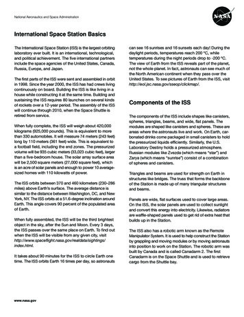
CamberDO NOT STAND ON A TRUSS THAT DOES NOT HAVE ALL ITSTRUSSSPACERS OR TEMPORARY TIES FIXED.Trusses are built with a camber in the bottom chord. The camber is designedto suit the span and load. A girder truss will have more camber than othertrusses. The camber is progressively taken up as the load from the roofcovering and ceiling is applied. Under no circumstances should trusses besupported along the span (unless designed for) by blocking or propping.The purpose of temporary bracing is to hold trusses straight and plumb priorto fixing permanent bracing. All permanent bracing, ties, hold down, etc.must be fixed prior to loading roof.If a truss has been designed to be supported internally a “SUPPORT HERE”label is affixed to the appropriate point.CODE REQUIREMENTS - Australian Standard for the installation of nailplatedtrusses AS 4440 requires that temporary ties are to be used on top chordsat spacings no greater than 3000mm and on bottom chords at spacings nogreater then 4000mm. However, it is good practice to place top chord ties ateach top chord panel point.CamberThe TrussSpacer is designed to replace the temporary chord ties as requiredby AS 4440. To conform with AS 4440 requirements use TrussSpacersas below.RT010Standard layout3000mm(max)Erection BracingTHE TRUSSES MUST BE BRACED DURING ERECTION.IF THIS IS NOT DONE, THEN TWO PROBLEMS CAN OCCUR.3000mm(max)3000mm(max)3000mm(max)RT0131. Collapse during erection.2. Erection tolerance will be exceeded, causing overloading, buckling andpossible permanent damage.The exact details of erection bracing will, for practical purposes, differ fromjob to job. The following recommendations are for guidance only as thedetails employed are the erectors responsibility.4000mm(max)The first truss should be erected straight and plumb to erection tolerancesgiven previously and temporarily braced to a rigid element, e.g. wall orground as shown on diagram x)Alternative layout3000mm(max)3000mm(max)Temporary post fixed to wall frame.One per top chord panel point.GableRT014TrussSpacers to the topof truss top chords atpanel points.4000mm(max)4000mm(max)See TrussSpacer Installation Instructions for further information.WallRT011Truss beinginstalledPreviously braced trussTrussesTrussSpacers tothe Bottom Chord.RT015Solid props fixed to groundat panel points.WallTrussSpacer: GTS600 for 600mm centres, GTS900 for 900mm centres.IMPORTANT NOTETrussSpacerThese recommendations are a guide only for the erection of standard gabletrusses up to 13000mm span, and spaced at centres not exceeding 1200mm.For trusses beyond these conditions, consult your truss fabricator.TrussSpacersErection TolerancesTrussSpacerRT012Tolerance is critical for both a good roof line and effective bracing. A stringline,a plumb line or level should be used.1. Trusses to be erected with minimal bow, in the truss and in any chord, witha tolerance not exceeding the lesser of L/200 and 50mm, where L is asdefined as shown in diagrams.2. Trusses to be erected so that no part of the truss is out of plumb with atolerance exceeding the lesser of height/50 and 50 mm.BraceTieGenerally if a bow or tilt is evident to the eye, the truss has been erectedoutside the tolerances.Brace TopTiePlateBowBraceEach successive truss should be spaced using TrussSpacers. TrussSpacersare recommended in lieu of gauging rod or timber ties, as these can be fixedto the trusses prior to lifting trusses on to top plates.PlumbTrussTrussBowLTrussIf timber ties are used, they must be continuous and be no less than 70 x 35F5. Fix to each truss with a minimum of one 65mm nail and splice the endsby lapping over two adjacent trusses. Short timber noggings between trussesare not acceptable.BowL5RETURN TO INDEXHeight ofanysectionOut ofplumbRT016
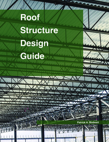
Support TolerancesTrusses parallel to non-bracing wallSUPPORT AT HEEL/CUT-OFFFix 3 nails to middle of slot.Leave gap between nailhead and bracket to allowfor vertical movement oftruss on loadingWhen truss heel or end of cut-off truss extends over support with no reducedbearing, the maximum tolerance is 50mm.Fix InternalWallBracket at1800mm crsFix 4 nailsto top plateRT017RT021Trusses at right angleto non-bracing wall50mm max.Fix InternalWall Bracketat 1800mm crsFix 3 nails to middle of slot.Leave gap between nailhead and bracket to allowfor vertical movement oftruss on loading50mm max.When truss heel or end of cut-off truss is shorter than wall support, the maximumtolerance is half the wall thickness, up to 50mm. Check bearing strength wherebearing area is reduced.Fix 4 nails to top plateINTERNALWALL BRACKET: IWB(b) Bracing WallWhen internal non-load bearing walls are designed as bracing walls, trussesshould be fixed to top plate using BraceWall Brackets according to Table 1and as follows.Trusses at right angles to bracing wallWall top plateRT018DNot greater than, 2up to 50mm max.DNot greater than, 2up to 50mm max.DDTruss at rightangle to wallFix one nail to top ofeach slot and leavegap between nailhead and bracketInternal SupportThe maximum allowable tolerance at internal support is 100mm.RT022Gap betweenwall top plateand trimmerFix 8 nailsto top plateTrusses parallel to bracing wallTruss parallel to wallRT019Wall top plateTrimmer(refer table below)100mm max.Fix one nail to topof each slot and leavegap between nailhead and bracketOverhang SupportedFor overhang supported truss, the maximum tolerance is half the wall thickness,up to 50mm. Check bearing strength where bearing area is reduced.RT023Fix trimmer totruss bottomchord with2 MSA1465MiTek screwsFix 8 nailsto top plateGap between walltop plate and trimmerBraceWall Bracket: BWB35RT020Trimmer Size(mm x mm)Minimum GradeMaximum TrussSpacing (mm)90 x 35MGP12600, 900120 x 35MGP121200DNot greater than, 2up to 50mm max.Table 1 - Fixing requirements for top of bracing wallsDFixing to Top PlateINTERNAL OR NON-LOAD BEARING WALLS.(a) Non-Bracing WallIf internal or non-load bearing walls are not designed as bracing walls,fix the truss with the InternalWall Bracket with nails to middle of slots toallow for truss settlement as it is loaded. Brackets are fixed at 1.8m centresalong unsupported sections of the wall. Where trusses are parallel to walls,trim between the bottom chords and fix brackets to the trimmer. Where nonload-bearing walls are stable in their own right, no InternalWall Bracketsare required.6Number of BraceWall Brackets 81122334452.11223444562.41223445562.7223355567For bracing walls rated at (kN/m) capacityRETURN TO INDEX
NAILING DETAILS (all truss types)(c) Non-Load Bearing External WallFor non-loadbearing external walls, such as verandah walls where trusses arepitched off verandah beams or other beams, the top plate of the wall shouldbe stabilized at maximum 3000mm centres as shown.Block piecesRT024NAILS - Use 3.05mm diameter glue coated or ring shank nails, minimum65mm long for truss thickness up to 38mm or 75mm long for truss thicknessup to 50mmBOLTS - Use M12 bolts with 50 x 50 x 3.0mm square washers or 55 dia. x 3.0mmround washers.Wall top plateFixing of blockpieces to walltop plate inaccordancewith AS1684recommendationsExternal nonload bearing wallSCREWS - Use No. 14 gauge x 65mm long up to 38mm timber or 75mm longup to 50mm timber.For further information refer to MIRS-0020.*Ensure all fasteners are fixed before loading roof.GABLE END FIXINGGap between topplate and trussThere are a number of different ways in which gable ends and verge overhangscan be constructed. These include:Truss bottomchord Cantilevered Battens Underpurlines Outriggers over Raking Truss Verge SprocketsThe selection of a particular method will depend on a number of factorsincluding verge overhang distance, roof and ceiling material, truss spacing,end wall construction, wind load and preferred local building practice andcost. The following are typical details for each fixing method. For connectiondetails refer to MIRS-0016EXTERNAL OR LOAD BEARING WALLS.Each end of the truss should be fixed to the top plate in accordance withrecommendations on page 17.FIXING TO GIRDER TRUSSESSpecial Girder Brackets are available for supporting standard trusses onthe bottom chords of Girder Trusses. These brackets should be fully fixedin accordance with details supplied by the truss fabricator prior to loadingroof. (Refer page 20).CANTILEVERED BATTENSFIXING OF VALLEY (SADDLE) TRUSSESVerge rafteror barge boardBatten overhang (or verge overhang)Connection of valley (saddle) trusses to be in accordance with detailssupplied by the truss fabricator or those in AS 4440.FIXING OF MULTIPLE PLY TRUSSESBlocking to suit@ 1200mm max centresMultiple ply trusses are required to be joined in accordance with the followingrecommendations to comply with design assumptions.Gable overhangCantilevered roof battenStandard trussRT026-aSTANDARD, TRUNCATED AND HIP TRUSSESDouble Truss (nail one side only)Join all chords and webs with nails or screws staggered one side only.*Nails or screws to be at 300mm centres for top chords and 450mm centresfor bottom chord and webs.Gable end studCeiling battenUNDERPURLINSUnderpurlin overhang (or verge overhang)CycloneTie: CT600 (typical)Fly rafterRT025-aVerge rafteror barge board300mm (T/c)450mm (B/c, web)TRIPLE TRUSS(nail both sides with bolts or screws at panel points)UnderpurlinJoin outer trusses to centre truss using the double truss details. In addition,join trusses at each panel point with one M12 bolt or alternatively with twosufficiently long No. 14 screws from each side (i.e. 4 screws at each panelpoint).Gable overhangStandard trussRT026-bGable end stud@ 600mm max. centresCeiling battenOUTRIGGERS OVER RAKING TRUSSVerge overhang (or outrigger overhang)RT025-bFly rafterM12 bolt atpanel pointsTrip-L-Grip: TGL/RVerge rafteror barge boardStandardtrussOutriggerGIRDER AND DUTCH HIP GIRDER TRUSSESNail or screw as for standard trusses except maximum nail or screw centresto be 300mm to all chords and webs.RakingtrussGable overhangRT026-cWaling plate to be fixed to each Dutch Hip girder chord and web crossing withnails, screws or bolts in accordance with M2RS-0008.Gable end stud@ 600mm max. centresIf screws are used in FastFit MkIII and MKIV Girder Bracket, use 65mm screwsin double 35mm girder. With triple 35mm ply girder, use 65mm screwsin bracket and fix additional 65mm screws in back of girder truss behindbracket. Use 3 screws for FastFit MKIII and 8 screws for FastFit MKIV GirderBracket. Alternatively, use 100mm No. 14 Type 17 hex head screws in bracket.With multiple 50mm ply girder, use bolts or longer screws.7RETURN TO INDEX15mmCeiling batten
VERGE SPROCKETSTG BCVerge sprocketlengthFly rafterTG BCThree effective flathead 65mm nailsStandard truss centresRT028-bHip BCHip BCBarge boardVerge sprocketRT026-dDetail B1 - Jack Truss to Truncated Girder TrussCycloneTie(typical)One Trip-L-Grip (TGL/R) bentto suit, with 4 MiTek 30mm x2.8mm reinforced head nailsin to the side of each top chordand 2 MiTek 30mm x 2.8mmnails to the top of truncatedgirder horizontal top chordStandard trussVerge overhangGable end stud@ 600mm max. centresCeiling battenJack TCTG HTCRT029Note: For wind classificationN2 and tile roofs, truncatedgirder with spans up to8000mm and station upto 2400mm, detail C1may be used.Hip End FixingThe fixing details in this section are suitable for trusses with maximumspacing up to 900mm (or 1200mm for sheet roof up to N3), snowload up to 0.2kPa and 3600mm maximum truncated girder station.For other applications exceeding these limits, refer to connections detailed inthe MiTek 20/20 design output.TG BCThree effectiveflat head 65mm nailsJack BCNOTES:1. These connections are adequate, based on general domestic constructionpractices which include at least two 2.5mm skew nails, with a penetrationof 10 times of nail diameter to supporting member, connecting eachmember.Detail C1 - Extended Jack or Hip Truss to top chordof Truncated Standard TrussesJack TC2. Nails details may be substituted by screws with equivalent capacity.3. These details are also applicable for use in conjunction with conventionalhip ends.TS HTCRT030For Wind Classification N1, N2, N3 or C1Connection of trusses at hip end for wind classification N1, N2, N3 or C1 arein accordance with the details shown and described in Figure 1 and DetailA1 to E1.Two 65mm skew nails into theside of each top chordFigure 1. Typical trussed hip end connection for Wind Classification N1,N2, N3 or C1Detail D1 - Jack Truss to Hip Truss (maximum jack station 1800 mm)Detail A1 or B1Detail A1 or E1Detail D1 or E1Hip TCThree effective flat head65mm nails though jacktruss top chord intohip truss top chord.Detail C1Detail B1Jack TCRT027RT031Three effective flat head65mm nails though jacktruss bottom chord intohip truss bottom chord.Hip BCJack BCNOTES:1. For effective skew nailing, the nail shall be driven into one member notcloser than 25mm to no more than 38mm from the arris in contact withthe adjacent member. The nail shall be driven at an angle between 30 and 45 to the face into which the nail is driven.Detail E1 - Jack Truss to Hip Truss (maximum jack station 3000 mm)Hip TCFix as per Detail D1 plusone CreeperConnector(CC200L/R) with6/ø2.8mm x 30mmreinforced head nailsto each top chord2. Where nails are smaller than the nominated size or other than plain shanknails, or machine driven, or both, their performance shall not be inferior tothe nail size given.3. Roof battens or purlins and ceiling battens shall be fixed to trusses inaccordance with approved specifications.Jack TCRT032Detail A1 - Hip Truss to Truncated Girder TrussHip TCTG HTCThree effective flat head65mm nails though jacktruss bottom chord intohip truss bottom chord.TG HTCRT028-aHip BCJack BCHip TCFor Wind Classification N4, C2 or C3One Trip-L-Grip (TGL/R) bent to suit,with 4 MiTek 30mm x 2.8mm reinforcedhead nails to each top chordConnection of trusses at hip end for wind classification N4, C2 or C3 arein accordance with the details shown and described in Figure 1 and DetailA2 to E2.8RETURN TO INDEX
Figure 2. Typical trussed hip end connection forWind Classification N4, C2 or C3Detail E2 or F2Detail D2Jack TCStation up to 2400mm, oneTrip-L-Grip (TGL/R) bent to suit,with 4 MiTek 30mm x 2.8mmreinforced head nails in to theside of each top chord and 2MiTek 30mm x 2.8mm nailsto the top of truncated girderhorizontal top chordDetail A2Detail C2Detail B2TG HTCRT036RT033Detail C2 - Intersection of Jack and Hip Truss to Truncated Standard TrussOne CreeperConnector(CC200L/R) with 6/ø2.8mmx 30mm reinforced headnails into each face.NOTES:1. For effective skew nailing, the nail shall be driven into one member notcloser than 25 mm to no more than 38 mm from the arris in contact withthe adjacent member. The nail shall be driven at an angle between 30 and 45 to the face into which the nail is driven.3. Roof battens or purlins and ceiling battens shall be fixed to trusses inaccordance with approved specifications.TS HTCJack TCDetail D2 - Extended Jack or Hip Truss to top chord of Truncated StandardTrusses4. Jack trusses are assumed to be supported in the horizontal top chord ofthe truncated girder.Jack TCOne Trip-L-Grip (TGL/R) bent tosuit, with 4 MiTek 30mm x 2.8mmreinforced head nails in to theside of each top chord and2 MiTek 30mm x 2.8mm nailsto the top of truncated girderhorizontal top chordDetail A2 - Hip Truss to Truncated Girder TrussHip TCOne 30 x 0.8mmStructural TieDownStrap (TD2230) with4/ø2.8mm x 30mmreinforced head nailsinto each leg.TS HTCRT038Detail E2 - Jack Truss to Hip Truss (maximum jack station 2400mm)TG HTCTG BCRT037One Trip-L-Grip (TGL/R) with4/ø2.8mm x 30mm reinforcedhead nails into the side ofeach top chord.2. Where na
timber and connections. 7. If trusses have been designed for timber fascias, do not replace with steel fascia without asking your truss supplier to check the overhang design. TRANSPORT Trusses must be fully supported when being transported in either a horizontal or vertical plane. Care must