Transcription
COMMUNICATIONS IN NUMERICAL METHODS IN ENGINEERINGCommun. Numer. Meth. Engng 2000; 00:1–6Prepared using cnmauth.cls [Version: 2002/09/18 v1.02]Quality meshing based on STL triangulations for biomedicalsimulationsE. Marchandise11 ,G. Compère1 , M. Willemet1 , G. Bricteux1 , C. Geuzaine2 , andJ-F Remacle1Université catholique de Louvain, Institute of Mechanics, Materials and Civil Engineering (iMMC),Avenue G.Lemaitre, 4 1348 Louvain-la-Neuve, Belgium2 Université de Liège, Department of Electrical Engineering and Computer Science,Montefiore Institute B28, 4000 Liège, BelgiumSUMMARYThis work describes an automatic approach to recover a high quality surface mesh from low-qualityor oversampled inputs (STL-files) obtained from medical imaging through classical segmentationtechniques. The approach combines a robust method of parametrization based on harmonic maps [1]with a recursive call to a multi-level edge partitioning software. By doing so, we are able to get ridof the topological and geometrical limitations of harmonic maps. The overall remeshing procedureis implemented, together with the finite element discretization procedure required for computingharmonic maps, in the open-source mesh generator Gmsh [2]. We show that the proposed methodproduces high quality meshes and we highlight the benefits of using those high quality meshes forbiomedical simulations. Copyright c 2000 John Wiley & Sons, Ltd.key words:biomedicalsurface mapping; surface meshing; parametrization; open source; remeshing; STL files;1. INTRODUCTIONIn the biomedical field geometrical data is acquired through medical imaging techniques suchas CT scan or MRI. The data is then usually given to end-users as a STL triangulation thatcomes as the output of a surface reconstruction algorithm applied to the point cloud obtainedfrom the medical images [3]. Those generated STL triangulations can serve as input for mostvolume meshing algorithms [4, 5]. Yet, those STL triangulations are generally oversampledand of very low quality, with poorly shaped and distorted triangles. This is still to date amajor bottleneck in the domain of biomedical computations since the quality of the meshimpacts both on the efficiency and the accuracy of numerical solutions [6, 7]. For example,it is well known that for finite element computations, the discretization error in the finiteelement solution increases when the element angles become too large [8], and the condition Correspondenceto: emilie.marchandise@uclouvain.beCopyright c 2000 John Wiley & Sons, Ltd.
2E. MARCHANDISEnumber of the element matrix increases with small angles [9]. It is then desirable to modifythe initial surface mesh to generate a new surface mesh with nearly equilateral triangles orwith a smooth gradation of triangle density based on the geometry curvature. This procedureis called remeshing.There exist mainly two approaches for surface remeshing: mesh adaptation strategies[10, 11, 12] and parametrization techniques [13, 14, 15, 16, 17, 18]. The mesh adaptationstrategies belong to the direct meshing methods and use local mesh modifications in orderboth to improve the quality of the input surface mesh and to adapt the mesh to a given meshsize criterion. The parametrization techniques belong to the indirect meshing approach. Theinitial 3D surface mesh is first parametrized onto a 2D planar surface mesh; the initial surfacecan then be remeshed using any 2D mesh generation procedure by subsequently mapping thenew mesh back to the original surface.When a parametrization of the surface is available, it is usually better to use it for remeshing.Indeed, when a parametrization is available, ensuring that the surface mesh has the righttopology is trivial. Also, as the medical geometries are often highly oversampled and of verypoor quality, the numerous sampling operations are much more efficient in the parameter planethan in 3D space.In a recent paper [1] we have introduced an efficient approach for high quality remeshingof surfaces based on a parametrization technique. The approach uses a discrete finite elementharmonic map to parametrize the input triangulation onto a unit disk. By combining it witha local cavity check algorithm that enforces the discrete harmonic map to be one-to-one, wecame out with a robust method for remeshing that is advantegeous compared with meshadaptation methods. However, as it was highlighted in [1], there are two important limitationsof harmonic maps, namely limitations on the genus and the geometrical aspect of the surface.Indeed, to be able to parametrize the triangulation onto a unit disk, the triangulation shouldbe homeomorphic to a disk, i.e have a genus zero with at least one boundary. Besides, as thesolution of harmonic maps tends exponentially to a constant, the triangulation should have auniform geometrical aspect ratio to prevent non distinguishable coordinates.In this paper, we present a robust and automatic way to overcome the topological andgeometrical limitations of harmonic maps. The presented algorithm combines a discreteharmonic mapping with a multi-level edge partitioning software that recursively partitionsthe triangulation into a small number of charts that satisfy the topological and geometricalconstraints. We show that our method renders high quality meshes and highlight the benefitsof using those high quality meshes for cardiovascular and bone biomechanical simulations.2. MESHING WITH HARMONIC MAPSThe key feature of our remeshing algorithm presented in [1] is to define a map that transformscontinuously a surface S R3 into a unit disk S 0 embedded in R2 [19, 20]. The parametrizationshould be a bijective function u(x):x S R3 7 u(x) S 0 R2 .Copyright c 2000 John Wiley & Sons, Ltd.Prepared using cnmauth.cls(1)Commun. Numer. Meth. Engng 2000; 00:1–6
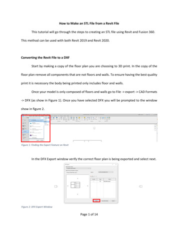
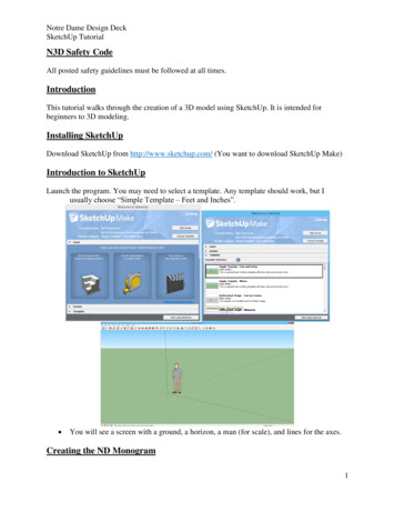
QUALITY MESHING BASED ON STL TRIANGULATIONS FOR BIOMEDICAL SIMULATIONS3Such a parametrization exists if the two surfaces S and S 0 have the same topology, i.e are bothzero genus surfaces (G 0) and have at least one boundary (NB 1)† . When the surface Sis a triangular mesh as in the case of an STL file, the genus can be easily computed from theEuler-Poincare formula: NV NE NT 2 NBG .(2)2where NV , NE , and NT are respectively the number of vertices, edges and triangles.Harmonic maps have been chosen for the parametrization [21, 22], by solving one Laplaceproblem for each coordinate: 2 u 0, 2 v 0,(3)with appropriate Dirichlet boundary condition for one of the boundaries S1 of the surface S,u(l) cos(2πl/L) , v(l) sin(2πl/L),(4)and with Neumann boundary conditions for the other boundaries. In (4), l denotes thecurvilinear abscissa of a point along the boundary S1 of total length L.The discrete harmonic map is obtained through a finite element formulation of the Laplaceproblem (3)–(4) on the STL triangulation. The finite element solutions provide to each internalvertex of the original triangulation x its local coordinates u and v. However, as shown in [1] thesolution of the mapping becomes exponentially small‡ for vertices located away from S1 . Asa consequence, local coordinates u and v of those far away vertices might numerically becomeindistinguishable (see the zoom in Fig.1). To prevent this, the geometrical aspect ratio of thesurface:Hη (5)Dshould be smaller than 4. Indeed we can show that η 4 corresponds to an area of mappedtriangles of about ri2 10 10 (see Eq. 23 and Fig. 10c in [1]). In (5), H is the maximal distance(computed on the 3D surface S) of a mesh vertex to the boundary S1 and D is the equivalentdiameter of the boundary S1 .Figure 1 shows both an initial triangular mesh of S and its map onto the unit disk. Thesurface S results from the segmentation of an anastomosis site in the lower limbs, more preciselya bypass of an occluded femoral artery realized with the patient’s saphenous vein. The unitdisk D contains two holes that correspond to the boundary of the femoral artery S2 and thesaphenous vein S3 on which we have imposed Neumann boundary conditions.Once the parametrization is computed, we use standard 2D anisotropic mesh generationprocedures onto the unit disk, with the aim of producing a mesh in the real 3D space that hascontrolled element sizes and shapes. In order to control the surface element sizes, we define anisotropic mesh size field [2] δ(x) that is a function that gives the optimal mesh edge length atpoint x. In the examples that will be presented, the mesh size field is chosen to be either aconstant or varies according to the curvature of the geometry.† Forexample, a sphere has G 0 and NB 0 and a torus has G 1 and NB 0.principle, the solution becomes constant far from the boundary, this constant being the average of thesolution on the boundary. Yet, the average of the solution on the boundary being zero, the solution goes tozero far from the boundary.‡ InCopyright c 2000 John Wiley & Sons, Ltd.Prepared using cnmauth.clsCommun. Numer. Meth. Engng 2000; 00:1–6
4E. MARCHANDISEfemoral artery S2vsaphenous vein S3umiller cuffStarting vertexZoompopliteal arterySharmonic mapzxy S1Starting vertex Ms0Figure 1. STL triangulation of an arterial anastomosis (G 0, NB 3, η 5) and its map onto theunit circle (left) and mapped mesh on the unit circle (right). As the geometrical ratio of the initial STLtriangulation is higher than 4, the mapped triangles become very small (see zoom) in the parametricunit disk.3. AUTOMATIC QUALITY REMESHINGIn the previous section we put to the fore the topological and geometrical limitations ofharmonic maps. To sum up, for the proposed discrete harmonic maps we need:i ) G 0;ii ) NB 1;iii ) η 4.The first condition can be verified using Eq. (2); the second condition can be checked bylooking simply at the topology of the mesh. The third condition is less trivial to assess.In the computer graphics community, people overcome all three conditions simultaneouslyby using a partition scheme based on the concept of Voronoi diagrams [22] or inspired byMorse theory [18, 23]. The resulting mesh partitions are area-balanced patches that satisfythe three conditions. However, this approach results in a large number of patches and hence alarge number of interfaces between those patches, which is not desirable.We propose in this paper a fast and automatic way to overcome both topological andgeometrical limitations of harmonic maps. The idea is to combine an harmonic map witha multilevel edge partitioning softwares such as Chaco [24] or Metis [25] to partitionrecursively the triangulation into a minimal number of partitions that satisfy the topologicaland geometrical conditions. Multilevel methods are attractive since they reduce the costs ofspectral partitioning methods while still generating high quality partitions. These work onCopyright c 2000 John Wiley & Sons, Ltd.Prepared using cnmauth.clsCommun. Numer. Meth. Engng 2000; 00:1–6
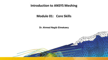
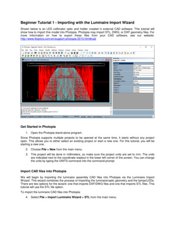
QUALITY MESHING BASED ON STL TRIANGULATIONS FOR BIOMEDICAL SIMULATIONS5the connectivity graph of the mesh, but instead of trying to split this directly, the graph isfirst condensed through a number of levels. The condensation is achieved through clusteringtogether vertices that are close together’ to produce a graph with fewer vertices. New edgesbetween the clusters are weighted to reflect the number of edges that existed in the largergraph. By using several levels of condensation a much smaller graph can be obtained that iseasily partitioned by a method such as spectral bisection. This partitioning information canthen be transfered up through the levels to the original graph.The automatic procedure for a uniform remeshing a triangulation S with prescribed meshsize δ is illustrated in Figures 2 and 3 and reads as follows:1. Check conditions (i)-(iii). If those conditions are not satisfied, recursively split the meshwith the multi-level partitioning software until satisfied. The geometrical aspect ratio ηis computed approximately by using the ratio between the maximal size of the boundingbox of the mesh partition and the maximal size of the bounding box of the boundaries S of the mesh partition [26] (see illustration in Fig. 3(1)) ;2. Remesh the lines that are the boundaries of the triangulation and the interfaces betweenthe mesh partitions (see the interfaces between colored patches in 2a) that are representedby highlighted white lines in Fig.2b); Those lines are defined as model edges and dividedRLinto N parts as follows: N 0 x,t /δdt. The remeshed lines are embedded in thefinal mesh shown in Fig. 2c).3. Compute the harmonic mapping for every mesh partition as explained in the previoussection. If the boundary is composed of several parts Si , assign the Dirichlet boundaryconditions (4) to the closed boundary that has the largest bounding box.4. Use standard surface meshers to remesh every partition in the parametric space and mapthe triangulation back to the original surface.5. If a volume mesh is needed, generate a volume mesh from the new surface mesh usingstandard volume meshing techniques.In our algorithm, the bounding boxes are oriented bounding boxes that are computed withthe fast Oriented bounding box HYBBRID optimization algorithm presented in [26] whichcombines the genetic and Nelder-Mead algorithms [27].The automatic procedure is implemented within the open source mesh generator Gmsh [2].We show a simple example of how to use it. We suppose that we have an initial surface meshand write the following geometry file ”remesh.geo”://Merge the STL triangulationMerge "skull.stl";// Remesh the edges (if any), and faces with the presented algorithmCompound Surface(100) {1};// Create a volume and mesh given the new surface meshSurface Loop(2) {100};Volume(3) {2};Copyright c 2000 John Wiley & Sons, Ltd.Prepared using cnmauth.clsCommun. Numer. Meth. Engng 2000; 00:1–6
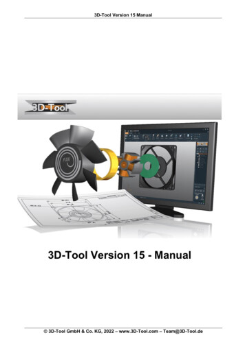
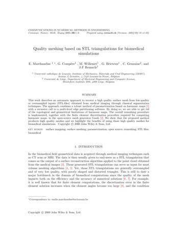
6E. MARCHANDISEa)b)c)Figure 2. Remeshing algorithm. a) Initial triangulation (G 2, NB 0) that is cut into differentmesh partitions of zero genus, b) Remesh the lines at the interfaces between partition, c) Computeharmonic map for every partition and remesh the partition in the parametric space (u(x) coordinatesvisible for one partition).DHa)b)c)Figure 3. Remeshing algorithm. a) Initial triangulation (G 0, NB 3, η H/D 16) that is cut intodifferent mesh partitions of uniform geometrical aspect ratio, b) The harmonic map is computed forevery partition (u(x) coordinates visible for one partition) c) Remesh every partition in the parametricspace. The mapped initial triangulation is shown for the partition visible on the middle image.Other examples can be found on the Gmsh wiki: https://geuz.org/trac/gmsh (username:gmsh, password: gmsh) .Copyright c 2000 John Wiley & Sons, Ltd.Prepared using cnmauth.clsCommun. Numer. Meth. Engng 2000; 00:1–6
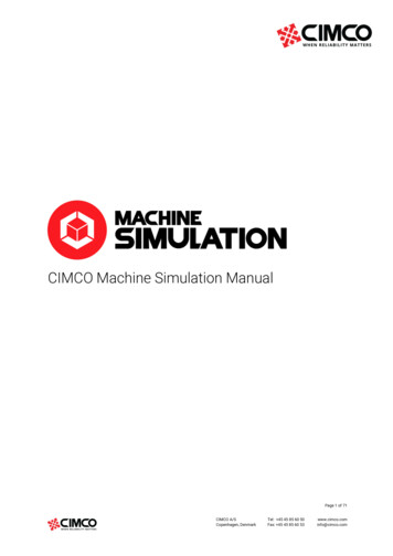
QUALITY MESHING BASED ON STL TRIANGULATIONS FOR BIOMEDICAL SIMULATIONS74. RESULTS4.1. High quality surface and volume meshesWe have run our computational algorithm on a variety of medical geometries of arbitrary genusand complexity. Fig. 4 illustrates a uniform remeshing of respectively a skull, an upper jawand a hemipelvis. The top figure shows the remeshing of a human skull, the middle figuresthe remeshing of an upper jaw that is oversampled (116k vertices) and the lower figures theremeshing of an initial poor quality mesh of an hemi-pelvis. None of those initial triangulationssatisfy the topological conditions: the skull has genus G 2, the jaw has genus G 0 but hasNB 0 and the pelvis has G 1 and NB 0.The quality of an isotropic mesh is evaluated by computing the aspect ratio of every meshtriangle as follows [2]:κ αsin â sin b̂ sin ĉinscribed radius 4,circumscribed radiussin â sin b̂ sin ĉ(6)â, b̂, ĉ being the three inner angles of the triangle. With this definition, the equilateral trianglehas κ 1 and degenerated (zero surface) triangles have κ 0.Fig. 5 shows the quality histogram for the initial triangulation of a foot and the remeshedgeometry. As seen in fig.5, the mean κ̄ and minimum quality κmin of the new mesh are both veryhigh: κ̄ 0.94, κmin 0.62. This mean quality measure was found to be constant ( 2%) forall examples and hence independent of the initial triangulation and the mesh density. Volumetetrahedral meshes can then be created from those surface meshes. In order to measure thequality of the tetrahedral elements, we define another quality measure γ based also on theelement radii ratio [2, 28]: 6 6Vγ ,SF LEV being the volume of the tetrahedron, SF being the sum of the areas of the 4 faces of thetetrahedron, and LE being the sum of the lengths of the 6 edges of the tetrahedron. This γquality measure lies in the interval [0, 1], an element with γ 0 being a sliver (zero volume).When creating volume meshes from surfaces that have been remeshed with our algorithm,we obtain also quite constant γ qualities, i.e γmin 0.25 10% and γ̄ 0.7 10%. Thisis much better than the gamma quality of volumes meshes created from STL triangulations.Indeed the quality of those volume meshes is often very poor, with elements being small sliversγmin 1.e 5 that will hinder or event prevent the convergence of the numerical method.The time necessary to generate with our algorithm a new surface mesh less is less than 100 sfor 106 elements.4.2. Quality meshing for biomedical simulationsThe two first biomedical simulations concern blood flow simulations. In the first example,blood flow in a distal anastomosis of a bypass is considered. While this problem has oftenbeen studied in-vitro in simplified geometries [?, ?, ?], the simulation of blood flow in invivo complex geometries is of great interest when one wants to focus on the patient-specificaspect [?]. As this is not the goal of this study, we refer the reader to the cited referencesfor detailed hemodynamical analysis. We intend to illustrate in the following test case that inCopyright c 2000 John Wiley & Sons, Ltd.Prepared using cnmauth.clsCommun. Numer. Meth. Engng 2000; 00:1–6
8E. MARCHANDISEFigure 4. STL triangulations obtained from medical images (Left) that have been automaticallyremeshed with our automatic remeshing algorithm (Right).real and complex geometries, a high-quality mesh is required in order to ensure the numericalconvergence of the simulation. Identical conclusions have been reached in computational studiesrelated to other biomedical applications and considering the effects of various meshing style:Vinchurkar et al [?, ?] have shown the performances of different types and qualities of meshes inCopyright c 2000 John Wiley & Sons, Ltd.Prepared using cnmauth.clsCommun. Numer. Meth. Engng 2000; 00:1–6
FrequencyQUALITY MESHING BASED ON STL TRIANGULATIONS FOR BIOMEDICAL dRemeshed00.20.40.6Aspect ratio0.81Figure 5. Plot of the quality histogram of both the STL triangulation and the remeshed surface of ascanned foot.the complex branching geometries of the respiratory system; Liu et al [?] compared simulationsin the total cavopulmonary connection using structured and unstructured meshes; Ethier andPrakash [?] studied a mesh convergence study of blood flow in a coronary artery model.In the two following test cases, blood flow is governed by the incompressible Navier-Stokesequations for a Newtonian fluid. We use an implicit pressure stabilized finite element methodthat has been shown to be robust, accurate and stable [29]. The linearized system is solvedby using a GMRES solver with a relative convergence tolerance of 10 12 . The fluid propertiesof blood are taken to be ρ 1060 kg/m3 for the density and µ 3.5 P a.s for the dynamicviscosity.The first test case studies steady blood flow at Reynolds Re 900 (based on the inletdiameter and average inlet velocity) in a veinous anastomosis of an occluded femoral artery(Figure 6) [30]. The anastomosis is segmented out of raw image data from a patient thatunderwent lower-limb bypass surgery. Two surface meshes are produced, one from the initialSTL triangulation and one using the remeshing procedure based on harmonic maps. Thosesurface meshes then serve as input for the generation of two volume meshes of about 104tetrahedra (an STL based and a remeshed based volume mesh). Table I shows the quality ofthese two surface and volume meshes: the remeshed mesh presents higher minimal and meanqualities that enables the flow solver to converge better (see Fig. 6).MeshSTLRemeshedSurface qualityκminκ0.0033 0.8210.6400 0.949Volume qualityγminγ0.0019 0.5630.2550 0.677Table I. Quality of the surface and volume meshes.The simulation is run with a constant flow rate at the inlet (Q 75 ml/min), a no-slipboundary condition at the walls and a constant pressure boundary condition on the outletCopyright c 2000 John Wiley & Sons, Ltd.Prepared using cnmauth.clsCommun. Numer. Meth. Engng 2000; 00:1–6
10E. MARCHANDISEResidualsurface (p 50 mmHg). Figure 6 shows the convergence rates for each of the two volumemeshes. Figure 6 shows that the element quality has a significant impact on the convergencerate of the solution procedure. Indeed, the simulation on the mesh obtained from the STLconverges at 1.e 7 , while the remeshed mesh gives results that are two times more LRemeshed0510 15 20 25 30 35 40Nb of iterationsFigure 6. Blood flow simulation in an arterial bypass. The left figure shows the streamlines (zoomnear the anastomosis) and the right figure shows the residual decrease for the two different volumemeshes.The next example studies the flow in a simplified aortic arch. The STL triangulation wasfound on the INRIA web site§ . Accurate and converged numerical simulations are mandatorysince it has been shown that the flow patterns and the locations of low wall shear stress (WSS)correspond with locations of aneurysm formation in the descending aorta [31, 32]. The wallshear stress is defined as the norm of the shear stress at the wall: W SS k tw k k t ( t · n) · n)k, with t µ u uT · n.(7)For the numerical simulation, we apply simple boundary conditions: a parabolic velocityprofile at the inlet (heart) and zero natural pressure boundary conditions at the outlets(innominate artery, left common carotid artery, left subclavian artery and descending aorta)and a zero velocity (no-slip) on the vessel walls. We consider a stationary flow at ReynoldsRe 450 and different meshes: isotropic volume meshes of respectively 28K, 160K and 466Ktetrahedra and an adapted anisotropic mesh that has approximately 20K. We fist computean isotropic surface mesh with our remeshing algorithm and then produce two different typesof volume meshes: (i) isotropic volume meshes of different prescribed mesh sizes, (ii) adaptedanisotropic volume meshes and (ii) a boundary layer mesh obtained by extrusion of the surfacemesh over a number of layers (5 layers in the boundary δ 1/ Re). Adaptive refinement inthe boundary with either anisotropic metric fields or boundary layers is indeed attractive[34, 35, 36] to increase the solution accuracy in the region of interest (at the wall) and§ ght c 2000 John Wiley & Sons, Ltd.Prepared using cnmauth.clsCommun. Numer. Meth. Engng 2000; 00:1–6
QUALITY MESHING BASED ON STL TRIANGULATIONS FOR BIOMEDICAL SIMULATIONS11this way decrease the load on the solver by reducing the number of finite elements used.With the presented approach of harmonic map, we do have a parametric description of theinitial triangulation that enables us to use anisotropic mesh adaptation libraries such as ouropen source MadLib library [33]. This library aims at modifying the initial mesh to make itcomply with criterions on edge lengths and element shapes by applying a set of standard meshmodifications (edge splits, edge collapses and edge swaps, .). An anisotropic field based on thedistance to the wall and the curvature can then be defined in order to generate boundary layermeshes. In the example presented in Fig.7c), we prescribe a small size with a linear growthin the normal direction to the wall, and three times a larger size is prescribed in the tangentdirections. The final mesh metric field is built from those resulting sizes and directions. Itshould be noted that a volume mesh was also produced from the STL triangulation but thisvolume mesh was of too low quality to obtain a convergence of the numerical simulation(γmin 1.5e 5 and γ̄ 0.45).Figure 7 shows the initial STL triangulation, a remeshed isotropic surface mesh, and a meshcut of the volume anisotropic mesh. As can be seen, initial STL triangulation is faceted andthe horizontal structure of the CT slices are visible.ı̈¿ 12ı̈¿ 12Viewb),c)View b),c)a)b)c)Figure 7. Aortic arch meshes: a) Initial STL triangulation (top) and remeshed surface (isotropic meshsize), b) Anisotropic volume mesh cut created from the remeshed surface with MAdLib, c) Boundarylayer volume mesh.Copyright c 2000 John Wiley & Sons, Ltd.Prepared using cnmauth.clsCommun. Numer. Meth. Engng 2000; 00:1–6
12WSS [Pa]E. MARCHANDISE0.60.50.40.30.20.10Uniform 28KUniform 466KUniform 1.4MAnisotropic 20KBoundary Layer 50K050100 150 200 250 300 350Angle [Deg]Figure 8. Blood flow simulation in an aortic arch. The left figure shows the WSS distribution and theright figure the WSS along the circumference at section A A0 for different meshes for a constantinlet flow rate. The zero angle corresponds to the location A0 .Figure 8 shows the WSS values computed for different meshes at section A A0 . We selectedsection A A0 since this section intersects the regions of low and high WSS. For this section,the WSS values vary in the azimuthal direction, the zero angle corresponding to the locationA0 . As can be seen in Fig.8, the high quality isotropic volume meshes converge well towards anazimuthal WSS distribution. The WSS for the anisotropic mesh exhibits more numerical noisethat is due to the velocity gradient computations involved in (7) that are less accurate for highlyanisotropic meshes [34, 35, 36]. Meanwhile, the mean values (max and min WSS) convergetowards the one obtained with the finest isotropic mesh within a smaller computational time(mesh of only 20K). The boundary layer volume mesh provides less oscillatory results andshow also convergence towards the finest isotropic mesh for a reduced number of elements(50k versus 1.4M tetrahedra).The last biomedical computation is the stress computation on a hemipelvis. The initialtriangulation (STL file) of the pelvic bone is obtained from a segmentation procedure of asawbone model that was scanned (CT scan with 1.25 mm thickness). Several isotropic surfacemeshes are obtained with our automatic remeshing algorithm for different mesh refinements.We analyze the influence of the mesh quality on the accuracy of the solution : 5 meshesobtained with the uniform remeshing algorithm having respectively 420k, 270k, 70k, 20k and5k triangles, 2 meshes that are adapted to the curvature with 54k and 8k triangles and 3 STLtriangulations of 10k, 5k and 2k triangles (see Fig. 9). The 3 different STL files are obtainedwith the meshLab software by refining the triangles or collapsing the edges of the initial STLfile of 5k triangles. As expected, the mean quality is κ̄ 0.94 for the remeshed pelvis whileκ̄ 0.66 for STL triangulations. The curvature adapted meshes are computed by defining themesh size δ as follows:2πR1, with R (8)δ Npκwhere κ is the curvature that is computed from the initial nodes of the STl triangulation withthe algebraic point set surface (APSS) method that is based on the local fitting of algebraicCopyright c 2000 John Wiley & Sons, Ltd.Prepared using cnmauth.clsCommun. Numer. Meth. Engng 2000; 00:1–6
QUALITY MESHING BASED ON STL TRIANGULATIONS FOR BIOMEDICAL SIMULATIONS13spheres [?] and Np is the number of points chosen for the radius of curvature (Np 15).Viewb,ca)b)c)Figure 9. Different meshes used for the mesh convergence analysis. a) Triangulation on which acurvature κ is computed, b) isotropic remeshed pelvis (δ 0.1) and c) Curvature-dependent remeshedpelvis (δ given by Eq.(8)).Figure 10 shows the boundary conditions used for the finite element computation. The finiteelement model is constrained at the sacro-iliac joint and a symmetry boundary condition isapplied on the pubic-symphysis. The pelvis is subjected to a 3D load case representative ofa single leg stance. Taking a body weight equal to 1000N, the resulting surface traction forceacting on the acetabulum surface is 0.7 M P a. As different meshes are used, the elementsforming the boundaries are selected inside a sphere (for the acetabulum and the sacrum) andon one side of a plane (for the pubis) intersecting the pelvis. These fixed boundary conditionsare more representative of in vitro experimentation than in vivo environment but are realisticenough for this analysis [37].In order to put to the fore the effect of the surface mesh on the behavior of the numericalsolution, we analyze the stresses in the cortical bone by using shell elements on the surfaceof the pelvis. This is well adapted for this analysis because the pelvis has a cortical shellthat undergoes most of the stresses. We model this cortical surface layer with a homogeneousshell section of uniform thickness 2mm, an isotropic Young modulus E 18000N/mm2 anda poisson ratio of ν 0.3 [38, 39].The simulations are computed wih the finite element solver Abaqus with linear finiteelements. Figure 11 shows the distribution of the Von-Mises stresses developed in the corticalbone with the finest isotropic mesh. The stresses are concentrated around the cotyle and towardthe fixed boundary condition at the sacro-iliac joint. The maximum stresses are obtainedaround the cotyle for the fine meshes while the STL meshes produce higher stresses locatedabove the illium. These are local stress concentrations that
The data is then usually given to end-users as a STL triangulation that comes as the output of a surface reconstruction algorithm applied to the point cloud obtained from the medical images [3]. Those generated STL triangulations can serve as input for most volume meshing algorithms [4,5]. Yet, those STL triangulations are generally oversampled