Transcription
CIMCO Machine Simulation ManualPage 1 of 71CIMCO A/SCopenhagen, DenmarkTel: 45 45 85 60 50Fax: 45 45 85 60 53www.cimco.cominfo@cimco.com
ContentsIntroduction to CIMCO Machine Simulation. 4Geometry Manager . 51.2.Machine Origin . 7Work Offsets . 8Stock . 93.4.5.6.7.Importing an External STL. 10Manually Defining the Stock – Cylinder . 12Manually Defining the Stock – Box . 14Automatically Scanning a Stock . 16Exporting Stock STL . 18Simulation Report . 198. Collisions . 209. Limits . 2210.Collision Settings . 24Navigation . 2511.12.Path to Current Template . 26Setup Structure . 27Scanning Commands . 2913.14.15.16.Scanning Mode . 30Read/Write Settings. 31NC File Placement Settings . 32Sample Scanning Commands. 33Downloading Machines . 36Machine Configuration Editor . 3817.18.19.20.21.22.23.Add a Linear Axis . 42Add a Rotary Axis. 43Add Geometry . 44Tool Change Position . 45Saving a Machine Configuration . 46Deleting a Machine Configuration . 47Machine Configuration Error Notifications . 48Specifying Default Machine Configurations for NC Programs . 49Simulation Interface. 51Backplot Tab . 52Page 2 of 71CIMCO A/SCopenhagen, DenmarkTel: 45 45 85 60 50Fax: 45 45 85 60 53www.cimco.cominfo@cimco.com
24.25.26.27.File . 52View . 53Toolpath . 56Tool . 5727.1.Tool Setup . 5828.Solid . 6929.Other . 7030.Find . 71Page 3 of 71CIMCO A/SCopenhagen, DenmarkTel: 45 45 85 60 50Fax: 45 45 85 60 53www.cimco.cominfo@cimco.com
Introduction to CIMCO Machine SimulationCIMCO Machine Simulation is an add on to CIMCO Edit. CIMCO Machine Simulation is used forsimulating the manufacturing process of a workpiece within a machine environment. Thesimulation allows you to observe the toolpath and highlights all collisions or out of limit movesfound within the CNC program. CIMCO Machine Simulation can be accessed by clicking on theicon in the Backplot tab.In CIMCO Machine Simulation, the CNC program is displayed in the left pane of the window. Thesimulation is shown in the centre and the Geometry Manager, Navigation and Simulation Reportcan be found in the right pane.Video link: Introduction to CIMCO Machine Simulation (https://youtu.be/RvTXRH2SZoE)Page 4 of 71CIMCO A/SCopenhagen, DenmarkTel: 45 45 85 60 50Fax: 45 45 85 60 53www.cimco.cominfo@cimco.com
Geometry ManagerThe Geometry Manager can be used for defining a machine, specifying work offsets, determiningthe machine origin, adding stock, and importing workpiece and fixtures. The Geometry Managercontains the elements described below.Page 5 of 71CIMCO A/SCopenhagen, DenmarkTel: 45 45 85 60 50Fax: 45 45 85 60 53www.cimco.cominfo@cimco.com
Shows head of machine and all additional axis that are applied.Right-clicking this icon allows for machine parts to be added and setting visibility.Shows the table of the machine and all additional axis that are applied.Right-clicking this icon allows for machine parts to be added and setting visibility.Shows the base of the machine and all additional axis that are applied.Right-clicking this icon allows for machine parts to be added and setting visibility.Shows that a workpiece has been added to the simulation. The workpiece can beadded by right-clicking on any of the axis lines located within the Geometry Manager.Identifies the axis that will have a linear movement during the machine simulation.Identifies the axis that will have a rotary movement during the machine simulation.Page 6 of 71CIMCO A/SCopenhagen, DenmarkTel: 45 45 85 60 50Fax: 45 45 85 60 53www.cimco.cominfo@cimco.com
1. Machine OriginThe Machine Origin is a fixed point that can be set within the ‘Machine Origin’ parameters. Thework offsets, stock and fixture/workpiece can be positioned according to the Machine Origin.Specify the machine origin by clicking on ‘Origin’. A properties section will appear below and theoption to specify the machine origin will be possible through ‘Translation’. Values can be inputcorresponding to the X, Y and Z coordinates.Page 7 of 71CIMCO A/SCopenhagen, DenmarkTel: 45 45 85 60 50Fax: 45 45 85 60 53www.cimco.cominfo@cimco.com
2. Work OffsetsSpecify the work offset clicking on the work offset number that has been generated by the NCprogram. A properties section will appear below and the option to determine the work offset willbe possible through ‘Translation’. Values can be input corresponding to the X, Y and Zcoordinates.Copy and Paste a position between work offsets/workpiece and fixture/stock.Page 8 of 71CIMCO A/SCopenhagen, DenmarkTel: 45 45 85 60 50Fax: 45 45 85 60 53www.cimco.cominfo@cimco.com
StockStock can be added through the Geometry Manager. Stock removal simulates the removal ofmaterial based on the NC code. There are multiple options to create the stock, including theability to import an external STL, manually define the stock (Cylinder/Box) and also enableautomatic scanning that reads a specified value directly from the NC code and adds a stockbased on those values.Video link: Stock Removal tutorial (https://youtu.be/DlCt1l31jMk)Page 9 of 71CIMCO A/SCopenhagen, DenmarkTel: 45 45 85 60 50Fax: 45 45 85 60 53www.cimco.cominfo@cimco.com
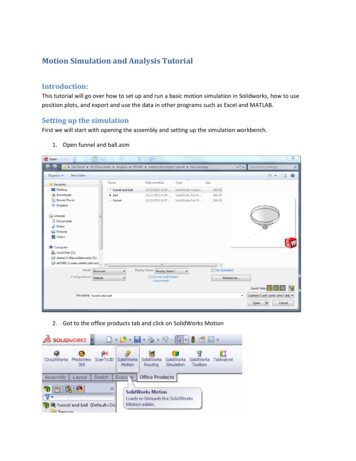
3. Importing an External STLTo import an external STL, right-click in the Geometry Manager and select 'Add stock' ‘STL’.Select the STL file from its saved location and select ‘Open’.A 'Solid Setup' dialog will appear. Collision checking and render quality can be set here. Thisdialog will show when using either one of the options to add a stock. Select the checkbox 'Stop if tool collision detected (rapid through stock)' to enable thesimulation to stop if it detects a rapid move through the stock. Select the checkbox 'Stop if tool holder collision detected' to enable the simulation tostop if it detects a collision between the tool holder and stock. Move the cursor to 'Low Quality (Fast)' for a fast rendering but of low quality. Move the cursor to 'Medium Quality' for a standard rendering of standard quality. Move the cursor to 'High Quality (Slow)' for a slow rendering but of high quality.Page 10 of 71CIMCO A/SCopenhagen, DenmarkTel: 45 45 85 60 50Fax: 45 45 85 60 53www.cimco.cominfo@cimco.com
Select 'Stock' in the Geometry Manager to see its 'Properties'.'Properties' is located below the Geometry Manager. In the Properties section specify the position of thestock by editing the values within 'Translation' and 'Rotation'.Determine the origin of the stock by clicking on the dropdown menu beside the 'Origin' section.The stock setup can be saved by right-clicking in the Geometry Manager and select 'Save Setup'.Page 11 of 71CIMCO A/SCopenhagen, DenmarkTel: 45 45 85 60 50Fax: 45 45 85 60 53www.cimco.cominfo@cimco.com
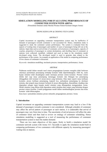
4. Manually Defining the Stock – CylinderTo manually define a cylinder stock, right-click in the Geometry Manager and select 'Add stock' ‘Cylinder’.Select 'Stock' in the Geometry section to open its properties.'Properties' is located below the Geometry Manager. In the properties section, edit the stockdimensions and the position of the stock by editing the values within 'Translation'. Determine thestocks 'Diameter', 'Height' and 'Axis'.Page 12 of 71CIMCO A/SCopenhagen, DenmarkTel: 45 45 85 60 50Fax: 45 45 85 60 53www.cimco.cominfo@cimco.com
Determine the origin of the stock by clicking on the dropdown menu beside the 'Origin' section.When changes are made to the stock’s dimensions or position, a wireframe stock will appear inthe backplot window providing a preview of the newly defined stock.When the stock is setup correctly, locate and select the 'Zoom/Regenerate' solid tab. The fullydefined stock will now appear in the backplot window.Once the stock is fully defined and the setup is correct, you can save the setup. Right-click in theGeometry Manager and select 'Save Setup'.Page 13 of 71CIMCO A/SCopenhagen, DenmarkTel: 45 45 85 60 50Fax: 45 45 85 60 53www.cimco.cominfo@cimco.com
5. Manually Defining the Stock – BoxTo manually define a stock box, right-click in the Geometry Manager and select 'Add stock' ‘Box’. Determine whether the stock will be defined using 'Dimensions' or by its 'Min/Max' values.Page 14 of 71CIMCO A/SCopenhagen, DenmarkTel: 45 45 85 60 50Fax: 45 45 85 60 53www.cimco.cominfo@cimco.com
Select 'Stock' in the Geometry section to open its properties.'Properties' is located below the Geometry Manager. In the properties section, edit the stockdimensions and the position of the stock by editing the values within 'Translation'.If the stock is determined by its Min/Max values, specify where the stock values are relative to byselecting the drop-down menu beside 'Relative To'. There are two options, 'Absolute' or'Toolpath'.To edit the stock dimensions the user can edit the values within the 'Lower Corner' and 'UpperCorner'.When the stock is setup correctly, locate and select the 'Zoom/Regenerate' solid tab.Page 15 of 71CIMCO A/SCopenhagen, DenmarkTel: 45 45 85 60 50Fax: 45 45 85 60 53www.cimco.cominfo@cimco.com
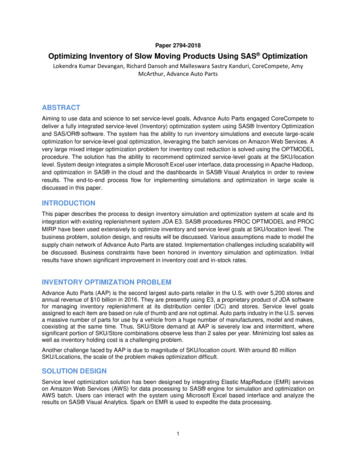
6. Automatically Scanning a StockInput the 'Box - Min/Max' stock scanning command into the NC file using the following format.( STOCK MIN X0 Y0 Z0 )( STOCK MAX X0 Y0 Z0 )Input the 'Box - Dimensions' stock scanning command into the NC file using the following format.( STOCK RECTANGLE X-279.927 Y-232.1 Z-243.6 W 220 L 286 H 160 ORIGIN "TOP" )Input the 'Cylinder' stock scanning command into the NC file using the following format.( STOCK CYLINDER X-279.927 Y-232.1 Z-243.6 D 360 H 160 ORIGIN "TOP" AXIS "Z" )Input the 'STL' stock scanning command into the NC file using the following format.(STOCK STL X-279.0 Y-264.0 Z-343.6 PATH "C:\Users\fletc\Desktop\Haas UMC-750\5XDemopart Stock.stl" ORIGIN "TOP" )Page 16 of 71CIMCO A/SCopenhagen, DenmarkTel: 45 45 85 60 50Fax: 45 45 85 60 53www.cimco.cominfo@cimco.com
Locate and select the ‘Global Setup’ tab and select ‘Scanning’. In scanning mode choose ‘Scanactive nc file’. In Read/Write settings, tick the box beside ‘Read’ to automatically read itsdescription from the nc or setup file. Tick the box beside ‘Write’ to automatically write thedescription into the nc or setup file if any changes are made.The stock will be scanned directly into the backplot window.Page 17 of 71CIMCO A/SCopenhagen, DenmarkTel: 45 45 85 60 50Fax: 45 45 85 60 53www.cimco.cominfo@cimco.com
7. Exporting Stock STLExport a Stock as STL by right-clicking the stock in the Geometry Manager and selecting ‘SaveSTL file’.A window will open allowing the destination directory to be chosen. Input the STL name, selectthe directory and click ‘Save’. Note: The position in the program that the stock is exported willcorrespond with the condition of the STL file.Page 18 of 71CIMCO A/SCopenhagen, DenmarkTel: 45 45 85 60 50Fax: 45 45 85 60 53www.cimco.cominfo@cimco.com
Simulation ReportThe Simulation Report provides information about collisions and limits. The Simulation Reportallows you to view all Collisions and outer Limit movements detected within the CNC program.By clicking on any of the detected collisions or limits, the corresponding line within the CNCprogram will highlight. When the line causing the collision or outer limit is corrected, theSimulation Report will automatically update, removing the collision or outer limit.To view the Simulation Report, click on the Simulation Report tab located to the left of theGeometry Manager tab.Page 19 of 71CIMCO A/SCopenhagen, DenmarkTel: 45 45 85 60 50Fax: 45 45 85 60 53www.cimco.cominfo@cimco.com
8. CollisionsClick on the iconto reveal a list of all the Collisions that have been detected.Click on any Collision to highlight the corresponding line in the CNC program. The highlighted linecan then be adjusted, and the Simulation Report will automatically update, removing the collisionfrom the Simulation Report.Page 20 of 71CIMCO A/SCopenhagen, DenmarkTel: 45 45 85 60 50Fax: 45 45 85 60 53www.cimco.cominfo@cimco.com
Click on the icon to reveal additional information about the selected Collision includingDistance start and end, Time start and end, point start and end and Line start and end.Page 21 of 71CIMCO A/SCopenhagen, DenmarkTel: 45 45 85 60 50Fax: 45 45 85 60 53www.cimco.cominfo@cimco.com
9. LimitsClick on the iconto reveal a list of all the Limits that have been detected.Click on any Limit to highlight the corresponding line in the CNC program. The highlighted linecan then be adjusted, and the Simulation Report will automatically update, removing the limitfrom the Simulation Report.Page 22 of 71CIMCO A/SCopenhagen, DenmarkTel: 45 45 85 60 50Fax: 45 45 85 60 53www.cimco.cominfo@cimco.com
Click on the icon to reveal additional information about the selected Limit including Distancestart and end, Time start and end, point start and end and Line start and end.Page 23 of 71CIMCO A/SCopenhagen, DenmarkTel: 45 45 85 60 50Fax: 45 45 85 60 53www.cimco.cominfo@cimco.com
10.Collision SettingsDetermine whether collision checking occurs for ‘Cutter on Feed’ by specifying the option ofeither ‘True’ or ‘False’.True Collision of cutter on feed will be ignored.False Collision of cutter on feed will be checked.Set the collision tolerance by determining the value in the box beside ‘Collision Tolerance’.Page 24 of 71CIMCO A/SCopenhagen, DenmarkTel: 45 45 85 60 50Fax: 45 45 85 60 53www.cimco.cominfo@cimco.com
NavigationNavigation is an extension of the scanning feature. Navigation provides an overview of thecontents in within NC files. It allows users to simply locate opposing positions within both the NCfile and Navigation pane using keywords.Locate the Editor tab and select 'Global Setup', a setup window will open. In this window, select'Scanning'.Check the box beside Navigation (Active NC file only) to automatically read correspondingkeywords from the NC file.Page 25 of 71CIMCO A/SCopenhagen, DenmarkTel: 45 45 85 60 50Fax: 45 45 85 60 53www.cimco.cominfo@cimco.com
11.Path to Current TemplateIn the Global Setup locate and select 'Navigation', a setup window will open. 'Navigation' willallow the path of a current template to be chosen.Select Load to load a current template.Select Save As to save the setup structure.Page 26 of 71CIMCO A/SCopenhagen, DenmarkTel: 45 45 85 60 50Fax: 45 45 85 60 53www.cimco.cominfo@cimco.com
12.Setup StructureIn the 'Navigation' setup window, locate the 'Setup structure' section. The Setup structure sectionallows users to specify the keywords that will be scanned for within the active NC file. Select Add to add an item to the setup structure.Select Rename to rename an added item. The keyword will be scanned for within theactive NC file.Select Remove to remove an added item.Once a template has been loaded or created select 'OK'. Locate the Editor tab, choose aprogramme and open Machine Simulation. Locate the ‘Navigation’ dock. The Navigation docklists the information relating to the keywords specified in the active NC file.Expand the navigation tree to show all specified keywords that have been found within the activeNC file, please right-click in the Navigation docking pane, and select 'Expand all'.Page 27 of 71CIMCO A/SCopenhagen, DenmarkTel: 45 45 85 60 50Fax: 45 45 85 60 53www.cimco.cominfo@cimco.com
Select a keyword in the Navigation tree to automatically jump to the corresponding keyword inthe active NC file. Additionally, select any line in the NC file and the nearest Keyword in theNavigation tree will be highlighted.Page 28 of 71CIMCO A/SCopenhagen, DenmarkTel: 45 45 85 60 50Fax: 45 45 85 60 53www.cimco.cominfo@cimco.com
Scanning CommandsScanning enables the workpiece, fixture, stock, work offset, tools and holders to be automaticallyloaded upon starting Backplot/Machine Simulation. Scanning is a feature that can be accessedthrough the Global Setup by following, 'Program Tabs - Editor - Global Setup - MachineConfiguration - Scanning'.Video link: Scanning Commands tutorial (https://youtu.be/1qk7WBF7dp8)Three sections appear in the Scanning window, 'Scanning Mode', 'Read/Write Settings' and 'NCFile Placement Settings'.Page 29 of 71CIMCO A/SCopenhagen, DenmarkTel: 45 45 85 60 50Fax: 45 45 85 60 53www.cimco.cominfo@cimco.com
13.Scanning ModeScanning mode has three options,Scan active nc file reads the scanning commands that are currently in the nc file.Scan setup file reads an external file which contains the same scanning commands that wouldbe located within the nc file but using default settings so that it is neutral to all controls. Thesetup file should be in the same location as the nc file and have the same name, but the ‘. setup'extension.Disabled, no scanning is done.Page 30 of 71CIMCO A/SCopenhagen, DenmarkTel: 45 45 85 60 50Fax: 45 45 85 60 53www.cimco.cominfo@cimco.com
14.Read/Write SettingsWithin this section there are three columns, Definition, Read and Write,Definition column contains the objects that can be scanned, Geometries, Holders, Stock, Tools,Work offset.Under the Read column there are check boxes corresponding with each definition. Check the boxbeside the definition to automatically read its description from the nc or setup file.Under the Write column there are check boxes corresponding with each definition. Check the boxbeside the definition to automatically write the description into the nc or setup file.Page 31 of 71CIMCO A/SCopenhagen, DenmarkTel: 45 45 85 60 50Fax: 45 45 85 60 53www.cimco.cominfo@cimco.com
15.NC File Placement SettingsNC File Placement Settings mode has three sections,Definition contains the objects that are scanned, by clicking on each of the definitions it allowsits 'placement' to be selected.Placement of selection definition allows the placement of the scanning commands to be chosenfrom default options.Custom Placement allows the end user to choose the placement of the scanning commands.Page 32 of 71CIMCO A/SCopenhagen, DenmarkTel: 45 45 85 60 50Fax: 45 45 85 60 53www.cimco.cominfo@cimco.com
16.Sample Scanning CommandsSample below show scanning commands in a Setup file,Fixture/WorkpieceLoad .stl model as fixture or workpiece,Page 33 of 71CIMCO A/SCopenhagen, DenmarkTel: 45 45 85 60 50Fax: 45 45 85 60 53www.cimco.cominfo@cimco.com
ToolLoad tool,OrPage 34 of 71CIMCO A/SCopenhagen, DenmarkTel: 45 45 85 60 50Fax: 45 45 85 60 53www.cimco.cominfo@cimco.com
HolderLoad holder,WCSLoad work offset,Page 35 of 71CIMCO A/SCopenhagen, DenmarkTel: 45 45 85 60 50Fax: 45 45 85 60 53www.cimco.cominfo@cimco.com
Downloading MachinesDownload machines from a user interface using the CIMCO machine server. CIMCO haveagreements with various machine tool vendors to use their 3D machine models. CIMCO apply thespecifications set by the machine tool vendors to the machine setup, including, travel limits,feedrates, machine zero position, centre of rotations, and tool change positions.If a specific machine is not available in the machine server, machines can be configured to usewithin Machine Simulation by using the ‘Machine Configuration Editor’. Please refer to theMachine Configuration Editor section.Video link: Downloading Machines tutorial (https://youtu.be/KLVKlel7J3o)Locate the Editor tab and select 'Global Setup', a setup window will open. In this window, select'Machine Simulation'.To view all available machines, click on 'Update'. All available machines will now appear in theDownloader window. To install specific machines, click the check boxes beside thecorresponding machine.Page 36 of 71CIMCO A/SCopenhagen, DenmarkTel: 45 45 85 60 50Fax: 45 45 85 60 53www.cimco.cominfo@cimco.com
Once the specific machines have been ticked, please select 'Install'. This will automatically installall the chosen machines and they will become available from the 'Machine Configuration' dropdown menu.Page 37 of 71CIMCO A/SCopenhagen, DenmarkTel: 45 45 85 60 50Fax: 45 45 85 60 53www.cimco.cominfo@cimco.com
Machine Configuration EditorThe Machine Configuration Editor allows for machines to be configured. Add geometry to anindividual machine component and determine the axis components of the machines, travel limits,feedrates and tool change position. Once a machine configuration has been created, it willbecome available for selection and can then be used within Backplot and MachineSimulation. The Machine Configuration Editor is split into threesections, Configurations, Machine View, and Properties.Video link: Machine Configuration Editor tutorial (https://youtu.be/CQrGsOr7JxQ)Page 38 of 71CIMCO A/SCopenhagen, DenmarkTel: 45 45 85 60 50Fax: 45 45 85 60 53www.cimco.cominfo@cimco.com
Locate the 'Global Setup' tab and select 'Machine Configuration'. Click 'Add' and inthe 'Description' box input the machine name. Under 'Template', choose the control type for themachine using the drop-down menu.Select the machine in the 'Machine Configuration' section and then locate 'Backplot' in the GlobalSetup. Click the 'Edit Machine Configuration' icon to open the Machine Configuration Editor.Page 39 of 71CIMCO A/SCopenhagen, DenmarkTel: 45 45 85 60 50Fax: 45 45 85 60 53www.cimco.cominfo@cimco.com
Add a machine configuration by right-clicking 'Mill' and selecting 'Add configuration'. Themachine configuration will appear in the 'Configurations' section as 'New'.Click on the 'New' machine configuration. This will open the machine configuration tree in theMachine View section of the Machine Configuration Editor. This section allows the machine tobe defined.Select the machine component 'New' to edit the machine name and unit system.Page 40 of 71CIMCO A/SCopenhagen, DenmarkTel: 45 45 85 60 50Fax: 45 45 85 60 53www.cimco.cominfo@cimco.com
Note: The Unit system is used for limits, center of rotation and feedrate.Right-click 'Head' to add a linear axis, a rotary axis or geometry to the head section of themachine.Page 41 of 71CIMCO A/SCopenhagen, DenmarkTel: 45 45 85 60 50Fax: 45 45 85 60 53www.cimco.cominfo@cimco.com
17.Add a Linear AxisAdd a linear axis to the 'Head' by right-clicking 'Head' and selecting 'Add linear axis'. This will adda linear axis and open the configurable parameters in the ‘Properties’ section, the axis can nowbe defined by inputting the specific values.Address Select the drop-down menu and select the specific axis, X, Y or Z.Limit /- Input the max/min values of the axis.Feedrate Input the federate of the axis.Right-click 'Table' to add a linear axis, a rotary axis or geometry to the table section of themachine.Page 42 of 71CIMCO A/SCopenhagen, DenmarkTel: 45 45 85 60 50Fax: 45 45 85 60 53www.cimco.cominfo@cimco.com
18.Add a Rotary AxisAdd a rotary axis to the 'Table' by right-clicking 'Table' and selecting 'Add rotary axis'. This willadd a rotary axis and open the configurable parameters in the ‘Properties’ section, the axis cannow be defined by inputting the specific values.Address Select the drop-down menu and select the specific axis, X, Y or Z.Limit /- Input the max/min values of the axis.Feedrate Input the federate of the axis.Direction Input the value for the vector direction in the parameter box corresponding with itsaxis of rotation.Center Input the value of the center of rotation in the parameter box corresponding with itsaxis, X, Y and ZNote: To add a second axis to a machine component, right-click the component and select either'Add linear axis', 'Add rotary axis'.Page 43 of 71CIMCO A/SCopenhagen, DenmarkTel: 45 45 85 60 50Fax: 45 45 85 60 53www.cimco.cominfo@cimco.com
19.Add GeometryAdd geometry to an axis by right-clicking an axis and select 'Add geometry', select the location ofthe STL model and choose 'Open'.Name The name is determined by the name of the STL file.Unit system Input unit measurement, metric or imperial.Colour Select the colour of STL model.Note: The 'Unit system' that is applied in the machine configuration will control what scale isused in Machine Simulation. Metric models will be scaled up if an imperial machine configurationis chosen in Machine Simulation and vice versa.Page 44 of 71CIMCO A/SCopenhagen, DenmarkTel: 45 45 85 60 50Fax: 45 45 85 60 53www.cimco.cominfo@cimco.com
20.Tool Change PositionTo configure the tool change position, select 'Tool Changer (Chain)' in the Machine View section.The configurable parameters in the ‘Properties’ section will appear, the tool change position cannow be defined by inputting the specific values. Input the position in relation to each axis duringthe tool change. Click in the box beside the axis to determine a value.In the drop-down selection, choose the order in which the axis move during the tool change.No Move Axis will not move during tool change.1st, 2nd, 3rd, 4th, 5th Determines the order the axis move during the tool change.1st axis will move first during the tool change, etc.Note: The tool change position can only be specified once all axis have been configured.Page 45 of 71CIMCO A/SCopenhagen, DenmarkTel: 45 45 85 60 50Fax: 45 45 85 60 53www.cimco.cominfo@cimco.com
21.Saving a Machine ConfigurationMachine configurations can be saved by right-clicking and selecting 'Save'. All saved machineconfigurations appear in the ‘Configurations’ section of the Machine Configuration Editor.Note: A machine will not have the option to 'Save' if the configuration has errors. A prompt willappear with a red
Export a Stock as STL by right-clicking the stock in the Geometry Manager and selecting 'Save STL file'. A window will open allowing the destination directory to be chosen. Input the STL name, select the directory and click 'Save'. Note: The position in the program that the stock is exported will correspond with the condition of the STL .