Transcription
Automation and Drives - SCETraining Document for Comprehensive AutomationSolutionsTotally Integrated Automation (T I A)MODULE C2High Level Language Programmingwith S7-SCLT I A Training DocumentIssued: 02/2008Page 1 of 34ModuleC2High Level Programming with S7-SCL
Automation and Drives - SCEThis document has been written by Siemens AG for training purposes for the project entitled "SiemensAutomation Cooperates with Education (SCE)".Siemens AG accepts no responsibility for the correctness of the contents.Transmission, use or reproduction of this document is only permitted within public training and educationalfacilities. Exceptions require the prior written approval by Siemens AG (Michael Knustmichael.knust@siemens.com).Offenders will be liable for damages. All rights, including the right to translate the document, are reserved,particularly if a patent is granted or utility model is registered.We would like to thank the following: Michael Dziallas Engineering, the teachers at vocational schools, and allothers who helped to prepare this document.T I A Training DocumentIssued: 02/2008Page 2 of 34ModuleC2High Level Programming with S7-SCL
Automation and Drives - SCEPAGE1.Preface .52.Notes on the Development Environment S7 SCL.73.Installing the Software S7 SCL.84.The Development Environment S7 SCL .95.Sample Exercise .116Setting Up a STEP7 Project .127.Writing a STEP7 Program in S7 SCL .168.Testing the STEP7 Program in the CPU .238.1Operating Modes – Test/Process Mode .238.2Monitoring the STEP7 Program .248.2.1Continuous Monitoring .248.2.2Step by Step Monitoring .26T I A Training DocumentIssued: 02/2008Page 3 of 34ModuleC2High Level Programming with S7-SCL
Automation and Drives - SCEThe following symbols are used as a guide through Module C2:InformationInstallationProgrammingSample ExerciseNotesT I A Training DocumentIssued: 02/2008Page 4 of 34ModuleC2High Level Programming with S7-SCL
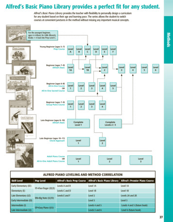
Automation and Drives - SCE1.PREFACE.In terms of its contents, Module C2 is part of the teaching unit entitled 'Programming Languages’.Fundamentals of STEP7Programming2 to 3 daysModule AAdditional Functions ofSTEP7Programming2 to 3 days Module BProgrammingLanguagesIndustrial FieldbusSystems2 to 3 days Module D2 to 3 days Module CFrequency Converterat SIMATIC S7Plant Simulation withSIMIT SCE1 to 2 days Module GProcessVisualization2 to3 days Module FIT Comminicationwith SIMATIC S72 to 3 days Module E2 to 3 days Module HLearning Objective:In module C2, the reader is introduced to the basic functions of the S7-SCL developmentenvironment. In addition, test functions are discussed for removing logical programming errors.Prerequisites:To successfully work through Module C2, the following knowledge is assumed: PrefaceKnowledge in handling WindowsFundamentals of PLC programming with STEP 7 (for example, Module A3 – 'Startup’PLC Programming with STEP 7)Basic knowledge of high level language programming, such as PascalNotesT I A Traning DocumentIssued: 02/2008InstallationDevelopment EnvironmentPage 5 of 34Sample ExerciseProjectProgramTestingModuleC2High Level Language Programming with S7-SCL
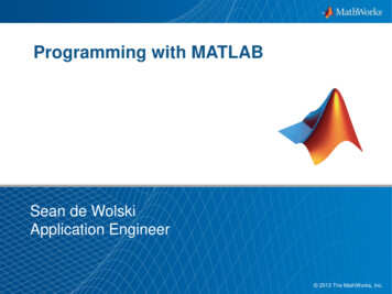
Automation and Drives - SCEHardware and software required123445PC, operating system Windows 2000 Professional starting with SP4/XP Professional startingwith SP1/Server 2003 with 600MHz and 512RAM, free hard disk storage 650 to 900 MB, MSInternet Explorer 6.0Software STEP7 V 5.4Software S7 SCL V5.xSoftware S7 PLCSIM V5.xMPI interface for the PC (for example, PC adapter USB)PLC SIMATIC S7-300 with at least one digital input and output module. The inputs have to betaken to a panelSample configuration:Power supply: PS 307 2ACPU: CPU 314Digital inputs: DI 16xDC24VDigital outputs: DO 16xDC24V/0.5 A2 STEP71 PC3 S7-SCL5 PC Adapter USB4 S7-PLCSIM6 SIMATIC S7-300PrefaceNotesT I A Traning DocumentIssued: 02/2008InstallationDevelopment EnvironmentPage 6 of 34Sample ExerciseProjectProgramTestingModuleC2High Level Language Programming with S7-SCL
Automation and Drives - SCE2.NOTES REGARDING THE PROGRAMMING LANGUAGE S7-SCLS7-SCL (Structured Control Language) is a higher level programming language that is based onPASCAL and makes structured programming possible. The language corresponds to the sequentialfunction chart SFC specified in the standard DIN EN-61131-3 (IEC 1131-3). In addition to the higherlevel language elements, S7-SCL also includes typical PLC elements such as inputs, outputs,timers, flags, block calls, etc. as language elements. It supports the STEP7 block concept andallows for non-standard programming of blocks, in addition to STL, LAD, and FBD. That means, S7SCL supplements and expands the programming software STEP7 and its programming languagesLAD, FBD, and STL.You do not have to generate each function yourself. You can resort to preassembled blocks such assystem functions and system function blocks that exist in the operating system of the CPU.Blocks that are programmed with S7-SCL can be mixed in with STL, LAD and FBD blocks. Thatmeans that a block that is programmed with S7-SCL can call another block that is programmed inSTL, LAD or FBD. Correspondingly, S7-SCL blocks can be called in STL, LAD, and FBD programs.When used in actual application cases, S7-SCL blocks can be recompiled into the STEP7programming language STL. Recompiling into the S7-SCL is not possible.During compilation, those blocks are generated from the previously edited program that are runnable-starting with CPU314- on all CPUs of the S7-300/400 automation system.The test functions of the S7-SCL allow for the search for logical programming errors in a faultlesscompilation. The errors are searched for in the source language.PrefaceNotesT I A Training DocumentIssued: 02/2008InstallationDevelopment EnvironmentPage 7 of 34Sample ExerciseProjectProgramTestingModuleC2High Level Language Programming withS7-SCL
Automation and Drives - SCE3.INSTALLING THE SOFTWARE S7-SCLS7-SCL is an option package for STEP7. This means, it is assumed that STEP7 is already installedon your computer. (Refer to Module A2 – Installation of STEP7 V5.x/Handling the Authorization).S7-SCL is delivered on a CD-ROM that includes a diskette. The diskette contains the license key(authorization) that has to be transferred to the PC. It makes utilizing the S7-SCL possible.The authorization can be retransferred to the diskette, to be used on another PC. Starting withSTEP7 Professional V5.3, this license can also be managed via a network. Regarding the topicInstallation and Transfer of Authorizations, please also refer to Module A2 – Installation of STEP7V5.x/Handling the Authorization.Now, to install S7-SCL, do the following:1. Place the S7-SCL CD in the CD-ROM drive.2. The setup program is started automatically. If not, start it by double clicking on the file ' setup.exe’.The setup program guides you through the entire installation of S7-SCL.3. To utilize S7-SCL, a license key (authorization) -that is, a utilization authorization- is requiredon your computer. You have to transfer it from the authorization diskette to the computer.This is done at the end of the installation. There, you will be asked in a dialog window by thesetup program whether you want to perform the authorization. If you select YES, you only haveto insert the authorization diskette and the authorization is transferred to your computer.PrefaceNotesT I A Training DocumentIssued: 02/2008InstallationDevelopment EnvironmentPage 8 of 34Sample ExerciseProjectProgramTestingModuleC2High Level Language Programming with S7-SCL
Automation and Drives - SCE4THE DEVELOPMENT ENVIRONMENT S7-SCLTo use S7-SCL, a development environment is provided that is adjusted to the specific features ofS7-SCL as well as of STEP7. This development environment consists of an Editor, a Compiler, and aDebugger.S7-SCL for S7-300/400EditorCompilerDebuggerEditorThe S7-SCL editor is a text editor with which any text can be edited. The central task that you willperform with it is generating and editing source files for STEP7 programs. In a source file, you canprogram one or several blocks. The syntax is not checked during the input.The editor offers the following:Editing a complete source file with one or several blocksEditing a compilation control file. With it, compiling several source files can be automatedUtilizing additional functions that make editing the source text possible; such as Search andReplace.Setting the editor according to your requirements; for example, through syntax-conformingcoloration of the different language elementsCompilerAfter you have generated your source files with the editor, they have to be compiled into S7 blocks.The compiler offers the following:Compiling an S7-SCL source file with several blocks in one compilation runCompiling several S7-SCL source files by using the compilation control file that contains thenames of the source filesSelectively compiling individual blocks from one sourceSetting the compiler according to your requirementsDisplaying all errors and warnings that occur during compilationLocalizing the faulty location in the source text, optionally with error description and informationfor error removalPrefaceNotesT I A Training DocumentIssued: 02/2008InstallationDevelopment EnvironmentPage 9 of 34Sample ExerciseProjectProgramTestingModuleC2High Level Language Programming withS7-SCL
Automation and Drives - SCEDebuggerThe S7-SCL debugger provides for checking a program during its run in the automation system, andlocating possible logical errors.S7-SCL offers two test modes for this:Step by step monitoringContinuous monitoringFor “step by step monitoring”, the logical program sequence is traced. You can execute the programalgorithm instruction by instruction, and observe in a result window how the edited variable contentschange.With “continuous monitoring“ you can test a group of instructions within a block of the source file.During the test run, the values of the variables and the parameters are displayed in a chronologicalsequence and -to the extent possible- updated cyclically.PrefaceNotesT I A Training DocumentIssued: 02/2008InstallationDevelopment EnvironmentPage 10 of 34Sample ExerciseProjectProgramTestingModuleC2High Level Language Programming withS7-SCL
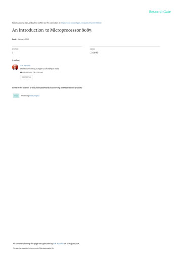
Automation and Drives - SCE5.SAMPLE EXERCISEIn this example, a natural number is to be squared. Before the result is calculated, a check is to bemade whether the value of the number is larger or equal to 181. If this is the case, the arithmeticfunction can be executed, and the result is returned. If not, the return value is to be “-1“.The number to be squared is to be entered in the integer format by means of an input word. Theoutput is made by means of an output word. The check and the calculation is to be programmed in afunction.Assignment List:IW 0 InputOW 0FC 1OutputSquareNumber to be squaredResultSquare functionProgram Structure:Organization BlockOB1- Calling the functionSquare with transferof input parametersFunction “Square“FC1- Output of Result- Checking andcalculating the result- Return of result orthe number "-1“Note: The value range of a number in integer format is between -32768 and 32767. The largestpossible natural number whose square is in this range is 181. To avoid exceeding the range, acheck is made prior to squaring.PrefaceNotesT I A Training DocumentIssued: 02/2008InstallationDevelopment EnvironmentPage 11 of 34Sample ExerciseProjectProgramTestingModuleC2High Level Language Programming withS7-SCL
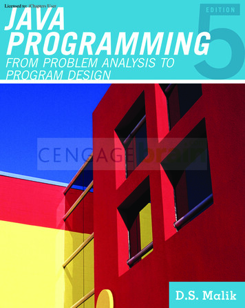
Automation and Drives - SCE6.SETTING UP A STEP7 PROJECTFiles are managed with the ‘SIMATIC Manager’, as in STEP7. Here, program blocks can be copied,for example, or called for further editing with other tools by clicking on them with the mouse. Theoperator input corresponds to the standards that are customary for WINDOWS95/98/2000/ME/NT4.0/XP. (For example, it is possible with one click of the right mouse key to get theselection menu for each component.)The hardware configuration of the PLC is mapped in the folders ’SIMATIC 300 Station’ and ’CPU’.Accordingly, such a project can always also be viewed specific to the hardware.As in STEP7, each project is set up in a structure that is permanently specified. The programs arestored in the following directories:SIMATIC 300 Stations:Here, the correspondinghardware configurationdata (Hardware/SC*1) andCPU data is stored .Project:This directory includes thehardware (for example,SIMATIC 300 stations) andthe subnets (such as MPI andPROFIBUS).Source/SO*1:Here, sources (such as SCLsources) are stored whichthrough compiling can beconverted into runnableprograms.Blocks/UP off*1:Here, the program blocks(OB, FB, FC, SFB, SFC,DB etc.) are stored.CPU:Here, the S7program and thenetworkedconnection partners(connections/CO*1)are entered.S7 Program:Here, the user programs(Blocks/UP off*1), the symboltables (Symbols/SY*1) andsources (Sources/SO*1) aremanaged.Symbols/SY*1:Here, the symbol lists forsymbolic addressing arestored.*1 Designations from STEP 7 Version 2.x.PrefaceNotesT I A Training DocumentIssued: 02/2008InstallationDevelopment EnvironmentPage 12 of 34Sample ExerciseProjectProgramTestingModuleC2High Level Language Programming withS7-SCL
Automation and Drives - SCETo generate a project regardless of the hardware configuration, it is possible to set up a project thatdoes not include these folders.It then has the following structure:Project:This directory includes thehardware (such as SIMATIC300 stations) and thesubnetworks (such as MPIand PROFIBUS).Sources/SO*1:Here, sources (such as SCLsources) are stored that canbe converted into runnableprograms throughcompilation.Blocks/UP off*1:Here, program blocks arestored (OB, FB, FC, SFB,SFC, DB etc.).Symbols/SY*1:Here, the symbol lists forsymbolic addressing arestored.S7 Program:Here, user programs(Blocks/UP off*1), symboltables (Symbols/SY*1) andsources (sources/SO*1) aremanaged.*1 Designations from STEP7 Version 2.xNote: This example is generated without hardware configuration. Therefore, the programs can beloaded to any configuration of SIMATIC S7-300, S7-400 or WinAC. Only the addresses of theinputs and outputs have to be adapted from case to case.PrefaceNotesT I A Training DocumentIssued: 02/2008InstallationDevelopment EnvironmentPage 13 of 34Sample ExerciseProjectProgramTestingModuleC2High Level Language Programming withS7-SCL
Automation and Drives - SCEThe user has to perform the following steps to generate a project where the solution program can bewritten.1.The central tool in STEP7 is the SIMATIC Manager. It is called here with a double click. ( SIMATIC Manager)2. S7-SCL programs are managed in STEP7 projects. Such a project will now be set up ( File New)PrefaceNotesT I A Training DocumentIssued: 02/2008InstallationDevelopment EnvironmentPage 14 of 34Sample ExerciseProjectProgramTestingModuleC2High Level Language Programming with S7-SCL
Automation and Drives - SCE3.The project is now assigned the ’Name’ ’scl startup’. ( scl startup OK)4. In the project ’scl startup’, a new ’S7 Program’ is inserted. ( scl startup Insert Program S7 Program)PrefaceNotesT I A Training DocumentIssued: 02/2008InstallationDevelopment EnvironmentPage 15 of 34Sample ExerciseProjectProgramTestingModuleC2High Level Language Programming with S7-SCL
Automation and Drives - SCE7.WRITING THE STEP 7 PROGRAM IN S7-SCL1.To insert an S7-SCL source, the folder ’Sources’ has to be highlighted. ( Sources)2.An ’SCL Source’ is inserted. ( Insert S7 Software SCL Source)PrefaceNotesT I A Training DocumentIssued: 02/2008InstallationDevelopment EnvironmentPage 16 of 34Sample ExerciseProjectProgramTestingModuleC2High Level Language Programming with S7-SCL
Automation and Drives - SCE3.In the SIMATIC Manager, an SCL source is now available for programming.Note: You can change the name of the SCL source. This is advisable for better readability of theprogram in the case of a complex control task with several sources. To this end, click on the sourcewith the right mouse key, and select ’Rename’ from the menu.4. Now, the SCL editor is to be started. To this end, the source in the SIMATIC Manager isopened with a double click. ( SCL Source)PrefaceNotesT I A Training DocumentIssued: 02/2008InstallationDevelopment EnvironmentPage 17 of 34Sample ExerciseProjectProgramTestingModuleC2High Level Language Programming with S7-SCL
Automation and Drives - SCE5.The programming interface for programming in SCL looks like this:SavesourceCompile source andgenerate blocksLoad blocksto CPUIn this text editor, thecontrol job can begenerated by means ofthe source code in S7SCLHere, errors and warningsare displayed that possiblyoccurred duringconmpilationPrefaceNotesT I A Training DocumentIssued: 02/2008InstallationDevelopment EnvironmentPage 18 of 34Here, the function’Monitoring’ can beactivatedSample ExerciseProjectProgramTestingModuleC2High Level Language Programming with S7-SCL
Automation and Drives - SCE6.First, the symbol table is to be created. ( Options Symbol Table)7.Enter operands in symbol table ( Symbol Address Data Type Comment) andsave symbol lists ( PrefaceNotesT I A Training DocumentIssued: 02/2008Installation).Development EnvironmentPage 19 of 34Sample ExerciseProjectProgramTestingModuleC2High Level Language Programming with S7-SCL
Automation and Drives - SCE8. Now, the program can be entered in the editor’s text field by using the symbolic names. For theexample in S7-SCL, this could look like this:Square :// Squares a number in the integer format if the value is 181// The return is the result of the square or -1 if there is an error// The return value is in the integer format//Define input variableNbr//Define temporary variableResult :Nbr)Result :(Nbr)//Check whether the value of number 181//If yes, result is square of number//If no, result is -1Result :Square :(Result)//Type conversion and returnOrganization block with call of a function block//reservedOutput: square (input);//Calling the function SquareNote: It is possible to program all blocks of a source file. It should be noted in this case that theblock that is called is always programmed before the block that is calling.PrefaceNotesT I A Training DocumentIssued: 02/2008InstallationDevelopment EnvironmentPage 20 of 34Sample ExerciseProjectProgramTestingModuleC2High Level Language Programming with S7-SCL
Automation and Drives - SCE9. Before the source is stored, the compiler ’Settings’ have to be adjusted. ( Options Settings)10. Under the tab ’Compiler’, the following settings have to be made. ( Compiler OK)PrefaceNotesT I A Training DocumentIssued: 02/2008InstallationDevelopment EnvironmentPage 21 of 34Sample ExerciseProjectProgramTestingModuleC2High Level Language Programming with S7-SCL
Automation and Drives - SCE11. Now, the program can be saved, compiledand checked for syntax errors. After allerrors are remedied, the blocks can be loaded to the CPU.( )SquareSquares a number in the integer format if the value is 181Return value is the result of the square or -1 if there is an errorThe return value is in the interger formatNumber//Define input variableResultDefine temporary variableCompiling: scl startup\S7 program(1)\Sources\SCL source(1)SCL source: SCL source(1)Block: SquareBlock: OB1Result: 0 errors, 0 warning(s)ErrorNote: If several blocks are programmed in one source, it is possible to compile the blocksindividually, (PrefaceNotesT I A Training DocumentIssued: 02/2008) and to load them to the CPU individually. (InstallationDevelopment EnvironmentPage 22 of 34Sample Exercise)ProjectProgramTestingModuleC2High Level Language Programming with S7-SCL
Automation and Drives - SCE8.TESTING THE STEP 7 PROGRAM IN THE CPUThe S7-SCL test functions allow for checking a program during its run in the CPU and find possibleerrors. Syntax errors are displayed during compilation. Timeouts during program execution are alsoindicated by system alarms. Logical programming errors can be determined with the test functions.8.1Operating ModesScanning test information usually extends the cycle time. In order to be able to influence this timeextension, SCL offers two different operating modes.Test ModeIn the operating mode ’Test Mode’, the monitoring range is limited only by the performancecapability of the connected CPU. All test functions can be used without restriction. Longerextensions of the CPU cycle time can occur since, for example, the status of instructions inprogrammed loops is ascertained for each run.Process ModeIn the operating mode ’Process Mode’, the SCL debugger limits the maximum monitoring range in away that the cycle duration during the test process does not exceed or only insignificantly exceedsthe real run time.1. The desired operating mode can be selected in the menu ’Test’. The mode that is actually set ismarked with a dot ( Test Mode Test Mode)PrefaceNotesT I A Training DocumentIssued: 02/2008InstallationDevelopment EnvironmentPage 23 of 34Sample ExerciseProjectProgramTestingModuleC2High Level Language Programming withS7-SCL
Automation and Drives - SCE8.2Monitoring the STEP7 ProgramThe development environment S7-SCL makes two different test functions available.Continuous monitoringWith this function, you can read out names and current values of variables in the SCL source. Duringthe test run, the values of the variables and parameters of this area are displayed in a chronologicalsequence, and updated cyclically.Step by step monitoring (only S7-400 CPUs)With this function, you can set stop points, and then perform a test run in single steps. It is possibleto execute the program algorithm instruction by instruction, for example, and monitor how the valuesof the processed variables change.8.2.1Continuous MonitoringWhen continuously monitoring a program, you can test a group of instructions. This group ofinstructions is also called Monitoring Area. If the monitoring area is located in a program part that ispassed in each cycle, the values of the variables can, as a rule, not be recorded from successivecycles.Values that changed during the current run, and values that did not change can be differentiated bycolor.The scope of instructions to be tested is limited by the performance capacity of the connected CPU.Since the SCL instructions of the source code are mapped to a varying number of instructions in themachine code, the length of the monitoring area is variable. The SCL debugger ascertains andmarks the length if you select the first instruction of the desired monitoring area.PrefaceNotesT I A Training DocumentIssued: 02/2008InstallationDevelopment EnvironmentPage 24 of 34Sample ExerciseProjectProgramTestingModuleC2High Level Language Programming withS7-SCL
Automation and Drives - SCE1. By clicking on the eye glass symbol, the program can be monitored continuously. In thepartial window on the left, the area that is monitored is shown with a gray bar. In the right window,the values are displayed. ( .Result(ResulSquareResult3. The test function has to be closed in the menu ’Test’. ( Test Close Test)Note: If you deactivate the function ’Monitoring’ with the eye glass symbol, the split window issaved. The program continues to be open ONLINE and can not be edited. However, you can set,clear, or edit stop points, and monitor the program sequence step by step.PrefaceNotesT I A Training DocumentIssued: 02/2008InstallationDevelopment EnvironmentPage 25 of 34Sample ExerciseProjectProgramTestingModuleC2High Level Language Programming withS7-SCL
Automation and Drives - SCE8.2.2Step by Step MonitoringWhen testing with stop points, the test is run in individual steps. The program algorithm can beexecuted instruction by instruction, and you can monitor how the values of the edited variableschange. The number of stop points depends on the CPU that is connected.After the stop points are set, you can have the program executed initially up to a stop point. Whenthe CPU reaches this instruction, it enters the STOP mode, and from there, you can start with stepby step monitoring.Allows for activating/deactivating/clearing stop points that were set, and for specifying thatcertain stop points are active only in a defined call environment.Sets or clears stop points at the current position of the mouse pointer. This menu commandis active only if you are not performing the function "Monitoring" at the moment; that is, if themenu command Monitor is not marked with a check mark.Clears all stop points of the current S7 program. This menu command is active only if youare not performing the function "Monitoring" at the moment; that is, if the menu commandMonitor is not marked with a check mark.Turns on the test mode "Testing with stop points". This menu command is active only if youare not performing the function "Monitoring" at the moment; that is, if the menu commandMonitor is not marked with a check mark.Executes the program up to the next stop point. When this stop point is reached, the CPUenters the STOP mode.Executes the SCL instruction at the current position. After the instruction is executed, theCPU enters the STOP mode, the insertion point is moved to the next instruction, and thecontents of the variables in the instruction that was edited last are displayed.The program is executed up to the current position of the insertion point. The CPU entersthe STOP mode.If the block that is called is a block generated by SCL, the menu command Execute Callcauses the block that is called to be opened, and the program stops at the first instruction ofthe block. You now can monitor the block step by step with the single step functions. Whenthe end of the block is reached, the program jumps back to the block that is calling, andstops in the line following the block call. If the block that is called is a block that is notgenerated by SCL, the call is skipped and the program line that follows is marked.PrefaceNotesT I A Training DocumentIssued: 02/2008InstallationDevelopment EnvironmentPage 26 of 34Sample ExerciseProjectProgramTestingModuleC2High Level Language Programming withS7-SCL
Automation and Drives - SCESample Exercise: Expanding and TestingTo better illustrate the different possibilities in the test mode, the sample exercise is supplemented.Three different integers are to be squared and read out. To this end, the function Square in OB1 iscalled three times in succession. At each call, the input parameters are to be adapted to therespective input word. The output of the different results is to be placed on different output words.1. To this end, supplement the symbol table as follows:IW 0 Input 1First number to be squaredIW 2 Input 2Second number to be squaredIW 4 Input 3Third number to be squaredOW 0Output 1Result 1OW 2Output 2Result 2OW 4Output 3Result 3FC 1SquareSquare function2. The symbol bar for the stop point commands can be inserted in the menu View 'Stop Point Bar’.This is confirmed with a check mark at the menu option ( View Stop Point Bar).PrefaceNotesT I A Training DocumentIssued: 02/2008InstallationDevelopment EnvironmentPage 27 of 34Sample ExerciseProjectProgramTestingModuleC2High Level Language Programming withS7-SCL
Automation and Drives - SCE3. The additional calls of the function Square are inserted in the SCL source. Then, the program hasto be saved, compiledand checked for syntax errors. After all errors are removed, theblocks can be loaded to the CPU.( ).4. Place the mark in the line with the first call of function FC1 and insert a stop point by clicking on.( the button)Note: It is possible to insert several stop points. To this end, mark the desired line and insert anadditional stop pointbuttonPrefaceNotesT I A Training DocumentIssued: 02/2008. To clear a stop point that you already set, mark it and then use the same.InstallationDevelopment EnvironmentPage 28 of 34Sample ExerciseProjectProgramTestingModuleC2High Level Language Programming withS7-SCL
Automation and Drives - SCE5. Now, step by step monitoring is started by activating the stop points that were setto edit the first instruction and have it displayed in the right partial window. ( 6. You can have the next instruction edited by another click on.( . Click on ))Note: For step by step monitoring, only the values of the instruction that is currently processed isdisplayed. Although block calls are executed with the command ’To next instruction’not displayed step by step.PrefaceNotesT I A Training DocumentIssued: 02/2008InstallationDevelopment EnvironmentPage 29 of 34Sample ExerciseProjectProgram, they areTestingModuleC2High Level Language Programming withS7-SCL
Automation and Drives - SCE7. A called block can be monitored step by step with the command ’Execute Call’instruction is displayed with the function ’To next instruction’.( . The first).8. Each additional instruction is processed and displayed with the same function.( Note: If the end of the block is reached and if the command ’To next instruction’again, the instruction is edited after the block call of the calling block.PrefaceNotesT I A Training DocumentIssued: 02/2008InstallationDevelopment EnvironmentPage 30 of 34Sample ExerciseProjectProgram)is executedTesting
STL, LAD or FBD. Correspondingly, S7-SCL blocks can be called in STL, LAD, and FBD programs. When used in actual application cases, S7-SCL blocks can be recompiled into the STEP7 programming language STL. Recompiling into the S7-SCL is not possible. During compilation, those blocks are generated from the previously edited program that are runnable