Transcription
Fitting Simulation& KinematicsNATIONAL INSTITUTE FOR AVIATION RESEARCHWichita State UniversityRevision 5.14Copyright 2005. All rights reserved.www.cadcamlab.org
None of this material may be reproduced, used or disclosed, in part or in whole, without the expressed written permission of:National Institute for Aviation ResearchWichita State UniversityWichita, KSCopyright 2005. All rights reserved.www.cadcamlab.org
CATIA KinematicsCATIA V5R14TABLE OF CONTENTSIntroduction . . . . . . . . . . . . . . . . . . . . . . . . . . . . . . . . . . . . . . . . . . . . . . . . . . . . . . . . . . . . . . 1Fitting Simulation . . . . . . . . . . . . . . . . . . . . . . . . . . . . . . . . . . . . . . . . . . . . . . . . . . . 2Pull Down Menus . . . . . . . . . . . . . . . . . . . . . . . . . . . . . . . . . . . . . . . . . . . . . . . . . . . 3Insert . . . . . . . . . . . . . . . . . . . . . . . . . . . . . . . . . . . . . . . . . . . . . . . . . . . . . . . . 3Tools . . . . . . . . . . . . . . . . . . . . . . . . . . . . . . . . . . . . . . . . . . . . . . . . . . . . . . . 4Analyze . . . . . . . . . . . . . . . . . . . . . . . . . . . . . . . . . . . . . . . . . . . . . . . . . . . . . 5Window . . . . . . . . . . . . . . . . . . . . . . . . . . . . . . . . . . . . . . . . . . . . . . . . . . . . . 5Fitting Simulation Workbench . . . . . . . . . . . . . . . . . . . . . . . . . . . . . . . . . . . . . . . . . . 6Manipulation . . . . . . . . . . . . . . . . . . . . . . . . . . . . . . . . . . . . . . . . . . . . . . . . . 7Recorder . . . . . . . . . . . . . . . . . . . . . . . . . . . . . . . . . . . . . . . . . . . . . . . . . . . . . 8Player . . . . . . . . . . . . . . . . . . . . . . . . . . . . . . . . . . . . . . . . . . . . . . . . . . . . . . . 8Bottom Toolbar . . . . . . . . . . . . . . . . . . . . . . . . . . . . . . . . . . . . . . . . . . . . . . . . . . . . . 9Viewing . . . . . . . . . . . . . . . . . . . . . . . . . . . . . . . . . . . . . . . . . . . . . . . . . . . . . 9Fitting Simulation . . . . . . . . . . . . . . . . . . . . . . . . . . . . . . . . . . . . . . . . . . . . . . . . . . . . . . . . 11Creating Tracks . . . . . . . . . . . . . . . . . . . . . . . . . . . . . . . . . . . . . . . . . . . . . . . . . . . . 11Compass . . . . . . . . . . . . . . . . . . . . . . . . . . . . . . . . . . . . . . . . . . . . . . . . . . . . . . . . . . 12Color Action . . . . . . . . . . . . . . . . . . . . . . . . . . . . . . . . . . . . . . . . . . . . . . . . . . . . . . . 21Visibility Action . . . . . . . . . . . . . . . . . . . . . . . . . . . . . . . . . . . . . . . . . . . . . . . . . . . . 22Sequences . . . . . . . . . . . . . . . . . . . . . . . . . . . . . . . . . . . . . . . . . . . . . . . . . . . . . . . . . 23Shuttles . . . . . . . . . . . . . . . . . . . . . . . . . . . . . . . . . . . . . . . . . . . . . . . . . . . . . 28Creating a Sequence from Explode . . . . . . . . . . . . . . . . . . . . . . . . . . . . . . . 39Modifying Tracks . . . . . . . . . . . . . . . . . . . . . . . . . . . . . . . . . . . . . . . . . . . . . . . . . . . 41Reordering Shots . . . . . . . . . . . . . . . . . . . . . . . . . . . . . . . . . . . . . . . . . . . . . 41Reusing Shots . . . . . . . . . . . . . . . . . . . . . . . . . . . . . . . . . . . . . . . . . . . . . . . . 43Shot Time . . . . . . . . . . . . . . . . . . . . . . . . . . . . . . . . . . . . . . . . . . . . . . . . . . . 45Adding, Deleting and Modifying Shots . . . . . . . . . . . . . . . . . . . . . . . . . . . . 47Advanced Tracks . . . . . . . . . . . . . . . . . . . . . . . . . . . . . . . . . . . . . . . . . . . . . . . . . . . 49Mirroring Tracks . . . . . . . . . . . . . . . . . . . . . . . . . . . . . . . . . . . . . . . . . . . . . 50Reversing Tracks . . . . . . . . . . . . . . . . . . . . . . . . . . . . . . . . . . . . . . . . . . . . . 55Joining Tracks . . . . . . . . . . . . . . . . . . . . . . . . . . . . . . . . . . . . . . . . . . . . . . . 60Clash Detection . . . . . . . . . . . . . . . . . . . . . . . . . . . . . . . . . . . . . . . . . . . . . . . . . . . . 63Path Finder . . . . . . . . . . . . . . . . . . . . . . . . . . . . . . . . . . . . . . . . . . . . . . . . . . . . . . . . 67Smooth . . . . . . . . . . . . . . . . . . . . . . . . . . . . . . . . . . . . . . . . . . . . . . . . . . . . . . . . . . . 71Angle Validation . . . . . . . . . . . . . . . . . . . . . . . . . . . . . . . . . . . . . . . . . . . . . . . . . . . 74Advanced Sequences . . . . . . . . . . . . . . . . . . . . . . . . . . . . . . . . . . . . . . . . . . . . . . . . 77Advanced Shuttles . . . . . . . . . . . . . . . . . . . . . . . . . . . . . . . . . . . . . . . . . . . . 77Gantt Chart . . . . . . . . . . . . . . . . . . . . . . . . . . . . . . . . . . . . . . . . . . . . . . . . . . 85Generating a Replay . . . . . . . . . . . . . . . . . . . . . . . . . . . . . . . . . . . . . . . . . . . 88Generating a Video . . . . . . . . . . . . . . . . . . . . . . . . . . . . . . . . . . . . . . . . . . . 89Clash Analysis . . . . . . . . . . . . . . . . . . . . . . . . . . . . . . . . . . . . . . . . . . . . . . . . . . . . . 90Distance Analysis . . . . . . . . . . . . . . . . . . . . . . . . . . . . . . . . . . . . . . . . . . . . . . . . . . . 97Analysis with Sequences . . . . . . . . . . . . . . . . . . . . . . . . . . . . . . . . . . . . . . . . . . . . 102Swept Volumes . . . . . . . . . . . . . . . . . . . . . . . . . . . . . . . . . . . . . . . . . . . . . . . . . . . 106Experiments . . . . . . . . . . . . . . . . . . . . . . . . . . . . . . . . . . . . . . . . . . . . . . . . . . . . . . 109Other Tracks . . . . . . . . . . . . . . . . . . . . . . . . . . . . . . . . . . . . . . . . . . . . . . . . . . . . . . 115 Wichita State UniversityTable of Contents, Page i
CATIA KinematicsCATIA V5R14Introduction . . . . . . . . . . . . . . . . . . . . . . . . . . . . . . . . . . . . . . . . . . . . . . . . . . . . . . . . . . . . 117Kinematics . . . . . . . . . . . . . . . . . . . . . . . . . . . . . . . . . . . . . . . . . . . . . . . . . . . . . . . 118Pull Down Menus . . . . . . . . . . . . . . . . . . . . . . . . . . . . . . . . . . . . . . . . . . . . . . . . . 119Insert . . . . . . . . . . . . . . . . . . . . . . . . . . . . . . . . . . . . . . . . . . . . . . . . . . . . . . 119Tools . . . . . . . . . . . . . . . . . . . . . . . . . . . . . . . . . . . . . . . . . . . . . . . . . . . . . 121Analyze . . . . . . . . . . . . . . . . . . . . . . . . . . . . . . . . . . . . . . . . . . . . . . . . . . . 122Window . . . . . . . . . . . . . . . . . . . . . . . . . . . . . . . . . . . . . . . . . . . . . . . . . . . 122Kinematics Workbench . . . . . . . . . . . . . . . . . . . . . . . . . . . . . . . . . . . . . . . . . . . . . 123Player . . . . . . . . . . . . . . . . . . . . . . . . . . . . . . . . . . . . . . . . . . . . . . . . . . . . . 124Bottom Toolbar . . . . . . . . . . . . . . . . . . . . . . . . . . . . . . . . . . . . . . . . . . . . . . . . . . . 125Viewing . . . . . . . . . . . . . . . . . . . . . . . . . . . . . . . . . . . . . . . . . . . . . . . . . . . 125Kinematics . . . . . . . . . . . . . . . . . . . . . . . . . . . . . . . . . . . . . . . . . . . . . . . . . . . . . . . . . . . . . 127Joints . . . . . . . . . . . . . . . . . . . . . . . . . . . . . . . . . . . . . . . . . . . . . . . . . . . . . . . . . . . 127Revolute - Null Offset . . . . . . . . . . . . . . . . . . . . . . . . . . . . . . . . . . . . . . . . 128Revolute - Centered . . . . . . . . . . . . . . . . . . . . . . . . . . . . . . . . . . . . . . . . . . 134Prismatic . . . . . . . . . . . . . . . . . . . . . . . . . . . . . . . . . . . . . . . . . . . . . . . . . . 137Cylindrical - Angle and Length . . . . . . . . . . . . . . . . . . . . . . . . . . . . . . . . . 140Cylindrical - Length . . . . . . . . . . . . . . . . . . . . . . . . . . . . . . . . . . . . . . . . . . 143Cylindrical - Angle . . . . . . . . . . . . . . . . . . . . . . . . . . . . . . . . . . . . . . . . . . . 145Screw . . . . . . . . . . . . . . . . . . . . . . . . . . . . . . . . . . . . . . . . . . . . . . . . . . . . . 147Spherical . . . . . . . . . . . . . . . . . . . . . . . . . . . . . . . . . . . . . . . . . . . . . . . . . . 150Planar . . . . . . . . . . . . . . . . . . . . . . . . . . . . . . . . . . . . . . . . . . . . . . . . . . . . . 152Rigid . . . . . . . . . . . . . . . . . . . . . . . . . . . . . . . . . . . . . . . . . . . . . . . . . . . . . . 154Point Curve . . . . . . . . . . . . . . . . . . . . . . . . . . . . . . . . . . . . . . . . . . . . . . . . 156Slide Curve . . . . . . . . . . . . . . . . . . . . . . . . . . . . . . . . . . . . . . . . . . . . . . . . . 158Roll Curve . . . . . . . . . . . . . . . . . . . . . . . . . . . . . . . . . . . . . . . . . . . . . . . . . 160Point Surface . . . . . . . . . . . . . . . . . . . . . . . . . . . . . . . . . . . . . . . . . . . . . . . 163Universal . . . . . . . . . . . . . . . . . . . . . . . . . . . . . . . . . . . . . . . . . . . . . . . . . . 166Constant Velocity . . . . . . . . . . . . . . . . . . . . . . . . . . . . . . . . . . . . . . . . . . . . 171Gear . . . . . . . . . . . . . . . . . . . . . . . . . . . . . . . . . . . . . . . . . . . . . . . . . . . . . . 174Rack . . . . . . . . . . . . . . . . . . . . . . . . . . . . . . . . . . . . . . . . . . . . . . . . . . . . . . 178Cable . . . . . . . . . . . . . . . . . . . . . . . . . . . . . . . . . . . . . . . . . . . . . . . . . . . . . 181Joints using Axis Systems . . . . . . . . . . . . . . . . . . . . . . . . . . . . . . . . . . . . . 183Assembly Constraints . . . . . . . . . . . . . . . . . . . . . . . . . . . . . . . . . . . . . . . . . . . . . . 187Auto Create . . . . . . . . . . . . . . . . . . . . . . . . . . . . . . . . . . . . . . . . . . . . . . . . 187Advanced . . . . . . . . . . . . . . . . . . . . . . . . . . . . . . . . . . . . . . . . . . . . . . . . . . 189Simulations . . . . . . . . . . . . . . . . . . . . . . . . . . . . . . . . . . . . . . . . . . . . . . . . . . . . . . 195Simulation . . . . . . . . . . . . . . . . . . . . . . . . . . . . . . . . . . . . . . . . . . . . . . . . . 195Compiling the simulation . . . . . . . . . . . . . . . . . . . . . . . . . . . . . . . . . . . . . . 198Replay . . . . . . . . . . . . . . . . . . . . . . . . . . . . . . . . . . . . . . . . . . . . . . . . . . . . 199Simulation player . . . . . . . . . . . . . . . . . . . . . . . . . . . . . . . . . . . . . . . . . . . . 200Sequences . . . . . . . . . . . . . . . . . . . . . . . . . . . . . . . . . . . . . . . . . . . . . . . . . . 202Generate Replay . . . . . . . . . . . . . . . . . . . . . . . . . . . . . . . . . . . . . . . . . . . . . 205Generate Video . . . . . . . . . . . . . . . . . . . . . . . . . . . . . . . . . . . . . . . . . . . . . 206Knowledgeware . . . . . . . . . . . . . . . . . . . . . . . . . . . . . . . . . . . . . . . . . . . . . . . . . . . 208Laws . . . . . . . . . . . . . . . . . . . . . . . . . . . . . . . . . . . . . . . . . . . . . . . . . . . . . . 208Rules . . . . . . . . . . . . . . . . . . . . . . . . . . . . . . . . . . . . . . . . . . . . . . . . . . . . . 212Table of Contents, Page ii Wichita State University
CATIA KinematicsCATIA V5R14Path Generation . . . . . . . . . . . . . . . . . . . . . . . . . . . . . . . . . . . . . . . . . . . . . . . . . . . 216Traces . . . . . . . . . . . . . . . . . . . . . . . . . . . . . . . . . . . . . . . . . . . . . . . . . . . . . 216Swept Volumes . . . . . . . . . . . . . . . . . . . . . . . . . . . . . . . . . . . . . . . . . . . . . 219Sensors . . . . . . . . . . . . . . . . . . . . . . . . . . . . . . . . . . . . . . . . . . . . . . . . . . . . . . . . . . 225Speed and Acceleration . . . . . . . . . . . . . . . . . . . . . . . . . . . . . . . . . . . . . . . 231Clash and Distance . . . . . . . . . . . . . . . . . . . . . . . . . . . . . . . . . . . . . . . . . . . 235Joint Limits . . . . . . . . . . . . . . . . . . . . . . . . . . . . . . . . . . . . . . . . . . . . . . . . 241Mechanism Dressup . . . . . . . . . . . . . . . . . . . . . . . . . . . . . . . . . . . . . . . . . . . . . . . . 243Mechanism Analysis . . . . . . . . . . . . . . . . . . . . . . . . . . . . . . . . . . . . . . . . . . . . . . . 247Tracks and Simulations . . . . . . . . . . . . . . . . . . . . . . . . . . . . . . . . . . . . . . . . . . . . . 249Problems . . . . . . . . . . . . . . . . . . . . . . . . . . . . . . . . . . . . . . . . . . . . . . . . . . . . . . . . . . . . . . 251Problem #1 . . . . . . . . . . . . . . . . . . . . . . . . . . . . . . . . . . . . . . . . . . . . . . . . . . . . . . . 251Problem #2 . . . . . . . . . . . . . . . . . . . . . . . . . . . . . . . . . . . . . . . . . . . . . . . . . . . . . . . 252Problem #3 . . . . . . . . . . . . . . . . . . . . . . . . . . . . . . . . . . . . . . . . . . . . . . . . . . . . . . . 253Problem #4 . . . . . . . . . . . . . . . . . . . . . . . . . . . . . . . . . . . . . . . . . . . . . . . . . . . . . . . 254Problem #5 . . . . . . . . . . . . . . . . . . . . . . . . . . . . . . . . . . . . . . . . . . . . . . . . . . . . . . . 255Problem #6 . . . . . . . . . . . . . . . . . . . . . . . . . . . . . . . . . . . . . . . . . . . . . . . . . . . . . . . 256Appendix A . . . . . . . . . . . . . . . . . . . . . . . . . . . . . . . . . . . . . . . . . . . . . . . . . . . . . . . . . . . . 259Digital Mockup - DMU Fitting - DMU Fitting . . . . . . . . . . . . . . . . . . . . . . . . . . . 259Digital Mockup - DMU Fitting - DMU Manipulation . . . . . . . . . . . . . . . . . . . . . . 260 Wichita State UniversityTable of Contents, Page iii
CATIA KinematicsTable of Contents, Page ivCATIA V5R14 Wichita State University
CATIA Fitting SimulationCATIA V5R14Advanced TracksSometimes creating each individual track is unnecessary. There are a number of operationsthat can be applied to tracks that will hasten the simulation process.Open the Advanced Tracks document located in the Advanced Tracks directory. Wichita State UniversityFitting Simulation - Advanced Tracks, Page 49
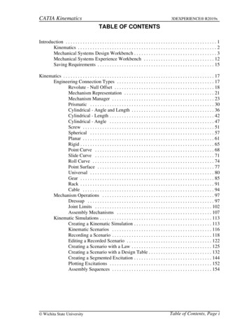
CATIA Fitting SimulationCATIA V5R14Mirroring TracksTo mirror a track, all you have to do is place the compass on the mirror plane, with the baseof the compass (the XY plane) on the mirror plane. The ZX primary plane for the propellerwill work just fine.Unhide the ZX plane in the Propeller. Just expand out the tree for the propeller, and thenunhide the ZX plane.Select the track icon. Select the right landing pad as shown above. The right landingpad will be labeled 1x8 Thin Block.1. You will probably want to modify the parameters forcompass manipulation to have a 0 inch Translation increment for Along W. This will allowfor smaller movements in the W direction.Create the following track. This track will be created with the Interpolater set to Linear.Do not worry about moving the pad front to back, only along the YZ plane.Fitting Simulation - Advanced Tracks, Page 50 Wichita State University
CATIA Fitting SimulationCATIA V5R14Change the Interpolater to Composite spline. If you remember, before when you changedthe Interpolater to a composite spline, the only thing that seemed to happen is the objectslowed down as it went around a corner. Notice what happens this time.What is really happening with a composite spline is, the points that are close together areconverted to a spline, where as the longer stretches are left as lines. This makes for morefluid and smooth motions as the track progresses.Select OK when done. That has one track done. Now, the other pad needs to have theexact same track applied, but in a mirrored fashion.Drag the compass and place it on the Propeller plane. This may be a bit of a trick. Makesure that you are zoomed in on the plane. To drag the compass, select the large red dot onthe center of the base of the compass, and then drag it to one of the edges of the plane. Youwill have to drag it to the edge before it will stick to the plane. The result should looksomething like this. Wichita State UniversityFitting Simulation - Advanced Tracks, Page 51
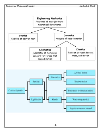
CATIA Fitting SimulationCATIA V5R14Now it is time to mirror the track so that it can be used for the other helicopter pad.With the third mouse button, select on the track just created, and then select the trackobject. Notice there are a series of operations that can be applied to the track.DefinitionTakes you back to the definition of the trackReverse timeReverses the track and make it run backwardsJoinJoins two different tracks togetherSplitSpits a track into different segmentsMirror trackMirrors a track around the base plane of the compassUpdateUpdates the track if changes have occurredBreak linkErases the history of a track, making it a stand-alone trackSelect Mirror track.This mirrors the track around the base plane of the compass. Itis mandatory that the compass be in a proper location before trying to mirror the track.Now that you have the track in place, you need to associate it to the other landing pad.Fitting Simulation - Advanced Tracks, Page 52 Wichita State University
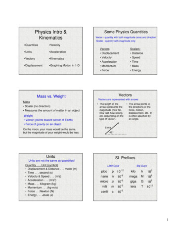
CATIA Fitting SimulationCATIA V5R14Notice the new track. The new track has a long line of sub branches. Take a quick look atthe various sub branches.The first sub branch is the Mirror track branch. It shows what operation has beenperformed. The next branch down is the Track.1 1x8 Thin Block.1 branch, the track thatwas mirrored. The Parameters branch is the parameters of the mirror. This defines whatthe track was mirrored around, and other various information about the mirroring of thetrack.Double select the new track. This should be Track.2 1x8 Thin Block.1, but just know it isthe second track. This will take you back to the definition of the first track.Select the Object field. This will bring up the Track Positioning window. Last time youtold it to not keep the positioning of the track. Since the mirrored track is in the correctplace as it is, then you will want to keep the positioning.Select Keep Positioning from the Track Positioning window. Now the track will notmove, but will still work with the second block.Select the 1x8 Thin Block (1x8 Thin Block.2). You may have to select it from the tree.The original block will lay on top of the second one, making it difficult to select graphically.Select OK when you are done, then select the reset position icon.ready to replay the two of them to see how they look.Select the player icon and then the first track.Now you areThe Player toolbar appears.Select the skip to begin icon and then the play forward icon. The block moves downand to the right.Select the second track and play it. The block moves down and to the left.Close the Player toolbar. You can close the window by selecting the X in the upper rightcorner or you can select the player icon again. You are going to make a modification to thefirst track. Wichita State UniversityFitting Simulation - Advanced Tracks, Page 53
CATIA Fitting SimulationCATIA V5R14Double select on the first track. You have to select the player icon to turn it off.Otherwise, the player will change back to the first track, waiting for you to replay it.Move the landing pad straight forward, and inward as shown below. Select OK whendone. Do not worry about the Z movements, Just assume everything is along the XY plane.Notice the other track did not change as you thought it might. You are going to remove theold track and then mirror the track again.Select the player icon and select Track.2 1x8 Thin Block.2.appears.The Player toolbarSelect the skip to begin icon and close the Player toolbar. This will locate that block atthe original position.Delete Track.2. You are going to create a new track by mirroring the modified one.Drag the compass and position it on the plane again. You must define a mirror planewith the compass.Press the third mouse button while on Track.1 1x8 Thin Block.1, select the object nameand select Mirror track.The modified track is mirrored. You will need to change theobject it is associated with.Double select Track.2 1x8 Thin Block.1, select in the Object box, turn on Keeppositioning and select the 1x8 Thin Block (1x8 Thin Block.2). You will probably need toselect it from the tree.Select OK, then select the reset position icon.Now you should be able to replayboth of the tracks. Now that you have the two landing pads dis-assembling, it is time toreverse the tracks to put it back together.Fitting Simulation - Advanced Tracks, Page 54 Wichita State University
CATIA Fitting SimulationCATIA V5R14Reversing TracksWith the third mouse button, select on the first track, and then the track object. Thisis going to bring up the contextual menu for the track.Select Reverse time.This is going to reverse the time for the track. Notice a Reversetime branch is added to the tree.Select the player icon and the first track. Select the skip to begin icon and then playthe track. Notice the landing pad now starts at the end of the track, and finishes where itoriginally was. Even though the second track is a mirror of the first track, the operationsperformed on the tracks do not mirror. This means that if you replay the second track, itwill not be in reversed time.Close the Player and reverse the time for the second track. This is just the same processas before, select on the track with the third mouse button, select the track object, and thenselect Reverse time. This will add another branch to the track.Now the second track, Track.2 1x8 Thin Block.2, has two operations performed on it, amirror and a reverse time. You can have as many operations performed on a track as youwant. There is another method to run a track in reverse that does not utilize a reverse timeoperation. This will be looked at next. Wichita State UniversityFitting Simulation - Advanced Tracks, Page 55
CATIA Fitting SimulationCATIA V5R14Create a shuttle that consists of the Propeller and both blades. Select the Propeller firstin order to have the shuttle axis located at the center of the Propeller. Remember, ifyou want to move several pieces at the same time, you will have to put them in a shuttle.Name the shuttle Prop & Blades. Do not select OK just yet.The second method of assembly requires that the parts be in their initial location before youbegin the track. This means that the prop and blades need to be moved away from the restof the assembly. Before you do that though, you will need to define a snapping axis.A snapping axis is a set location and orientation that the compass will snap to when it iswithin a range. You can control the range with Tools, Options, Digital Mockup, DMUFitting, DMU Manipulation tab. You can adjust the Snap Sensitivity based on Position andOrientation.Select the snapping axis icon.The icon is located in the Manipulation toolbar. Youonly need to select this once. You should see a small red axis appear at the base of thecompass. The red axis can be difficult to see with all of the other red pieces around, so ifyou do not identify it immediately, do not worry.Now that you have the snapping axis defined, you can move the shuttle.Move the shuttle to the location shown below. It is not important how you get the shuttlethere. You are not recording a track, only setting the initial position of the shuttle.Fitting Simulation - Advanced Tracks, Page 56 Wichita State University
CATIA Fitting SimulationCATIA V5R14Select OK. Now you are ready to create the track.Select the track icon and then select the Prop & Blades shuttle. Notice you also have theability to define a snapping axis from within the track. This would allow you to create atrack that removed a part, then brought it back to the same location.Create a track similar to the following but do not select OK. The track does not need tobe exactly as shown, but you want the propeller to be above the snapping axis you created.Now move the compass straight down to the snapping axis. Notice once you get close tothe snapping axis, the propeller and blades snap to the position, regardless of where thecompass is. This insures that propeller and blades go back into the exact spot that they werein before.Record the last step and select OK when done. This will finish the track.Play the track to make sure everything looks good and return it to the beginning. Thiswill make it easier to move the other pieces. Wichita State UniversityFitting Simulation - Advanced Tracks, Page 57
CATIA Fitting SimulationCATIA V5R14Create the following track for the 2x2 Block for Rotating and select OK when done. Donot make any X movements, just move the block up and over.Note: The other tracks are hidden for clarity.You are going to be removing/assembling several different pieces, however, you can re-usethis portion of the track.Copy and paste the track. Just select with the third mouse button on the fourth track, andthen select copy. Select on the main Tracks branch and select Paste. This will create asecond Track.4 in the tree.Fitting Simulation - Advanced Tracks, Page 58 Wichita State University
CATIA Fitting SimulationCATIA V5R14Change the object to be the 2x3 Slanted Block (2x3 Slanted Block.2) for the copiedtrack and select OK. This will be the red slanted block at the tail of the helicopter. Noticewhat happened when you changed the track. The track flipped sides.This is not too much of a problem. However, if you remember from earlier, when you copyand paste a track, that means the two are linked together. This means that if you try tomodify the track for the propeller block, then you will also be modifying the track for thetail. This is not what you are after.With the third mouse button select on the copied track and then select the trackobject. You can also select the third mouse button on the track itself. You do not have toselect it from the tree each time.Select Break link from the contextual menu.This will break the link between thetwo tracks. Nothing will physically change. The name of the track will still be the sameand the track will not be modified.Move the 2x2 Block for Rotating to the end of its track. You can do this by selecting theplayer icon, selecting its track and selecting the skip to end icon.Select the track icon and then select the 2x2 Block for Rotating again. Notice this startsa new track. Not to worry, this is easily fixed.Create a track to move the block to the front of the helicopter by the propeller andblades. Select OK when done. The two tracks will be joined together in a bit.With the slanted block at the end of its current track, add an additional track to moveit by the propeller and blades also. Select OK when done. You will need to move theslanted tail to the end of the track in the same manner as you did the rotating block. Wichita State UniversityFitting Simulation - Advanced Tracks, Page 59
CATIA Fitting SimulationCATIA V5R14Joining TracksAt this point, your workspace should look something like the following image. Your tracknumbers may not be the same, but the position of them should be. Joining tracks is similarto concatenating curves. The difference is, the tracks do not need to meet end to end. Inthis example, the tracks do match end to end, but just keep in mind that they do not have to.Also keep in mind that you can join together as many tracks as you want. You are notlimited to joining two tracks to each other. The trick with joining tracks is keeping the ordercorrect. The end of the first track you select, and the beginning of the second track youselect will be the two endpoints that get connected.Select the fourth track, Track.4 2x2 Block for Rotating.1 (Track.4 2x2 Block forRotating.1) and the sixth track, Track.5 2x2 Block for Rotating.1 (Track.5 2x2 Block forRotating.1). This should be the two tracks that make up the path for the rotating block.You should see both of them highlighted in the workspace.Make sure you selected the fourth track, Track.4 2x2 Block for Rotating.1 (Track.4 2x2Block for Rotating.1) first. Remember, the end of the first track selected gets linked to thebeginning of the second track.With the third mouse button select on one of the highlighted tracks and select Selectedobjects. The join option will be selectable.Fitting Simulation - Advanced Tracks, Page 60 Wichita State University
CATIA Fitting SimulationSelect Join.CATIA V5R14Notice both tracks disappeared and a new track was added to the tree.When multiple tracks are joined together, they are included in the join as inputs. The inputsare then hidden and are no longer shown. The resulting track, Track.7 2x2 Block forRotating.1 in this case, is a combination of the other two. You can apply other operationson the new track, but to modify it, you must return to the underlying tracks to change thepath.Select the other two tracks and join them together. Be sure you select them in the rightorder. Replay the two tracks to make sure they are correct when you are done. Now thatyou have the two tracks ready, you still need to reverse the time to make them assemble thehelicopter.Reverse the two joined tracks. Remember, all you need to do to reverse the track is toselect on the track with the third mouse button (in this case Track.7 and Track.8) and selectthe object for the track and then Reverse time.Replay your track to make sure everything looks good. This would be a good time to saveyour assembly too. Wichita State UniversityFitting Simulation - Advanced Tracks, Page 61
CATIA Fitting SimulationCATIA V5R14This will be all the further that the helicopter will be assembled. You are more thanencouraged to finish out the helicopter. Before leaving this exercise though, you are goingto want to create a sequence for the assembly.Select the edit sequence icon. This time you are not going to want to put the tracks into thesequence in the same order you created them.Put the last track, Track.8 2x3 Slanted Block.2, into the sequence. Change the duratio
CATIA Fitting Simulation CATIA V5R14 Fitting Simulation - Advanced Tracks, Page 50 Wichita State University Mirroring Tracks To mirror a track, all you have to do is place the compass on the mirror plane, with the base of the compass (the XY plane) on the mirror plane. The ZX primary plane for the propeller will work just fine.