Transcription
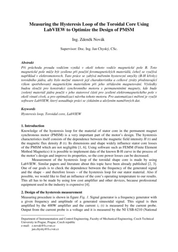
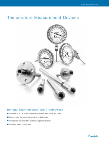
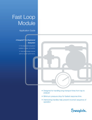
Fast LoopModuleApplication GuideA Swagelok Pre-EngineeredSubsystem Pre-engineered subsystemsavailable in weeks, not months. Field-tested design ensuresoptimum system performance. Designed for handling long transport lines from tap toanalyzer Minimum pressure drop for fastest response time Interlocking handles help prevent incorrect sequence ofoperation
Swagelok Pre-EngineeredSubsystemsContentsWhy Use aFast Loop Module? . . . . . . . . . 3Swagelok now offers a series ofpredesigned and preassembledsubsystems for use in all types ofplants and facilities where fluids arebeing processed. Use Swagelok preengineered subsystems to create fullydocumented fluid sampling and controlsystems and bring consistency to youroperations. Easy to install and operate,these subsystems offer the high qualityand support you expect from Swagelok.Key Features . . . . . . . . . . . . . . . 4Configurations . . . . . . . . . . . . . . 4Options . . . . . . . . . . . . . . . . . . . 9Where to Install aFast Loop Module . . . . . . . . . 10How to Select aFast Loop Module . . . . . . . . . 11Materials of Construction . . . . . . . 12Pressure-TemperatureRatings . . . . . . . . . . . . . . . . . . 13Testing . . . . . . . . . . . . . . . . . . . . . 13Cleaning and Packaging . . . . . . 13Flow Data . . . . . . . . . . . . . . . . . 14Dimensions . . . . . . . . . . . . . . . . . 17Ordering Information . . . . . . . . . . 19Regulatory Compliance . . . . . . . 20
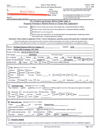
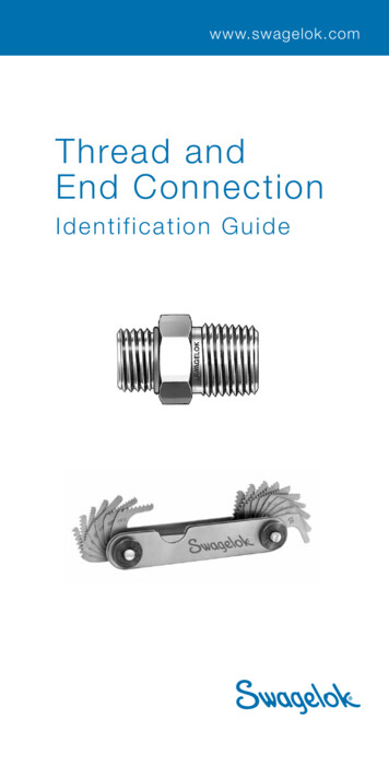
3The SwagelokFast Loop Module (FLM)Why Use a Fast Loop Module?Fast loop modules are designed to handle high flows in sample transport lines to reduce timedelays for online analyzer systems. Located at the analyzer shelter and offering a bypass, theSwagelok fast loop module (FLM) can isolate the sample system and introduce a purge gas forsystem cleaning. The FLM extracts a sample through a filter while using the high flow rate of thebypass to keep the filter element clean.Get a Faster ResponseThe distance between a sample tap and ananalyzer can make it difficult to obtain a usefulanalytical measurement. Sample transport linesare commonly more than 100 feet (30 meters) oftubing or pipe and require high purge volumesto ensure a fresh sample reaches the analyzer.Ideally, the flow from the sample tap to theanalyzer shelter should take one minute or less.Depending on the tubing or pipe size of theTypical Swagelok Fast LoopModule (FLM)transport lines, as well as the actual transportdistance, this flow rate could be as high as 90 std ft3/h (2548 std L/h). See Flow Data,page 14, for guidelines on sample transport volume.Minimize Sample WasteA Swagelok FLM also minimizes the amount of extracted sample that is sent to flare or disposal.A bypass filter specially designed for fast loop systems enables the FLM to provide high flowrates. The filter bypasses much of the sample flow and returns it to the process line through asecondary transport line. To generate high flow rates through this bypass loop, the return pointmust be at a lower pressure than the extraction point.To further reduce sample waste, many Swagelok FLM configurations offer a sample return linefrom the analyzer (configurations 2, 3, and 4). This option eliminates sending any continuous flowfrom an online analyzer to flare or disposal.A Swagelok Pre-Engineered SubsystemFast Loop Module.
4Key FeaturesDesigned to optimize online analyzer performance, Swagelok pre-engineered subsystems arefully tested for component performance, system integrity, and fluid flow prior to shipment. Acomplete pre-engineered subsystem can be configured and ordered using a single orderingnumber, so order and delivery is simple and fast. All Swagelok pre-engineered subsystemsare backed by the Swagelok Limited Lifetime Warranty and supported by Swagelok sales andservice representatives.Interlocking HandlesThe Swagelok FLM includes two ball valves that switch flow to a bypass to isolate the samplesystem and analyzer during maintenance. These bypass valves maintain flow through the fastloop to keep the sample fresh at the bypass point. An innovative interlocking handle systemallows for simultaneous actuation of the valves, while allowing for packing adjustments withinan individual valve body. In some configurations, the drain and purge valves are locked into thebypass valves to eliminate the possibility of opening the drain or purge lines while the system isin sample mode. All handles can be locked into position to eliminate the possibility of accidentalactuation.Easy MaintenanceDesigned to enable easy access to any component without disturbing other components in thesystem, the Swagelok FLM uses welded assemblies to reduce potential leak points and zeroclearance fittings in straight run tubing sections.Virtually Eliminates Water HammerClosing a valve in a high-flow liquid line causes extreme pressure spikes, referred to as waterhammer, which can damage system components. The Swagelok FLM eliminates the possibilityof water hammer by making full shutoff impossible. The bypass valves actuate simultaneouslyto eliminate the possibility of actuating only one of the valves. The three-way valve design allowsflow to switch gradually from sample mode to bypass mode, instead of temporarily shutting offduring actuation.ConfigurationsThe FLM base configuration is the framework for all FLM subsystems. The other FLMconfigurations offer additional features to address specific system requirements.A Swagelok Pre-Engineered SubsystemFast Loop Module
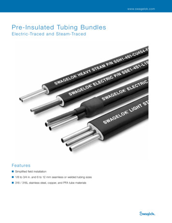
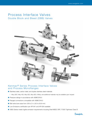
51. FLM Base Model, Bypass OnlyBecause it is important to maintain flow through the fast loop system even when the analyzer is notin service, all FLM subsystems feature dual interlocked ball valves (BV1 and BV2) that enable thefast loop to be bypassed when the analyzer is not in service. This key feature maintains flow throughthe fast loop system and improves overall system performance once the analyzer is back online.These bypass valves have been designed to include an interlocking handle, which providessimultaneous switching to bypass mode. Further, these valves are specially designed to ensurethe bypass opens before the sampling line closes,which eliminates the possibility of water hammer andpressure surges during switching.Swagelok offers FLM subsystems in two tubing sizes:the 1/4 in. size is used mainly for gas samples, and the1/2 in. size is usually best for liquid samples. The fastloop circuit monitors and controls flow through the useof an armored flowmeter (FI) and a needle valve (NV)for flow adjustment. This needle valve will be located1/2 in. Liquid System withOptional Grab Sample and ReliefOutlets Showndownstream of the flowmeter for liquid systems but ismoved upstream of the flowmeter in gas systems. Apressure gauge is included on the bypass side of the fast loop filter to eliminate the effect of agauge’s deadleg. As further protection, the fast loop pressure gauge on liquid systems has asintered snubber (SN) in the gauge inlet line to dampen its response to pressure 2CBV1PISN(Liquid)ToAnalyzerFFL The base model configuration is suitablefor gas or liquid samples.integral handles for simultaneous switching The high-flow armored flowmeter (Fl) andneedle valve (NV) provide flow indicationand adjustment.to bypass. A special flow pattern in the inlet/outlet valveseliminates water hammer during actuation. A high-efficiency, vortex-style filter (FFL) iscleaned by loop flow velocity. Inlet and outlet valves (BV1 and BV2) have Inlet pressure indication with or withoutliquid damping (PI) is placed on the bypassside of the filter to eliminate effects ofgauge dead space.A Swagelok Pre-Engineered SubsystemFast Loop Module.
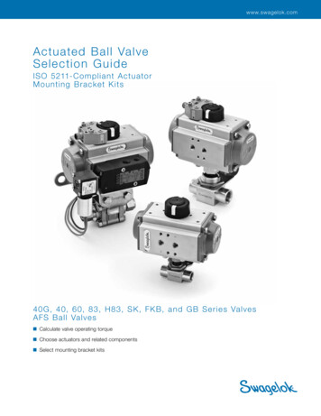
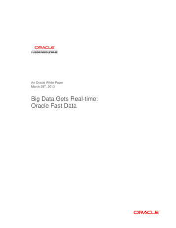
62. Return from Analyzer to ProcessIn this configuration, analyzed sample flow isreturned to the FLM from the analyzer and returnedto the process. This return line includes a checkvalve (CV) to prevent backflow to the analyzer. Note:The analyzer will work at full return pressure, whichmight not be appropriate for a gas sample.1/2 in. Liquid System with OptionalGrab Sample and Relief as)BV2CVCFromAnalyzerBV1PISN(Liquid)ToAnalyzerFFL This configuration includes all of the The sample is returned downstream ofadvantages of the base model and adds aflow control (NV) to minimize pressurereturn line from the analyzer to return thedifferential.fluid to process. A check valve (CV) prevents backflow toanalyzer.A Swagelok Pre-Engineered SubsystemFast Loop Module
73. Return from Analyzer Switch DrainThe system drain configuration includes a ball valve(BV3) to divert the returning sample to the drain. Thisconfiguration depressurizes the analyzer so that thecomplete sample flow path can be purged or flushedduring maintenance. The valve (BV3) is interlocked tothe bypass valves, ensuring that the system cannot beswitched to drain unless it is in bypass mode.1/2 in. Liquid System withOptional Grab Sample and ReliefOutlets uid)FFLToAnalyzerOilyDrain(Vent) An interlocked drain valve to bypass valves A connection is placed at the lowest pointallows the system to drain when in bypasson the system, allowing gravity to assist inmode.draining. The switching valve (BV3) on return from The drain port handle is locked closedthe analyzer line allows depressurizationwhen the inlet/outlet valves are in thethrough a drain port.sample mode and unlocked for drainingonly when the system is in bypass mode.A Swagelok Pre-Engineered SubsystemFast Loop Module.
84. Gas or Liquid Purge, Manual DrainThis configuration uses an inert gas or solvent topurge the process fluid from the flowmeter (FI) andfilter (FFL) housing and is useful when a filter elementneeds to be changed or cleaned.When used in conjunction with the return fromanalyzer line configuration, the purge configurationallows users to flush the remainder of the analyticalsample system downstream of the FLM. The purge1/2 in. Liquid System withOptional Grab Sample and ReliefOutlets Shownvalve (BV4) is mechanically linked to the drain valve(BV3) so that both valves can be actuatedsimultaneously. It is also interlocked with the bypass valves (BV1 and BV2) to eliminate anychance of actuating the purge and drain valves unless these two valves are switched to bypassmode. Downstream of the filter an additional connection to drain is included to ensure fullsystem purging. This drain line includes a manual valve (PV) and check valve (CV2) to preventbackflow from the drain or rCBV1BV3PISN(Liquid)FFL This configuration allows for purge inletToAnalyzerOilyDrain(Vent) A purge connection allows a positivethrough an additional interlocked valvepressure purge fluid to flush the entirethat can only be actuated when in bypasssystem to the drain, for most effectivemode.system drainage. The purge valve (BV4) is connected to thedrain valve (BV3) to ensure simultaneousaction.A Swagelok Pre-Engineered SubsystemFast Loop Module
9OptionsAn optional grab sample outlet and a relief outlet are available with all FLM eliefOutletFFLRV Located downstream of the bypass valves,ToAnalyzerOilyDrain(Vent) An optional pressure relief valve (RV)the sample outlet with a rotary shutoffprotects the gauge and flowmeter fromvalve (NV3) allows for sample collectionexcessive pressure.even when the FLM is in bypass mode formaintenance.A Swagelok Pre-Engineered SubsystemFast Loop Module.
10Where to Install a Fast Loop ModuleFast (Vent)ProcessAnalyzerASampleReturnOptionAnalyzer LocationProbeReturnTapThe schematic above illustrates an FLM installed in an analytical system. A fast loop needs twoprocess taps: one for sample supply and one for sample return. To avoid the cost of a samplepump and improve sampling system reliability, select a return point location that has lower pressurethan the supply tap. Choose process tap locations that are as close to the analyzer as possible.If the sample contains a condensable gas, heat the fast loop lines and the FLM above the dewpoint temperature of the sample at process pressure. A liquid sample will need to be heated onlyif it is necessary to keep from freezing.A Swagelok Pre-Engineered SubsystemFast Loop Module
11How to Select a Fast Loop ModuleTubing SizeSwagelok offers the FLM in two tubing sizes. The 1/2 in. system, which uses 1/2 in. tubing andfittings, offers less flow resistance (higher Cv) and, therefore, is more suitable for liquid samples.The 1/4 in. version is intended mainly for gases.End ConnectionsAll systems include a 1/8 in. (3 mm) connection to the analyzer line and a 1/4 in. (6 mm)connection to the purge drain. Half-inch systems include 1/2 in. (12 mm) fast loop and drainconnections. Quarter-inch systems include 1/4 in. (6 mm) fast loop and drain connections.Pressure GaugeThe pressure gauge is available with 63 or 100 mm (2 1/2 or 4 in.) dial, control ranges from 0 to150 bar (0 to 2175 psi), and with or without damping.FlowmeterThe standard flowmeters for liquid samples are calibrated for water flow. The standardflowmeters for gas samples are calibrated for air at 20 C and 1 bar (absolute).Filter ElementChoose a filter size based on the filtration needed from the element. Pore sizes from 2 to 50 μmare available.For more information about installation, operation, and maintenance of Swagelok FLMsubsystems, see the Fast Loop Module User’s Manual, MS‑13‑219.A Swagelok Pre-Engineered SubsystemFast Loop Module.
12Materials of ConstructionAll wetted metal components are 316 stainless
Because it is important to maintain flow through the fast loop system even when the analyzer is not in service, all FLM subsystems feature dual interlocked ball valves (BV1 and BV2) that enable the fast loop to be bypassed when the analyzer is not in service. This key feature maintains flow through the fast loop system and improves overall system performance once the analyzer is back online .