Transcription
AltiumLive 2018University DayInstructorDerek Jackson CID Product Expert
Altium Designer Best PracticesAltium Designer Best PracticesA look at best practice in Altium Designer.
Altium Designer Best PracticesCommunication1. Assembly House2. Fab Houses3. EE, PCB designers, CAD Department1. Add notes into your schematics (Place » Note / Text Frame).2. Add notes on your Mechanical Layers in PCB.4. Datasheets5. Web Forums6. Peers7. Technical Support
Altium Designer Best PracticesStandardization1. Designs and Projects Using Templates2. Standardize libraries3. Naming conventions
Altium Designer Best PracticesOrganization1. Librariesa. Usage and location.b. Component Parameters2. Supplier Linksa. Add a manufacturer / mfg part number parameter toyour components3. Template locations.4. Design locations
Altium Designer Best PracticesBackups1. Use Version Control2. Make backups3. Save Often
Altium Designer Best PracticesKnow the toolMost of us wear many hats.However, we might also work with other departments/teams or, may not use the same documents inAD every day, e.g., working on the schematic portion for several weeks before moving to PCB, so theday in and out can be forgotten.The following slides contain a number of of notes I made of tidbits I remembered during my workingon a project, although it may not be fully comprehensive, hopefully there is something that you mayfind beneficial. It is up to you to dig in and create your own best practices that best suit you needs.
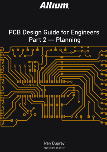
Altium Designer Best PracticesPieces: PCB KitchenBreakdown of sections covered:-Altium LiveSystem LevelSchematicLibraryPCBFabrication / Assembly
Altium Designer Best PracticesAltium Live:The first thing to know is how to find help. There are several resources availableForums, Documentation, Support, and Resources (and Web searches)Forums: (Help » User Forums)Use Advanced and search Topics to help visually parse search results
Altium Designer Best PracticesAltium Live:Documentation: (Help » Exploring AltiumDesigner or F1)-All documentation is online.Select the your Altium Designer VersionClick the magnifying glass to enter searchkeywords, or use sidebar to navigate.Web Search:Search Online, and bookmark useful entries.In Google, enter “Altium” in double quotesplus any keywords. Or, use your favoritebrowser search engine.
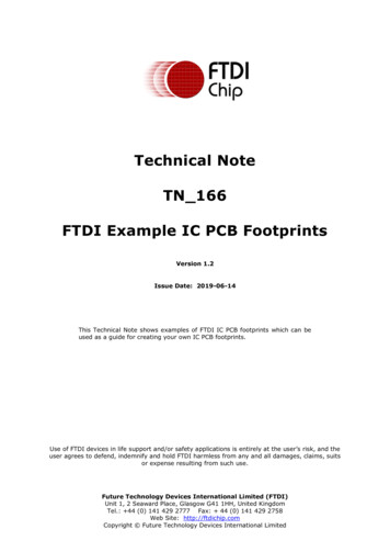
Altium Designer Best PracticesAltium Live:Support:(“Altium Live: Resources » Support”)After searching, if you still needhelp and cannot find the answers,enter a Support Cases online.If you have entered a case andhave posted in the communityforums about the same issue,make sure to add your forum linkin your case.
Altium Designer Best PracticesSupport:Bug Crunch / Ideas:If it results in being a feature request or abug, search in the Bug / Ideas section andvote or enter a new item.This is a community driven area that R&Dreferences when they are trying to decideon what issues/requests they will fix, soyour vote really does help (although it mayappear otherwise).
Altium Designer Best PracticesSupport:Bug Crunch / Ideas:Make sure to updateyour support case withthe BC or Idea link so itcan be linked and addedto the internal R&Dticket.If there is a similarreport, click the votebutton.
Altium Designer Best PracticesSupport:Bug Crunch/Idea Comments:Make sure to read throughthe comments on reportedBugs/Ideas and give athumbs up / down, as theremay be a workaround, or thecommand was being usedincorrectly.
Altium Designer Best PracticesSystem 18.0/display/ADES/Altium Designer - ((System Requirements))Video Card DirectX gaming style Video CardMore RAM (4-64Gb)* Be mindful of Power requirements* Read reviews on cards if using 4KWhich card?Fast frequency, minimum 700GFlopsAMD Radeon RX Vega (10 TeraFlops)Nvidia GeForce GTX 1070/1080 (boasts 6.5/8.9 TeraFlops)System RAMMore is better, minimum is 4Mb. 16/32Mb preferred if you run other memory hungry applicationsconcurrently.CPUFaster CPU speed is better.Hard DrivesSSD is better for overall system performance
Altium Designer Best PracticesSystem:PanelsWith a document in focus, press the K key toaccess to panels selection on your cursor. ThePanel button can also be pressed. All panelsare available from ‘Views » Panels’.Save/Reset panel layouts in the ‘Preferences» System » View’. Save, Load, restore panelconfigurations here.Project PanelThe Project Panel populates withcomponents & Nets sections. These aresearchable as well as document names bytyping in the search fieldfor schematics forselected project.
Altium Designer Best PracticesSystem:PanelsNavigator Panel: Use inconjunction with the ProjectNets/Components section.After a compilation, openthe navigator panel tonavigate to nets orcomponents.Use the Flattened Hierarchysection to see all nets,otherwise, select byschematic document.Alt Click to navigate to bothSch and PCB simultaneously.
Altium Designer Best PracticesSystem:Design Workspace (*.DsnWrk)It is important to Save your Design Workspace.If not saved, the workspace behaves as a virtual workspace, saving the projects that are loaded ONLYwhen exiting Altium Designer.The Design Workspace appears at the top of the Projects Panel. Using ‘File » New » Design Workspace’will close out all open projects. The new workspace will be a virtual one, not saved as a file untilmanually saved using the ‘Save Workspace As’ command. Opening the saved Workspace will load allassociated project with it. Once saved, the workspace will save with the ‘File » Save All’ command.Project Packager:Right-click on a project to create a time stamped archive of your project. You can also include outputand history files, and can find tune which files get added. In order to archive the entire workspacearchived, the workspace must have been saved previously.
Altium Designer Best PracticesSystem:ShortcutsCarl Schattke said in last yearsAltium Live 2017, “know them,learn them, and use them!”In Altium Designer, in the searchfield, type in Shortcuts (shows forselected document type).Or, enter in ‘Shortcuts keyword’ tonarrow down the display).
Altium Designer Best PracticesSystem:ShortcutsAdditionally, all shortcuts aredisplayed in Altium play/ADES/Altium Designer ((Shortcut Keys))(On the Web page, underShortcut Listings, under eacheditor type are a number ofkey combinations, such asCtrl D to access the ViewConfiguration panel in PCB).
Altium Designer Best PracticesSystem:Accelerator KeysIn menus, the underlined lettercan be pressed directly for themenu to pop onto your cursor.Subsequent keystrokes will selectthe additional submenu orcommand.For example Pressing U, then Mwill start the Interactive MultiRouting command.
Altium Designer Best PracticesSystem:PreferencesThe mighty O key: Document specificlinks to most common preferences orpanels.
Altium Designer Best PracticesSystem:PreferencesImporting / Exporting Preferences willalso load in your menu customizations,including shortcuts.-The Search Field allows searchingfor keywords in preferences.-Autosave: “Data Management » Backup”. The default is off.Be in the habit of saving often. Enable this option just in caseyou forget.File Locking: “Data Management » File Locking”. In a sharedenvironment, enabling this in the preferences will only allowthe document to be opened in read only mode by otherdesigners.-
Altium Designer Best PracticesSystem:Active Bar vs the P (Place) key:- Active Bar settings are per document.- Bar entries can be modified (right-click on menu bar and select Customize)- Active Bar can be turned off (Preferences: System » General » Advanced » UI.UseActiveBar)- If disabling the ActiveBar, copy the selection filter to your menu bar first (in PcbDoc, SchDoc,Pcb/SchLib editors). The selection icon gets a green dot on it when a filter is applied.- To Copy: right-click next to the menu items and select customize.- Start Dragging then before releasing, press the Ctrl button so it makes a copy instead ofmoving when you release it.-A clear button can also be copied in a similar fashion by temporarily enabling the StandardToolbars (Sch: from Schematic Standard, Pcb: PCB Standard, Lib: Sch / Pcb Lib Standard)
Altium Designer Best PracticesSystem:Templates:‘Preferences » Data Management » Templates’Set a custom path OUTSIDE the version specific folder of Altium Public folders. Anycustom templates, files or modification in this location will be completely deleted inthe even of a complete uninstall of Altium Designer.
Altium Designer Best PracticesSystem:Templates:Schematic templates.These define the currentschematic document’stitle bar and allowsadding customdocument parameters.Using schematictemplates can helpstandardize informationprovided on yourschematics.Schematic templates can be updated and reapplied to schematic documents.
Altium Designer Best PracticesSystem:Templates:Project templates.“File » New » Project ” invokesthe project Wizard. The Wizardwill take a selected template, andclone it in the specified locationwith the given name. This definesa starting project and can includeone or more schematics and pcbdocuments.Several templates are provided asexamples at Altium Live’s DesignTemplate Design Resourcesection. Download and modify tofit your requirements.
Altium Designer Best PracticesSystem:Templates:Use the Project Options’ “Options” tab to setup template locationsthat are specific to the project. Enter the path location in the“Schematic Template Loction” field.
Altium Designer Best PracticesSystem:Version Control:SVN or GIT (Git is available in AD18revision and later). Both can be usedwith either a Local or Remoterepository.For GIT, there is no added extension,just checkout the project from yourNEXUS Server, or from a GIT repousing your favorite GIT client, andAltium Designer will recognize it is inGIT.For SVN, configure the repository in“Data Management » DesignReporitories”.
Altium Designer Best PracticesSystem:Storage Manager: Access from Panelsbutton. This panel shows commits aswell as the local save history for aselected document.In the Storage Manger, you cancompare document revisions, either inVCS or in Local History by Select tworevisions and right-click to comparedifferences.Make sure to purge your local historyonce in awhile, especially if you saveoften. Adding comments to files in thehistory, you can exclude commentedhistory files from being purged.
Altium Designer Best PracticesSystem:Troubleshooting:Hold the Ctrl key whilestarting Altium Designer (thiscan help resolve crashes onstartup by preventing opendocuments from reload).Uninstalling:For troubleshooting, for worstcase scenario when AltiumDesigner just will not start, tryuninstalling just thepreferences (this will reset allpreferences back to thedefaults). If possible, whenAltium Designer is running,export preferences first.
Altium Designer Best PracticesSystem:Troubleshooting:Projects:Ensure all design files are part of a projectand don’t end up in Free Documents (If adocument was opened, and the projectwas not saved when Altium Designerrestarted.Free Documents are for opened files that are not in a project and when closed, these are removedfrom the workspace.Projects specify ERC checking, ECO, output path locations.Schematics not in a project will have their ECO checks all default to error.
Altium Designer Best PracticesSystem:Registered File Types:Register/unregisterAltium Designer toopen specific filetypes.Or, if multiple versions areinstalled, register thefiletypes within theversion you wish tobe the default editorby checking / unchecking thecheckbox next to theextension.
Altium Designer Best PracticesSchematic:Units: In Schematic, mils/inches are best, don’t try metric (which is fine in PCB / PCB Library).Dragging:Hold CTRL key while dragging non-electrical schematic objects, such as text or component designators,to move by the smallest unit (10mil).Grids:Don’t use a 10mil grid for schematic design. Altium’s schematic components have a pin-to-pin spacing of100mil.Project Compilation:Errors and warnings, in the Message Panel, right-click cross probe to errors. Remember, the Messagepanel only auto opens for errors, not warnings. ALWAYS double-check the Message Panel, and read ALLwarning messages.
Altium Designer Best PracticesSchematic:Unconnected pins:Place NoERC on all no-connectpins. ‘Place » Directives »Generic NoERC’, or right-click onthe message in the MessagePanel and add a Specific No ERCto the pin.In the Project Options, set theConnection Matrix for ALLunconnected pins to Warnings.This is especially important if youhave imported a design in orderto verify connectivity
Altium Designer Best PracticesSchematic:Smart Paste:(pasting as other objects), for example,pasting a bus net label as wires, portsand net labels.Placement “inherit”:Use Insert key when placing Nets, andPorts when hovering over an existing textobject to pick up the name.Buses:Ensure net labels are placed on a Bus,and that they have the format:NETNAME[StartIndex#.EndIndex#]
Altium Designer Best PracticesSchematic:Hierarchal Design:- Sheet symbols can be used in both Flat andHierarchical designs.- For hierarchical designs, you can includesheets without sheet entries, such as theSL Power as shown in the image.- Power Ports: Don’t put ports on powerports (localization). These are global bydefault.- Decide up front if you are using Flat orHierarchical vs Multi-Channel before PCBtransfer, otherwise, it is difficult to matchup component links after parts are on thePCB.- All Sheet symbols need unique designators(currently, this is a manual process).
Altium Designer Best PracticesSchematic:Annotation:Leave designators ending in a question mark ?, e.g., U?.Annotate with ‘Tools Annotate Annotate Schematics Quietly.’. This will assign available designators.Full Annotation control is set in the ‘Tools » Annotate » Annotate Schematics ’.Board Level Annotation:Requires annotation at both schematic level and in Board Annotation Manager. This uses an external.ANNOTATION file. Ensure no duplicate designators in schematics prior to running.Do not invoke this command unless you read about it first here. There is a lot of good information onannotation in that link, so it is worthwhile to review the entire page.
Altium Designer Best PracticesSchematic:Rule Directives in the schematic:(can only specify Unary targets, binary assumes second object is All)- Width (Place » Directives » Parameter Sets). Make sure to select the Pcb Stackup to targetspecific layers.- Differential Pairs (requires end in N and P to differentiate). In AD18.1.6, “Diff Pair Classesin Schematics” was introduced in the directive settings!
Altium Designer Best PracticesSchematic:Net Classes:(Use blankets Place » Directives » Blankets for assigned nets in a grouped area). ‘Place » Directive »Parameter Set’ to place on a wire or blanket to assign associated net to the assigned class. The blanket is thedashed line around the net labels to be included in the class. The Netclass will transfer to the Pcb doc asshown.To Ensure your net classestransfer to the PCB, ensurethat the option is enabledin the project options,under the Class Generationtab: User Net Classes, aswe will see on the nextslide.
Altium Designer Best PracticesSchematic:Component Classes: Can be defined in the schematic, but require a Class Name parameter. Classes areautomatically generated per page, but sub classes can be made with parameters.Harness Classes:Enable the ‘GenerateNet Classes for NamedSignal Harnesses’ tocreate classes for eachnamed harness used inyour schematics.
Altium Designer Best PracticesSchematic:Net Colors: (these sync with the PCB). Helpful to track nets, and component orientation in PCB. Define ineither the Schematic or the PCB. From the Schematic, use ‘View » Set Net Colors’. From the PCB, use thePCB Panel’s Net section. Coloring ground can be very useful when orienting your coupling caps, as the defaultcolor is defined by the layer color (see all the power pads at a glimpse).
Altium Designer Best PracticesSchematic:Moving Components: (that have been transferred to PCB): Use Edit » Refactor » Move Selected Subcircuit ToDifferent Sheet). Cut and Paste will change the Unique ID. Although the default ECO option when updatingthe PCB will try and resync these using designators, if the designators have changed, it may result in yourcomponents getting ripped up and re-added off the board.Component Links:Although the ECO will check ifyour schematic and PCBcomponents are in sync, bestpractice is to manually checkonce in a while using ‘Project »Component Links’ from the PCB.When syncing, enable bothDesignator and footprint(comment can be helpful as wellto ensure a correct match).
Altium Designer Best PracticesSchematic:Page Numbering: Perform ‘Tools » Annotation » Number Schematic Sheets’ to ensure all sheets have uniquepage numbers (just a necessary step).Placement: When moving objects with the mouse, for auto scroll, use the arrow keys and hold Shift to movex10 speed in either SCH or PCB).Mechanical items:Place mechanical / fiducial / mounting holes/ test points / and the PCB item onschematicsPlace these on a schematic as a componentto include them in the Bill of Materials. Setthe Component Type to Mechanical if youonly want them to be included in the BOM,and not added to the PCB.
Altium Designer Best PracticesSchematic:Design Reuse:- Device Sheets:(also called Managed Sheets if used in conjunction with the Altium Vault / NEXUS Server). UsingManaged sheets is a good way to reuse a verified schematic document. The sheet does not live in yourproject, but is compiled into your project. Set the location of the Managed Sheet in the preferencesunder ‘Data Management » Device Sheets’.
Altium Designer Best PracticesSchematic:Design Reuse:- Device Sheets (Cont):place in the schematic similarly to a sheet symbol. Compiling pulls the sheet into your project asread-only, so it is necessary to use Board Level Annotation to annotate.
Altium Designer Best PracticesSchematic:Design Reuse:- Device Sheets (Cont):Manage the Sheet Symbol properties from theProperties panel.
Altium Designer Best PracticesSchematic:Design Reuse:When compiling your project,device sheets automatically syncwith source.It is more advantageous to use managed sheets inconjunction with the NEXUS server, as the sheets don’tautomatically update unless purposely, where regulardevice sheets update automatically to sync with changesmade to them.To freeze a Device Sheet for a particularproject, use ‘Edit » Refactor’ to convert itto a regular schematic sheet.
Altium Designer Best PracticesSchematic:Footprint Manager:‘Tools » Footprint Manager’.Verify footprints are availableand which libraries these arefound in.This helps ensure that librariesare configured correctly beforesending them to the PCB or thePCB Designer.
Altium Designer Best PracticesSchematic:Footprint Manager (Cont):Footprint locations can also be modified in theFootprint Manager dialog by clicking Edit. This isuseful if the design engineer used librariesconfigured with a path different to yourconfiguration.In the PCB Library section of the footprintsproperties, the option for Any can be selected,however, best practice is to specify a library name tohelp reduce the chance of the footprint from gettingpulled from the wrong library.
Altium Designer Best PracticesSchematic:Supplier Management:Create a ‘File » ActiveBomDocument’ early on in thedesign cycle.Suppliers are pulled fromAltium’s online supplierdatabase, Ciiva.This can give a glimpse onavailable supplier stock. This isa live document and will pull innew components as you buildyour design.Note: Only one ActiveBom is allowed per project, so if you don’t see if listed under File » New, chances are you alreadyhave one created for the project.
Altium Designer Best PracticesLibraries:Best practice is to use an Altium Vault / NEXUS Server, as this allows Revision management. This is a purchased productto be used with Altium Designer / NEXUS. The Server uses a one to many approach for component management, wherea single graphical symbol can be used in multiple components.Database Libraries, DbLibs, have a similar approach of one to many, whereas regular libraries are one to one. A one tomany, for example, one resistor symbol representing hundreds of resistor components. Database libraries are theapproach when transferring library components to a NEXUS server. DbLibs connect to any ODBC compliant database.Library Types:-Regular Schematic (*.SchLib) and Footprint (*.PcbLib)Database (*.DbLibs)Integrated (*.IntLibs)Integrated Libraries are a compiled, read-only files that combine several regular SchLib and PcbLibs into onefile. Note, however, each footprint must have a referencing schematic component in order to be accessed.
Altium Designer Best PracticesLibraries:Virtual Libraries:-Create a virtual library that referencesyour own Vault components (NEXUSServer), or Altium Content Vaultcomponents.-Just add the folders you wish to includein the library by selecting the Installfrom server. selection.
Altium Designer Best PracticesLibraries:Symbols / Footprints: Where do you find them?- Altium Content Vault / Altium Live- Legacy Integrated Libraries- Searching Manufacturer Web:- Downloaded supported CAD reference designs aslibraries can be generated from schematics or pcbs.‘Design » Make Library’- Sometimes Altium libraries are available fordownload- Octopart (click CAD Models from search and downloadif available)- IPC Footprint Wizard(Use Batch spreadsheets and save copy. )- Schematic Symbol Wizard- Other 3rd party sites / tools(always validate any downloaded library before use)
Altium Designer Best PracticesLibraries:3D Models: (a must for every footprint)It is easy to create extruded models. Orhave your CAD department provide a nicestep model or download from the Web.--Clearance checking: The 3D body isused for component to componentclearance.The extruded or step model is usedfor both vertical and horizontalclearance based on the step modelsshape.Easily created from bounding shapesin the Pcb Library editor using‘Tools » Manage 3D Bodies for ’
Altium Designer Best PracticesLibraries:3D Models (Continued):If a 3D Body (model) is not attached to yourfootprint, the entire bounding area is used.This area is calculated from all pad objectsand silk screen layers and can larger thanexpected, especially for odd shapedfootprints.-Use the IPC Wizard in a Pcb Library andenable the option to create a Stepmodel.- Download models from Web sites such as:3D-Content CentralGrabCAD
Altium Designer Best PracticesPCB:Top 5 items to know: owSelection Filter:Green indicator shows there is a filter appliedFilter menu still available with right click.The Filter also has a clear button which can be accessed directly or copied onto your toolbar if not using thefilter toolbar.PCB Panel:Used to navigate / zoom / select items in your PCB (use DIM with [ ] keys to increase / decrease intensity)For components, right-click in the primitives section to enable more primitive displays.Good method for manually assigning nets to objects in the case of updating footprints from libraries containingnew primitives, these don’t always get updated.Alternate methods for net propagation is using ‘Design Netlist update free primitives from componentpads’Configure Physical Nets is another option, but EXTREME caution needs to be used, as you can rename netsunintentionally, so if you use it, make sure you look at every single proposed change.Dragging in PCB: Use the CTRL key to override snap when dragging. (Shift E to toggle Hotspot snap settings).
Altium Designer Best PracticesPCB:ECO:Make sure you look at theproposed changes whenyou execute an ECO onyour PCB Design, ‘Design »Update PCB Document’.Un-check anything youdon’t want added,changed, modified, orremoved. Right-click in asection and select ‘DisableAll of Same Kind’ to disableall entries for that section.
Altium Designer Best PracticesPCB:Project » Component Links:As mentioned before, always doublecheck to ensure all placed componentsare matched up and in the rightmostsection.These can be matched manually, enablecomment and footprint check-boxes(unless footprint has changed inschematic symbol).This is automatically checked during theECO. I prefer to select Manual andvisually verify what is getting linked.
Altium Designer Best PracticesPCB:Rules:Rules & Violations Panel: Use to easily run DRC checks and finderrors.Use the PCB Rules & Violations to quickly find DRC errors.Right-click on a rule, or a rule class and run just that rule. Thisis a great time saver when only one rule needs to be checkedrather than running a full DRC check using ‘Tools » Design RuleCheck’.Best practice is to start checking design rules early and keepthem in check throughout the design cycle.DO NOT disable rules in the PCB Rules & Violations Panel, thisshould only be done in the Design Rule Check Dialog.
Altium Designer Best PracticesPCB:Rules:When defining rules, ‘Design» Rules’, target componentor net classes, not a specificdesignator or net.Changing a net name in yourdesign DOES NOT update therule to reflect the new name.Using a Net Class, unless thenet class name changes, thenet class will alwaysencompass the targeted netsin the rule.
Altium Designer Best PracticesPCB:Colors:As mentioned before,using Net Colors greatlyenhances the visibility ofnet locations in the PCB.Enable the Net colorOverride in the PCB Panelby checking the box to theright of the Net name isorder to override the layercolor for that net.
Altium Designer Best PracticesPCB:Layer sets: (L) View Configuration Panel. Useto quickly turn on / off layers (auto mirrordisplayed layers can be enabled also).Clicking the LS button at the lower right ofthe Pcb workspace allows selection fromavailable Layer Sets.Create and save your own Layer Setsto quickly enable only the layers you need towork on or that are related to a specific netrouting.
Altium Designer Best PracticesPCB:View Configurations: ‘(L) » View Options’ Save your Draft /Transparent settings.--Create View Configurations to quickly apply the saved settingsin your View Configuration Panel. Some available settings areavailable as examples, such as ‘Altium Transparent 2D’.Once you have set the object visibility (unclick the eyeball tohide objects), set the Transparency slider, and checked the boxfor objects to display in Draft, save your settings in a customconfiguration.Other useful settings to enable are:- Repeated net labels on tracksMask and Dim Settings allow you to adjust the mask applied from afilter. With the a PCB document selected, change the intensity ofdimmed/masked objects using the ([ , ] shortcuts).
Altium Designer Best PracticesPCB:Other useful commonly used commands to help productivity:-Measure selected: to display length of selected tracks. (Use xSignals for more accurate calculations).-Hiding Connections: Hide nets with lots of connections, like ground, to speed up net analysis delays(improved in 18).-Moving components: Connections lines are hidden for more than 50 pad components, change inadvanced preferences. This controls the dynamic connections and is useful for moving and orientingcomponents.- Press Space bar to rotate component while moving- Press the L key to flip from Top to Bottom.Deleting tracks: Press Ctrl backspace to extend delete selection (deletes selected track and selects adjacentsegments).Selection: Press Tab to extend a selection of a selected track. Press Tab again to extend selection to pads andopposite multiple layers.Picking up net: Paste a via onto a track end, the via picks up the net of the track.
Altium Designer Best PracticesPCB:Polygons: always repour (or not) user preference(Preferences » PCB Editor » Repour PolygonsAfter Modification’.Use ‘Tools » Polygon Pours » Shelve’ (totemporarily hide polygons for movingobjects/routing an area that may be obscured.Use the Polygon Manager to manage pours.Click the Auto Generate button to order thepours based on size (smallest to largest). Amust if working with an imported board.Use the Auto Assign Name option to autoname polygons. This will use the layer and netname. Control the naming scheme option atthe bottom of Properties Panel when nothingis selected.
Altium Designer Best PracticesPCB:Dimensions: Best practice is to ALWAYS add dimensions to your board (on a mechanical layer), especially forthe board shape. Don’t assume the Fab knows, otherwise, you might unexpectedly get back the wrongboard size).Unions: Use to lock objects relative to each other. (view unions in PCB Panel’s Union section).Zooming: Since you mostly right-mouse to drag and pan your PCB workspace, to zoom, keep the right-mousepressed and press and simultaneously click and hold the Left mouse. Once the cursor changes, moveyour mouse up/down to zoom in and out. (Same operation as Control Right-mouse-button, or easiestway to zoom is to just press the Center Mouse button, and move the mouse up or down to zoom in/out).
Altium Designer Best PracticesPCB:Routing:Enable Clearance Boundaries for bettervisual of routable spaces.Press the tilde key, , to get a list ofshortcuts during an activecommand.Pay attention to route mode in theHeads up display, also at thebottom of the workspace.
Altium Designer Best PracticesPCB:Locking:- Components:Lock all components after placement,prior to routing to prevent accidentalmovement- Routing:Once a route is finalized, lock it down(use the Tab extend method or FilterPanel).Use the filter panel to select items tolock, then us
Altium Live: Support: (“Altium Live: Resources » Support”) After searching, if you still need help and cannot find the answers, enter a Support Cases online. If you have entered a case and have posted in the community forums ab