Transcription
NIST GCR 10-917-5NEHRP Seismic Design Technical Brief No. 4Nonlinear Structural AnalysisFor Seismic DesignA Guide for Practicing EngineersGregory G. DeierleinAndrei M. ReinhornMichael R. Willford
NEHRP Seismic DesignTechnical BriefsNEHRP (National Earthquake Hazards Reduction Program) TechnicalBriefs are published by NIST, the National Institute of Standards andTechnology, as aids to the efficient transfer of NEHRP and otherresearch into practice, thereby helping to reduce the nation’s lossesfrom earthquakes.National Institute ofStandards and TechnologyThe National Institute of Standards and Technology (NIST) is a federaltechnology agency within the U.S. Department of Commerce thatpromotes U.S. innovation and industrial competitiveness by advancingmeasurement science, standards, and technology in ways that enhanceeconomic security and improve our quality of life. It is the lead agencyof the National Earthquake Hazards Reduction Program (NEHRP). Dr.John (Jack) R. Hayes is the Director of NEHRP, within NIST’s Buildingand Fire Research Laboratory (BFRL). Dr. Kevin K. F. Wong managedthe project to produce this Technical Brief for BFRL.NEHRP Consultants Joint VentureThis NIST-funded publication is one of the products of the work ofthe NEHRP Consultants Joint Venture carried out under ContractSB 134107CQ0019, Task Order 69195. The partners in the NEHRPConsultants Joint Venture are the Applied Technology Council (ATC) andthe Consortium of Universities for Research in Earthquake Engineering(CUREE). The members of the Joint Venture Management Committeeare James R. Harris, Robert Reitherman, Christopher Rojahn, andAndrew Whittaker, and the Program Manager is Jon A. Heintz. Assistingthe Program Manager is ATC Senior Management Consultant David A.Hutchinson, who on this Technical Brief provided substantial technicalassistance in the development of the content.About The AuthorsGregory G. Deierlein, Ph.D., P.E., is a faculty member at StanfordUniversity where he specializes in the design and behavior of steel andconcrete structures, nonlinear structural analysis, and performancebased design of structures for earthquakes and other extreme loads.Deierlein is the Director of the John A. Blume Earthquake EngineeringCenter at Stanford. He is active in national technical committees involvedwith developing building codes and standards, including those of theAmerican Institute of Steel Construction, the Applied Technology Council,and the American Society of Civil Engineers.Applied Technology Council (ATC)201 Redwood Shores Parkway - Suite 240Redwood City, California 94065(650) 595-1542www.atcouncil.org email: atc@atcouncil.orgAndrei Reinhorn, Ph.D., S.E., is a professor at the University at Buffalo.He has published two books and authored two computer platforms(IDARC and 3D-BASIS) for nonlinear analysis of structures and forbase isolation systems. He has served as Director of the StructuralEngineering and Earthquake Engineering Laboratory at the Universityat Buffalo.Michael R. Willford, M.A., C.Eng. is a Principal of the global consultingfirm Arup with 35 years experience of design of structures for buildings,civil, and offshore projects in many parts of the world. A specialist instructural dynamics, he is leader of Arup’s Advanced Technology andResearch practice, specializing in the development and application ofinnovative design techniques using performance-based methods.About the Review PanelThe contributions of the three review panelists for this publication aregratefully acknowledged.Graham H. Powell, Ph.D., is Emeritus Professor of StructuralEngineering, University of California at Berkeley and was a lecturer inCivil Engineering, University of Cantebury, New Zealand, 1961-1965. Heis a consultant to Computers and Structures Inc., publisher of his textModeling for Structural Analysis. He has special expertise in seismicresistant design and the modeling of structures for nonlinear analysis.Finley A. Charney, Ph.D., P.E., is an Associate Professor in theDepartment of Civil and Environmental Engineering at VirginiaPolytechnic Institute, Blacksburg, Virginia, and is President of AdvancedStructural Concepts, Inc., also located in Blacksburg. Prior to joiningVirginia Tech in 2001, Charney accumulated twenty years of experienceas a practicing structural engineer. He is the author of many publicationson the application of structural analysis methods in seismic design.Mason Walters, S.E., is a practicing structural engineer and a principalwith Forell/Elsesser Engineers, Inc. in San Francisco. Walters hasbeen in private practice for over 30 years, focusing on the applicationof the seismic protective systems for numerous significant buildingsand bridge projects. Examples of these projects include the elevatedBART/Airport Light Rail Station at San Francisco International Airport,and the seismic isolation retrofit of the historic Oakland City Hall. Manyof Mr. Walters’ projects have incorporated nonlinear dynamic and staticanalysis procedures.Consortium of Universities for Research inEarthquake Engineering (CUREE)1301 South 46th Street - Building 420Richmond, CA 94804(510) 665-3529www.curee.org email: curee@curee.org
NIST GCR 10-917-5Nonlinear Structural AnalysisFor Seismic DesignA Guide for Practicing EngineersPrepared forU.S. Department of CommerceBuilding and Fire Research LaboratoryNational Institute of Standards and TechnologyGaithersburg, MD 20899-8600ByGregory G. Deierlein, Ph.D., P.E.Stanford UniversityStanford, CaliforniaAndrei M. Reinhorn, Ph.D., S.E.University at Buffalo, SUNYBuffalo, New YorkMichael R. Willford, M.A., C.Eng.ArupSan Francisco, CaliforniaOctober 2010U.S. Department of CommerceGary Locke, SecretaryNational Institute of Standards and TechnologyPatrick Gallagher, Director
Contents1.2.3.4.5.6.7.8.9.Introduction.1Nonlinear Demand Parameters and Model Attributes.4Modeling of Structural Components.12Foundations and Soil Structure Interaction.19Requirements for Nonlinear Static Analysis.21Requirements for Nonlinear Dynamic Analysis.23References.27Notations and Abbreviations.30Credits.32DisclaimersThe policy of the National Institute of Standards and Technology is to use the International System of Units (metric units) in all of itspublications. However, in North America in the construction and building materials industry, certain non-SI units are so widely used insteadof SI units that it is more practical and less confusing to include measurement values for customary units only in this publication.This publication was produced as part of contract SB134107CQ0019, Task Order 69195 with the National Institute of Standards andTechnology. The contents of this publication do not necessarily reflect the views or policies of the National Institute of Standards andTechnology or the US Government.This Technical Brief was produced under contract to NIST by the NEHRP Consultants Joint Venture, a joint venture of the AppliedTechnology Council (ATC) and the Consortium of Universities for Research in Earthquake Engineering (CUREE). While endeavoring toprovide practical and accurate information in this publication, the NEHRP Consultants Joint Venture, the authors, and the reviewers donot assume liability for, nor make any expressed or implied warranty with regard to, the use of its information. Users of the informationin this publication assume all liability arising from such use.Cover photo – Nonlinear analysis model for a seismic retrofit study of an existing building with concrete shear walls.How to Cite This PublicationDeierlein, Gregory G., Reinhorn, Andrei M., and Willford, Michael R. (2010). “Nonlinear structural analysis for seismic design,” NEHRPSeismic Design Technical Brief No. 4, produced by the NEHRP Consultants Joint Venture, a partnership of the Applied Technology Counciland the Consortium of Universities for Research in Earthquake Engineering, for the National Institute of Standards and Technology,Gaithersburg, MD, NIST GCR 10-917-5.
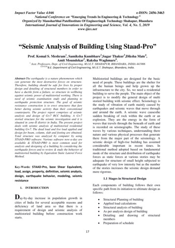
1. Introduction1.1 The Role and Use of NonlinearAnalysis in Seismic DesignSidebar 1Performance Levels and Acceptance CriteriaWhile buildings are usually designed for seismic resistanceusing elastic analysis, most will experience significant inelasticdeformations under large earthquakes. Modern performancebased design methods require ways to determine the realisticbehavior of structures under such conditions. Enabled byadvancements in computing technologies and available testdata, nonlinear analyses provide the means for calculatingstructural response beyond the elastic range, including strengthand stiffness deterioration associated with inelastic materialbehavior and large displacements. As such, nonlinear analysiscan play an important role in the design of new and existingbuildings.The earthquake performance of buildings generallyrelates to damage incurred to the building’s structure,envelope, partitions, ceilings, mechanical/electricalsystems, and contents. While the building performanceis a continuum, for design purposes it is convenientto identify discrete performance levels for the majorstructural and other building components that significantlyaffect building function, property protection, and safety.ASCE 41 (ASCE 2007) and other standards generallyprovide guidance on three performance levels: Immediate Occupancy – Achieve essentially elasticbehavior by limiting structural damage (e.g., yieldingof steel, significant cracking of concrete, andnonstructural damage.)Nonlinear analyses involve significantly more effort toperform and should be approached with specific objectives inmind. Typical instances where nonlinear analysis is appliedin structural earthquake engineering practice are to: (1) assessand design seismic retrofit solutions for existing buildings; (2)design new buildings that employ structural materials, systems,or other features that do not conform to current building coderequirements; (3) assess the performance of buildings forspecific owner/stakeholder requirements (Figure 1-1). If theintent of using a nonlinear analysis is to justify a design thatwould not satisfy the prescriptive building code requirements,it is essential to develop the basis for acceptance with thebuilding code authority at the outset of a project. The designbasis should be clearly defined and agreed upon, outlining inspecific terms all significant performance levels (Sidebar 1)and how they will be evaluated.(a) Life Safety - Limit damage of structural andnonstructural components so as to minimize therisk of injury or casualties and to keep essentialcirculation routes accessible. Collapse Prevention – Ensure a small risk of partialor complete building collapse by limiting structuraldeformations and forces to the onset of significantstrength and stiffness degradation.ASCE 41 provides acceptance criteria in terms ofdeformation and force demands on individual structuralcomponents. Other demand parameters (especiallystory drifts and floor accelerations) are also importantindicators of damage to nonstructural components andoverall building performance (PEER 2010; Willford etal. 2008; PEER/ATC 2010; ATC 2009). Moreover, theremay be other significant performance limits (such asonset of damage to the building envelope) that havemajor implications on lifecycle cost and functionality.While the risk (or likelihood) of exceeding the damagespecified in performance levels is predicated by buildingoccupancy and other factors, for typical buildings, i.e.,Occupancy Category II in ASCE 7 (ASCE 2010), it isgenerally accepted to check the Collapse Preventionperformance level for the Maximum ConsideredEarthquake ground motion intensity and Life Safetyfor the Design Basis Earthquake (defined as 2/3 of theMaximum Considered Earthquake intensity in ASCE 7).The appropriate ground motion intensity for checkingImmediate Occupancy is less well-defined, since thisperformance level is not typically addressed in buildingcodes.(b)Figure 1-1 – New headquarters of San Francisco Public UtilityCommission Building designed using nonlinear response history analysisto meet stringent immediate occupancy performance criteria.Sidebars in the guideSidebars are used in this Guide to illustrate key points,and to provide additional guidance on good practices andopen issues in analysis, design, and construction.Nonlinear Structural Analysis For Seismic Design: A Guide for Practicing Engineers1
Once the goals of the nonlinear analysis and design basis aredefined, the next step is to identify specific demand parametersand appropriate acceptance criteria to quantitatively evaluate theperformance levels. The demand parameters typically includepeak forces and deformations in structural and nonstructuralcomponents, story drifts, and floor accelerations. Other demandparameters, such as cumulative deformations or dissipatedenergy, may be checked to help confirm the accuracy of theanalysis and/or to assess cumulative damage effects.deformations as well as forces. They also require definition ofcomponent models that capture the force-deformation responseof components and systems based on expected strength andstiffness properties and large deformations. Depending on thestructural configuration, the results of nonlinear analyses can besensitive to assumed input parameters and the types of modelsused. It is advisable to have clear expectations about thoseportions of the structure that are expected to undergo inelasticdeformations and to use the analyses to (1) confirm the locationsof inelastic deformations and (2) characterize the deformationdemands of yielding elements and force demands in nonyielding elements. In this regard, capacity design concepts areencouraged to help ensure reliable performance (Sidebar 2).While nonlinear analyses can, in concept, be used to tracestructural behavior up to the onset of collapse, this requiressophisticated models that are validated against physical teststo capture the highly nonlinear response approaching collapse.Since the uncertainties in calculating the demand parametersincrease as the structure becomes more nonlinear, for designpurposes, the acceptance criteria should limit deformationsto regions of predictable behavior where sudden strength andstiffness degradation does not occur.In contrast to linear elastic analysis and design methods thatare well established, nonlinear inelastic analysis techniques andtheir application to design are still evolving and may requireengineers to develop new skills. Nonlinear analyses requirethinking about inelastic behavior and limit states that depend onSidebar 2Capacity DesignCapacity design is an approach whereby the designerestablishes which elements will yield (and need tobe ductile) and those which will not yield (and will bedesigned with sufficient strength) based on the forcesimposed by yielding elements. The advantages of thisstrategy include:This Technical Brief is intended to provide a summary of theimportant considerations to be addressed, considering thecurrent capabilities of nonlinear analysis technologies andhow they are being applied in practice. The scope includesboth nonlinear static (pushover) and dynamic (responsehistory) analyses, but with the emphasis towards the latter.This guide is intended to be consistent with building codesand standards, however, as the use of nonlinear analysis fordesign is still evolving, there are many areas where detailsof the implementation are open to judgment and alternativeinterpretations. Finally, while this technical brief is concernedprimarily with buildings, the guidance can generally apply tononlinear analysis of other types of structures. Protection from sudden failures in elements thatcannot be proportioned or detailed for ductileresponse. Limiting the locations in the structure where expensiveductile detailing is required. Greater certainty in how the building will performunder strong earthquakes and greater confidence inhow the performance can be calculated. Reliable energy dissipation by enforcing deformationmodes (plastic mechanisms) where inelasticdeformations are distributed to ductile components.1.2 Background on Use of NonlinearAnalysis in Building Design in the USAThe first widespread practical applications of nonlinear analysisin earthquake engineering in the USA were to assess andretrofit existing buildings. The first significant guidelines onthe application of nonlinear analysis were those published inFEMA 273 NEHRP Guidelines for the Seismic Rehabilitationof Buildings (FEMA 1997) and ATC 40 Seismic Evaluationand Retrofit of Concrete Buildings (ATC 1996). Owing to thestate of knowledge and computing technologies at the time oftheir publication (mid-1990s), these documents focus primarilyon nonlinear static (pushover) analysis. They have since beencarried forward into ASCE 41 Seismic Rehabilitation of ExistingBuildings (ASCE 2007), and improvements have been proposedin FEMA 440 Improvement of Nonlinear Static Seismic AnalysisProcedures (FEMA 2005) and FEMA P440A Effects of Strengthand Stiffness Degradation on Seismic Response (FEMAThe well known “strong column/weak beam” requirementis an example of a capacity design strategy, where theintent is to avoid inelastic hinging in columns that couldlead to premature story mechanisms and rapid strengthdegradation in columns with high axial loads. Thedesign of yielding links and elastic braces in eccentricallybraced frames is another example of capacity design.Where inelastic analysis is used, capacity design can beimplemented by modeling the specified yielding elementswith their “expected” strengths and the protectedelements as elastic. This permits the determination ofand design for the maximum expected force demandsin the protected elements.Nonlinear Structural Analysis For Seismic Design: A Guide for Practicing Engineers2
2009a). Note that while ASCE 41 and related documents havea primary focus on renovating existing buildings, the nonlinearanalysis guidance and component modeling and acceptancecriteria in these documents can be applied to new buildingdesign, provided that the chosen acceptance criteria provideperformance levels expected for new building design in ASCE7 (Sidebar 1).Cyclic Envelope: Curve of generalized force versusdeformation that envelopes response data obtained from cyclicloading of a structural component or assembly.About the same time that FEMA 273 and ATC 40 were underdevelopment, nonlinear analysis concepts were also beingintroduced into methods for seismic risk assessment, the mostwidely known being HAZUS (Kircher et al. 1997a; Kircher etal. 1997b; FEMA 2006). In particular, the building-specificloss assessment module of HAZUS employs nonlinear staticanalysis methods to develop earthquake damage fragilityfunctions for buildings in the Earthquake Loss EstimationMethodology, HAZUS99-SR2, Advanced Engineering BuildingModule (FEMA 2002).Monotonic Curve: Curve of generalized force versusdeformation data obtained from monotonic loading of astructural component or assembly.In-Cycle Degradation: Reduction in strength that is associatedwith negative slop of load versus deflection plot within the samecycle in which yielding occurs.More recently, the role of nonlinear dynamic analysis for designis being expanded to quantify building performance morecompletely. The ATC 58 Guidelines for Seismic PerformanceAssessment of Buildings (ATC 2009) employ nonlineardynamic analyses for seismic performance assessment of newand existing buildings, including fragility models that relatestructural demand parameters to explicit damage and lossmetrics. Nonlinear dynamic analyses are also being used toassess the performance of structural systems that do not conformto prescriptive seismic force-resisting system types in ASCE7 Minimum Design Loads for Buildings and Other Structures(ASCE 2010). A significant impetus for this is in the designof tall buildings in high seismic regions, such as outlined inthe following documents: Seismic Design Guidelines for TallBuildings (PEER 2010), Recommendations for the SeismicDesign of High-rise Buildings (Willford et al. 2008), and thePEER/ATC 72-1 Modeling and Acceptance Criteria for SeismicDesign and Analysis of Tall Buildings (PEER/ATC 2010).1.3 Definitions of Terms in this GuideWhile structural engineers familiar with the concept ofnonlinear analysis for seismic design have been exposed to thefollowing terms in a number of publications, the meanings ofthese terms have sometimes varied. The following definitionsare used in this Guide.Backbone Curve: Relationship between the generalized forceand deformation (or generalized stress and strain) of a structuralcomponent or assembly that is used to characterize response ina nonlinear analysis model.Cyclic Strength Degradation: Reduction in strength, measuredat a given displacement loading cycles, due to reduction in yieldstrength and stiffness that occurs during the cyclic loading.Nonlinear Structural Analysis For Seismic Design: A Guide for Practicing Engineers3
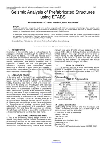
2. Nonlinear Demand Parameters and Model Attributesis not absolute. Nevertheless, the distinction provides apractical approach to establish requirements for the analysisand design. Deformation-controlled components must bemodeled as inelastic, whereas force-controlled componentsmay be modeled as elastic, provided that the force demandsdo not imply significant yielding in the components. ASCE41 defines deformation and strength acceptance criteria forImmediate Occupancy, Life Safety, and Collapse Preventionperformance levels, and PEER/ATC 72-1 provides guidanceon criteria for the onset of structural damage and significantstrength/stiffness degradation.2.1 Demand ParametersModern performance-based seismic design entails settingperformance levels and checking acceptance criteria forwhich a building is to be designed. Performance levels underdefined intensities of ground shaking should be checked usingappropriate demand parameters and acceptance criteria. Theperformance acceptance criteria may be specified for the overallsystems, substructures, or components of a building.For a given building and set of demand parameters, the structuremust be modeled and analyzed so that the values of the demandparameters are calculated with sufficient accuracy for designpurposes. The performance is checked by comparing thecalculated values of demand parameters (in short the “demands”)to the acceptance criteria (“capacities”) for the desiredperformance level. The calculated demands and acceptancecriteria are often compared through “demand-capacity” ratios.The acceptance criteria for seismic performance may varydepending on whether static or dynamic nonlinear analysis isused and how uncertainties associated with the demands andacceptance criteria are handled. For example, the componentmodels, demand parameters, and acceptance criteria used innonlinear static procedures need to implicitly account for cyclicdegradation effects that are not modeled in the static analysis.On the other hand, some dynamic analysis models may directlyincorporate degradation due to cyclic loading, in which casedifferent models and acceptance criteria may be used.Displacements, velocities, and accelerations are additionaldemand parameters that can provide insights into the overallbuilding response and damage to nonstructural componentsand contents. Story racking deformations (which can often beapproximated as story drift ratios) provide a good measure ofoverall structural response, including the vertical distribution ofdeformations and global torsion of the building, and demandsin deformation-sensitive components, such as the buildingfaçade, interior partitions, or flexible piping systems. Peakfloor accelerations and velocities are commonly used to designand assess performance of stiff acceleration-sensitive buildingcomponents, such as rigidly anchored equipment, raised floorsystems, braced ceiling systems, and rigid piping systems.2.2 Structural Analysis Model TypesInelastic structural component models can be differentiatedby the way that plasticity is distributed through the membercross sections and along its length. For example, shown inFigure 2-1 is a comparison of five idealized model types forsimulating the inelastic response of beam-columns. Severaltypes of structural members (e.g., beams, columns, braces,and some flexural walls) can be modeled using the conceptsillustrated in Figure 2-1:Acceptance criteria for structural components generallydistinguished between “deformation-controlled” (ductilecomponents that can tolerate inelastic deformations) and“force-controlled” (non-ductile components whose capacitiesare governed by strength). In reality, most components exhibitsome amount of inelastic deformation, and the distinctionbetween force- and deformation-controlled componentsFigure 2-1 – Idealized models of beam-column elements.Nonlinear Structural Analysis For Seismic Design: A Guide for Practicing Engineers4
The simplest models concentrate the inelastic deformationsat the end of the element, such as through a rigid-plastichinge (Figure 2-1a) or an inelastic spring with hystereticproperties (Figure 2-1b). By concentrating the plasticity inzero-length hinges with moment-rotation model parameters,these elements have relatively condensed numericallyefficient formulations.interpret relative to acceptance criteria that are typicallyreported in terms of hinge rotations and deformations.Concentrated and finite length hinge models (Figures 2-1athrough Figure 2-1c) may consider the axial force-moment(P-M) interactions through yield surfaces (see Figure 2-2). Onthe other hand, fiber (Figure 2-1d) and finite element (Figure2-1e) models capture the P-M response directly. Note thatwhile the detailed fiber and finite element models can simulatecertain behavior more fundamentally, they are not necessarilycapable of modeling other effects, such as degradation due toreinforcing bar buckling and fracture that can be captured bysimpler phenomenological models (Sidebar 3). The finite length hinge model (Figure 2-1c) is an efficientdistributed plasticity formulation with designated hingezones at the member ends. Cross sections in the inelastichinge zones are characterized through either nonlinearmoment-curvature relationships or explicit fiber-sectionintegrations that enforce the assumption that planesections remain plane. The inelastic hinge length maybe fixed or variable, as determined from the momentcurvature characteristics of the section together with theconcurrent moment gradient and axial force. Integrationof deformations along the hinge length captures the spreadof yielding more realistically than the concentrated hinges,while the finite hinge length facilitates calculation of hingerotations.Sidebar 3:Distributed Versus ConcentratedPlasticity ElementsWhile distributed plasticity formulations (Figures 2-1c to2-1e) model variations of the stress and strain throughthe section and along the member in more detail,important local behaviors, such as strength degradationdue to local buckling of steel reinforcing bars or flanges,or the nonlinear interaction of flexural and shear, aredifficult to capture without sophisticated and numericallyintensive models. On the other hand, phenomenologicalconcentrated hinge/spring models (Figure 2-1a and2-1b), may be better suited to capturing the nonlineardegrading response of members through calibrationusing member test data on phenomenological momentrotations and hysteresis curves. Thus, when selectinganalysis model types, it is important to understand (1)the expected behavior, (2) the assumptions, and (3) theapproximations inherent to the proposed model type.While more sophisticated formulations may seem tooffer better capabilities for modeling certain aspects ofbehavior, simplified models may capture more effectivelythe relevant feature with the same or lower approximation.It is best to gain knowledge and confidence in specificmodels and software implementations by analyzingsmall test examples, where one can interrogate specificbehavioral effects. The fiber formulation (Figure 2-1d) models distributeplasticity by numerical integrations through the membercross sections and along the member length. Uniaxialmaterial models are defined to capture the nonlinearhysteretic axial stress-strain characteristics in the crosssections. The plane-sections-remain-plane assumption isenforced, where uniaxial material “fibers” are numericallyintegrated over the cross section to obtain stress resultants(axial force and moments) and incremental momentcurvature and axial force-strain relations. The cross sectionparameters are then integrated numerically at discretesections along the member length, using displacement orforce interpolation functions (Kunnath et al. 1990, Spaconeet al. 1996). Distributed fiber formulations do not generallyreport plastic hinge rotations, but instead report strains in thesteel and concrete cross section fibers. The calculated straindemands can be quite sensitive to the moment gradient,element length, integration method, and strain hardeningparameters on the calculated strain demands. Therefore,the strain demands and acceptance criteria should bebenchmarked against concentrated hinge models, for whichrotation acceptance criteria are more widely reported.Some types of concentrated hinge models employ axial loadmoment (P-M) yiel
He has published two books and authored two computer platforms (IDARC and 3D-BASIS) for nonlinear analysis of structures and for base isolation systems. He has served as Director of the Structural Engineering and Earthquake Engineering Laboratory at the University at Buffalo. Michael R. Willf