Transcription
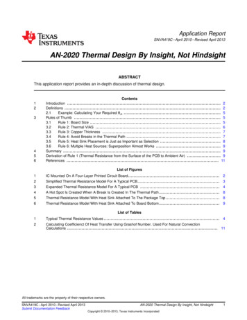
Technical NoteTN 166FTDI Example IC PCB FootprintsVersion 1.2Issue Date: 2019-06-14This Technical Note shows examples of FTDI IC PCB footprints which can beused as a guide for creating your own IC PCB footprints.Use of FTDI devices in life support and/or safety applications is entirely at the user’s risk, and theuser agrees to defend, indemnify and hold FTDI harmless from any and all damages, claims, suitsor expense resulting from such use.Future Technology Devices International Limited (FTDI)Unit 1, 2 Seaward Place, Glasgow G41 1HH, United KingdomTel.: 44 (0) 141 429 2777 Fax: 44 (0) 141 429 2758Web Site: http://ftdichip.comCopyright Future Technology Devices International Limited
Technical NoteTN 166 FTDI Example IC PCB FootprintsVersion 1.2Document Reference No.: FT 001321Clearance No.: FTDI# 501Table of Contents1 Introduction . 51.1 Scope .52 All Scaled Footprints . 62.1 DFN Packages.62.2 QFP Packages .62.3 QFN Packages.62.4 SSOP Packages .63 Packages by Product . 73.1 DFN Packages.73.2 QFP Packages .73.3 QFN Packages.73.4 SSOP Packages .74 10-pin DFN . 84.1 Scaled Footprint .84.2 Annotated Footprint .85 12-pin DFN . 95.1 Scaled Footprint .95.2 Annotated Footprint .96 16-pin QFN (4mm x 4mm) . 106.1 Scaled Footprint . 106.2 Annotated Footprint . 107 16-pin SSOP . 117.1 Scaled Footprint . 117.2 Annotated Footprint . 118 20-pin QFN . 128.1 Scaled Footprint . 128.2 Annotated Footprint . 12Product PageDocument Feedback1Copyright Future Technology Devices International Limited
Technical NoteTN 166 FTDI Example IC PCB FootprintsVersion 1.2Document Reference No.: FT 001321Clearance No.: FTDI# 5019 20-pin SSOP . 139.1 Scaled Footprint . 139.2 Annotated Footprint . 1310 24-pin QFN . 1410.1Scaled Footprint. 1410.2Annotated Footprint . 1411 24-pin SSOP . 1511.1Scaled Footprint. 1511.2Annotated Footprint . 1512 28-pin QFN . 1612.1Scaled Footprint. 1612.2Annotated Footprint . 1613 28-pin SSOP . 1713.1Scaled Footprint. 1713.2Annotated Footprint . 1714 28-pin TSSOP . 1814.1Scaled Footprint. 1814.2Annotated Footprint . 1815 28-pin WQFN . 1915.1Scaled Footprint. 1915.2Annotated Footprint . 1916 32-pin LQFP . 2016.1Scaled Footprint. 2016.2Annotated Footprint . 2017 32-pin VQFN/QFN (5mm x 5mm) . 2117.1Scaled Footprint. 2117.2Annotated Footprint . 2118 32-pin QFN (7mm x 7mm) . 22Product PageDocument Feedback2Copyright Future Technology Devices International Limited
Technical NoteTN 166 FTDI Example IC PCB FootprintsVersion 1.2Document Reference No.: FT 001321Clearance No.: FTDI# 50118.1Scaled Footprint. 2218.2Annotated Footprint . 2219 48-pin LQFP . 2319.1Scaled Footprint. 2319.2Annotated Footprint . 2320 48-pin QFN (8mm x 8mm) . 2420.1Scaled Footprint. 2420.2Annotated Footprint . 2421 56-pin QFN (7mm x 7mm) . 2521.1Scaled Footprint. 2521.2Annotated Footprint . 2522 56-pin VQFN (8mm x 8mm) . 2622.1Scaled Footprint. 2622.2Annotated Footprint . 2623 64-pin LQFP . 2723.1Scaled Footprint. 2723.2Annotated Footprint . 2724 64-pin TQFP . 2824.1Scaled Footprint. 2824.2Annotated Footprint . 2825 64-pin QFN (9mm x 9mm) . 2925.1Scaled Footprint. 2925.2Annotated Footprint . 2925.2.1Additional Information . 3026 76-pin QFN . 3126.1Scaled Footprint. 3126.2Annotated Footprint . 3127 Contact Information . 32Product PageDocument Feedback3Copyright Future Technology Devices International Limited
Technical NoteTN 166 FTDI Example IC PCB FootprintsVersion 1.2Document Reference No.: FT 001321Clearance No.: FTDI# 501Appendix A – References . 33Document References . 33Acronyms and Abbreviations. 33Appendix B – List of Tables & Figures . 34List of Tables.34List of Figures .34Appendix C – Revision History . 36Product PageDocument Feedback4Copyright Future Technology Devices International Limited
Technical NoteTN 166 FTDI Example IC PCB FootprintsVersion 1.2Document Reference No.: FT 001321Clearance No.: FTDI# 5011 IntroductionThis Technical Note shows examples of FTDI IC PCB footprints which can be used as a guide forcreating your own PCB footprints.The IC footprints in this document are sourced from various FTDI hardware such as developmentand application modules and demo hardware, using the most common and cost effective packagetypes.The IC footprints in this document provide: A 1:1 scaled IC footprintAn annotated IC footprint showing some key measurementsAll dimensions shown are in millimeters (mm).Additionally, a range of USB Interface IC solutions from FTDI Chip available through AltiumLive.To view Altium files, you need either the full version of ‘Altium Designer’, or ‘Altium Viewer’ whichcan be downloaded for free from Altium’s web Data.htmNote that all IC footprints may not be available through AltiumLive. Please contact FTDI in thiscase.1.1 ScopeThese IC PCB footprints can be used as a guide to create your own IC PCB footprints withparticular PCB design tools other than Altium.Please refer to the IC datasheet for full IC package parameters.Note: No guarantees can be provided in this document. These can be used as a guideonly.Note: FTDI Cables and Modules are recommended for product test and development prior tocustom hardware development.Product PageDocument Feedback5Copyright Future Technology Devices International Limited
Technical NoteTN 166 FTDI Example IC PCB FootprintsVersion 1.2Document Reference No.: FT 001321Clearance No.: FTDI# 5012 All Scaled FootprintsThis section shows all packages scaled to 1:1 size to show the exact package size which can helpwhen selecting a package to use in your design.Note that not all packages are available for all products. See Section 3 ‘Packages by Product’ inthis document, the product datasheet, or check the IC 1 DFN PackagesFigure 2.1 shown in pin count order from left to right:DFN-10, DFN-12.Figure 2.1 DFN Packages2.2 QFP PackagesFigure 2.2 shown in pin count order from left to right:LQFP-32, LQFP-48, LQFP-64, TQFP-64.Figure 2.2 QFP Packages2.3 QFN PackagesFigure 2.3 shown in pin count order from left to right:QFN-16 (4x4), QFN-20, QFN-24, QFN-28, WQFN-28, QFN-32 (5x5), QFN-32 (7x7), QFN-48 (8x8),QFN-56 (7x7), VQFN-56 (8x8), QFN-64 (9x9), QFN-76.Figure 2.3 QFN Packages2.4 SSOP PackagesFigure 2.4 shown in pin count order from left to right:SSOP-16, SSOP-20, SSOP-24, SSOP-28, TSSOP-28.Figure 2.4 SSOP PackagesProduct PageDocument Feedback6Copyright Future Technology Devices International Limited
Technical NoteTN 166 FTDI Example IC PCB FootprintsVersion 1.2Document Reference No.: FT 001321Clearance No.: FTDI# 5013 Packages by ProductPackage availability for FTDI products is shown in this section.3.1 DFN PackagesPackageDFN-10DFN-12Part NumbersFT200XDFT234XDTable 3.1 DFN Packages3.2 QFP PackagesPackageLQFP-32LQFP-48LQFP-64TQFP-64Part NumbersFT232BL, FT245BL, FT311D-32L1C,FT312D-32L1C, VNC2-32L1BFT232HL, FT2232D, VNC1L-1A, VNC2-48L1BFT2232HL, FT4232HL, FT313HLFT313HPTable 3.2 QFP Packages3.3 QFN PackagesPackageQFN-16 (4x4)QFN-20QFN-24QFN-28WQFN-28QFN-32 (5x5)QFN-32 (7x7)QFN-48 (8x8)QFN-56 (7x7)VQFN-56 (8x8)QFN-64 (9x9)QFN-76Part NumbersFT201XQ, FT220XQ, FT230XQFT221XQ, FT231XQFT240XQFT120QFT260QFT232RQ, FT245RQ, FT4222HQFT311D-32Q1C, FT312D-32Q1C,VNC2-32Q1BFT232HQ, VNC2-48Q1BFT600QFT2232H-56Q, FT4232H-56QFT2232HQ, FT4232HQ, FT313HQFT601Q, FT602QTable 3.3 QFN Packages3.4 SSOP 8Part NumbersFT201XS, FT220XS, FT230XSFT221XS, FT231XSFT240XSFT232RL, FT245RLFT120T, FT260STable 3.4 SSOP PackagesProduct PageDocument Feedback7Copyright Future Technology Devices International Limited
Technical NoteTN 166 FTDI Example IC PCB FootprintsVersion 1.2Document Reference No.: FT 001321Clearance No.: FTDI# 5014 10-pin DFNThe 10-pin DFN is used on the following product: FT200XDThis package is nominally 3.00mm x 3.00mm. The solder pads are on a 0.50mm pitch.Please see the IC Package Parameters in the IC datasheet for full information.4.1 Scaled FootprintThis 1:1 scaled footprint is the exact size when viewed or printed at 100%.Figure 4.1 10-pin DFN Scaled Footprint4.2 Annotated FootprintThe annotated footprint shows key measurements.Figure 4.2 10-pin DFN Annotated FootprintNote: Red top layer copper, other colors are mechanical layers.Note: Connect exposed center pad to GND. Do not place tracks on the top layer of the PCB in thisarea.Product PageDocument Feedback8Copyright Future Technology Devices International Limited
Technical NoteTN 166 FTDI Example IC PCB FootprintsVersion 1.2Document Reference No.: FT 001321Clearance No.: FTDI# 5015 12-pin DFNThe 12-pin DFN is used on the following product: FT234XDThis package is nominally 3.00mm x 3.00mm. The solder pads are on a 0.45mm pitch.Please see the IC Package Parameters in the IC datasheet for full information.5.1 Scaled FootprintThis 1:1 scaled footprint is the exact size when viewed or printed at 100%.Figure 5.1 12-pin DFN Scaled Footprint5.2 Annotated FootprintThe annotated footprint shows key measurements.Figure 5.2 12-pin DFN Annotated FootprintNote: Red top layer copper, other colors are mechanical layers.Note: Connect exposed center pad to GND. Do not place tracks on the top layer of the PCB in thisarea.Product PageDocument Feedback9Copyright Future Technology Devices International Limited
Technical NoteTN 166 FTDI Example IC PCB FootprintsVersion 1.2Document Reference No.: FT 001321Clearance No.: FTDI# 5016 16-pin QFN (4mm x 4mm)The 16-pin QFN (4mm x 4mm) is used on the following products: FT201XQFT220XQFT230XQThis package is nominally 4.00mm x 4.00mm. The solder pads are on a 0.65mm pitch.Please see the IC Package Parameters in the IC datasheet for full information.6.1 Scaled FootprintThis 1:1 scaled footprint is the exact size when viewed or printed at 100%.Figure 6.1 16-pin QFN (4mm x 4mm) Scaled Footprint6.2 Annotated FootprintThe annotated footprint shows key measurements.Figure 6.2 16-pin QFN (4mm x 4mm) Annotated FootprintNote: Red top layer copper, other colors are mechanical layers.Note: Connect exposed center pad to GND. Do not place tracks on the top layer of the PCB in thisarea.Product PageDocument Feedback10Copyright Future Technology Devices International Limited
Technical NoteTN 166 FTDI Example IC PCB FootprintsVersion 1.2Document Reference No.: FT 001321Clearance No.: FTDI# 5017 16-pin SSOPThe 16-pin SSOP is used on the following products: FT201XSFT220XSFT230XSThis package is nominally 4.90mm x 3.91mm body (4.90mm x 5.99mm including pins). The solderpads are on a 0.635mm pitch.Please see the IC Package Parameters in the IC datasheet for full information.7.1 Scaled FootprintThis 1:1 scaled footprint is the exact size when viewed or printed at 100%.Figure 7.1 16-pin SSOP Scaled Footprint7.2 Annotated FootprintThe annotated footprint shows key measurements.Figure 7.2 16-pin SSOP Annotated FootprintNote: Red top layer copper, other colors are mechanical layers.Product PageDocument Feedback11Copyright Future Technology Devices International Limited
Technical NoteTN 166 FTDI Example IC PCB FootprintsVersion 1.2Document Reference No.: FT 001321Clearance No.: FTDI# 5018 20-pin QFNThe 20-pin QFN is used on the following products: FT221XQFT231XQThis package is nominally 4.00mm x 4.00mm. The solder pads are on a 0.50mm pitch.Please see the IC Package Parameters in the IC datasheet for full information.8.1 Scaled FootprintThis 1:1 scaled footprint is the exact size when viewed or printed at 100%.Figure 8.1 20-pin QFN Scaled Footprint8.2 Annotated FootprintThe annotated footprint shows key measurements.Figure 8.2 20-pin QFN Annotated FootprintNote: Red top layer copper, other colors are mechanical layers.Note: Connect exposed center pad to GND. Do not place tracks on the top layer of the PCB in thisarea.Product PageDocument Feedback12Copyright Future Technology Devices International Limited
Technical NoteTN 166 FTDI Example IC PCB FootprintsVersion 1.2Document Reference No.: FT 001321Clearance No.: FTDI# 5019 20-pin SSOPThe 20-pin SSOP is used on the following products: FT221XSFT231XSThis package is nominally 8.66mm x 3.91mm body (8.66mm x 5.99mm including pins). The solderpads are on a 0.635mm pitch.Please see the IC Package Parameters in the IC datasheet for full information.9.1 Scaled FootprintThis 1:1 scaled footprint is the exact size when viewed or printed at 100%.Figure 9.1 20-pin SSOP Scaled Footprint9.2 Annotated FootprintThe annotated footprint shows key measurements.Figure 9.2 20-pin SSOP Annotated FootprintNote: Red top layer copper, other colors are mechanical layers.Product PageDocument Feedback13Copyright Future Technology Devices International Limited
Technical NoteTN 166 FTDI Example IC PCB FootprintsVersion 1.2Document Reference No.: FT 00132110Clearance No.: FTDI# 50124-pin QFNThe 24-pin QFN is used on the following product: FT240XQThis package is nominally 4.00mm x 4.00mm. The solder pads are on a 0.50mm pitch.Please see the IC Package Parameters in the IC datasheet for full information.10.1 Scaled FootprintThis 1:1 scaled footprint is the exact size when viewed or printed at 100%.Figure 10.1 24-pin QFN Scaled Footprint10.2 Annotated FootprintThe annotated footprint shows key measurements.Figure 10.2 24-pin QFN Annotated FootprintNote: Red top layer copper, other colors are mechanical layers.Note: Connect exposed center pad to GND. Do not place tracks on the top layer of the PCB in thisarea.Product PageDocument Feedback14Copyright Future Technology Devices International Limited
Technical NoteTN 166 FTDI Example IC PCB FootprintsVersion 1.2Document Reference No.: FT 00132111Clearance No.: FTDI# 50124-pin SSOPThe 24-pin SSOP is used on the following products: FT240XSThis package is nominally 8.66mm x 3.91 mm body (8.66mm x 5.99mm including pins). Thesolder pads are on a 0.635mm pitch.Please see the IC Package Parameters in the IC datasheet for full information.11.1 Scaled FootprintThis 1:1 scaled footprint is the exact size when viewed or printed at 100%.Figure 11.1 24-pin SSOP Scaled Footprint11.2 Annotated FootprintThe annotated footprint shows key measurements.Figure 11.2 24-pin SSOP Annotated FootprintNote: Red top layer copper, other colors are mechanical layers.Product PageDocument Feedback15Copyright Future Technology Devices International Limited
Technical NoteTN 166 FTDI Example IC PCB FootprintsVersion 1.2Document Reference No.: FT 00132112Clearance No.: FTDI# 50128-pin QFNThe 28-pin QFN is used on the following products: FT120QThis package is nominally 4.00mm x 4.00mm. The solder pads are on a 0.40mm pitch.Please see the IC Package Parameters in the IC datasheet for full information.12.1 Scaled FootprintThis 1:1 scaled footprint is the exact size when viewed or printed at 100%.Figure 12.1 28-pin QFN Scaled Footprint12.2 Annotated FootprintThe annotated footprint shows key measurements.Figure 12.2 28-pin QFN Annotated FootprintNote: Red top layer copper, other colors are mechanical layers.Note: Connect exposed center pad to GND. Do not place tracks on the top layer of the PCB in thisarea.Product PageDocument Feedback16Copyright Future Technology Devices International Limited
Technical NoteTN 166 FTDI Example IC PCB FootprintsVersion 1.2Document Reference No.: FT 00132113Clearance No.: FTDI# 50128-pin SSOPThe 28-pin SSOP is used on the following products: FT232RLFT245RLThis package is nominally 5.30mm x 10.20mm body (7.80mm x 10.20mm including pins). Thesolder pads are on a 0.65mm pitch.Please see the IC Package Parameters in the IC datasheet for full information.13.1 Scaled FootprintThis 1:1 scaled footprint is the exact size when viewed or printed at 100%.Figure 13.1 28-pin SSOP Scaled Footprint13.2 Annotated FootprintThe annotated footprint shows key measurements.Figure 13.2 28-pin SSOP Annotated FootprintNote: Red top layer copper, other colors are mechanical layersProduct PageDocument Feedback17Copyright Future Technology Devices International Limited
Technical NoteTN 166 FTDI Example IC PCB FootprintsVersion 1.2Document Reference No.: FT 00132114Clearance No.: FTDI# 50128-pin TSSOPThe 28-pin TSSOP is used on the following products: FT120TFT260SThis package is nominally 9.7mm x 4.4mm body (9.7mm x 6.4mm including pins). The solderpads are on a 0.65mm pitch.Please see the IC Package Parameters in the IC datasheet for full information.14.1 Scaled FootprintThis 1:1 scaled footprint is the exact size when viewed or printed at 100%.Figure 14.1 28-pin TSSOP Scaled Footprint14.2 Annotated FootprintThe annotated footprint shows key measurements.Figure 14.2 28-pin TSSOP Annotated FootprintNote: Red top layer copper, other colors are mechanical layers.Product PageDocument Feedback18Copyright Future Technology Devices International Limited
Technical NoteTN 166 FTDI Example IC PCB FootprintsVersion 1.2Document Reference No.: FT 00132115Clearance No.: FTDI# 50128-pin WQFNThe 28-pin WQFN is used on the following product: FT260QThis package is nominally 5.00mm x 5.00mm. The solder pads are on a 0.50mm pitch.Please see the IC Package Parameters in the IC datasheet for full information.15.1 Scaled FootprintThis 1:1 scaled footprint is the exact size when viewed or printed at 100%.Figure 15.1 28-pin WQFN Scaled Footprint15.2 Annotated FootprintThe annotated footprint shows key measurements.Figure 15.2 28-pin WQFN Annotated FootprintNote: Red top layer copper, other colors are mechanical layers.Note: Connect exposed center pad to GND. Do not place tracks on the top layer of the PCB in thisarea.Product PageDocument Feedback19Copyright Future Technology Devices International Limited
Technical NoteTN 166 FTDI Example IC PCB FootprintsVersion 1.2Document Reference No.: FT 00132116Clearance No.: FTDI# 50132-pin LQFPThe 32-pin LQFP is used on the following products: is package is nominally 9.00mm x 9.00mm. The solder pads are on a 0.80mm pitch.Please see the IC Package Parameters in the IC datasheet for full information.16.1 Scaled FootprintThis 1:1 scaled footprint is the exact size when viewed or printed at 100%.Figure 16.1 32-pin LQFP Scaled Footprint16.2 Annotated FootprintThe annotated footprint shows key measurements.Figure 16.2 32-pin LQFP Annotated FootprintNote: Red top layer copper, other colors are mechanical layers.Product PageDocument Feedback20Copyright Future Technology Devices International Limited
Technical NoteTN 166 FTDI Example IC PCB FootprintsVersion 1.2Document Reference No.: FT 00132117Clearance No.: FTDI# 50132-pin VQFN/QFN (5mm x 5mm)The 32-pin VQFN/QFN (5mm x 5mm) is used on the following products: FT232RQFT245RQFT4222HQThis package is nominally 5.00mm x 5.00mm. The solder pads are on a 0.50mm pitch.Please see the IC Package Parameters in the IC datasheet for full information.17.1 Scaled FootprintThis 1:1 scaled footprint is the exact size when viewed or printed at 100%.Figure 17.1 32-pin VQFN/QFN (5mm x 5mm) Scaled Footprint17.2 Annotated FootprintThe annotated footprint shows key measurements.Figure 17.2 32-pin VQFN/QFN (5mm x 5mm) Annotated FootprintNote: Red top layer copper, other colors are mechanical layers.Note: Connect exposed center pad to GND. Do not place tracks on the top layer of the PCB in thisarea.Product PageDocument Feedback21Copyright Future Technology Devices International Limited
Technical NoteTN 166 FTDI Example IC PCB FootprintsVersion 1.2Document Reference No.: FT 00132118Clearance No.: FTDI# 50132-pin QFN (7mm x 7mm)The 32-pin QFN (7mm x 7mm) is used on the following products: VNC2-32Q1BFT311D-32Q1CFT312D-32Q1CThis package is nominally 7.00mm x 7.00mm. The solder pads are on a 0.65mm pitch.Please see the IC Package Parameters in the IC datasheet for full information.18.1 Scaled FootprintThis 1:1 scaled footprint is the exact size when viewed or printed at 100%.Figure 18.1 32-pin QFN (7mm x 7mm) Scaled Footprint18.2 Annotated FootprintThe annotated footprint shows key measurements.Figure 18.2 32-pin QFN (7mm x 7mm) Annotated FootprintNote: Red top layer copper, other colors are mechanical layers.Note: Connect exposed center pad to GND. Do not place tracks on the top layer of the PCB in thisarea.Product PageDocument Feedback22Copyright Future Technology Devices International Limited
Technical NoteTN 166 FTDI Example IC PCB FootprintsVersion 1.2Document Reference No.: FT 00132119Clearance No.: FTDI# 50148-pin LQFPThe 48-pin LQFP is used on the following products: FT232HLFT2232DVNC1L-1AVNC2-48Q1BThis package is nominally 9.00mm x 9.00mm. The solder pads are on a 0.50mm pitch.Please see the IC Package Parameters in the IC datasheet for full information.19.1 Scaled FootprintThis 1:1 scaled footprint is the exact size when viewed or printed at 100%.Figure 19.1 48-pin LQFP Scaled Footprint19.2 Annotated FootprintThe annotated footprint shows key measurements.Figure 19.2 48-pin LQFP Annotated FootprintNote: Red top layer copper, other colors are mechanical layers.Product PageDocument Feedback23Copyright Future Technology Devices International Limited
Technical NoteTN 166 FTDI Example IC PCB FootprintsVersion 1.2Document Reference No.: FT 00132120Clearance No.: FTDI# 50148-pin QFN (8mm x 8mm)The 48-pin QFN (8mm x 8mm) is used on the following products: VNC2-48Q1BFT232HQThis package is nominally 8.00mm x 8.00mm. The solder pads are on a 0.50mm pitch.Please see the IC Package Parameters in the IC datasheet for full information.20.1 Scaled FootprintThis 1:1 scaled footprint is the exact size when viewed or printed at 100%.Figure 20.1 48-pin QFN (8mm x 8mm) Scaled Footprint20.2 Annotated FootprintThe annotated footprint shows key measurements.Figure 20.2 48-pin QFN (8mm x 8mm) Annotated FootprintNote: Red top layer copper, other colors are mechanical layers.Note: Connect exposed center pad to GND. Do not place tracks on the top layer of the PCB in thisarea.Product PageDocument Feedback24Copyright Future Technology Devices International Limited
Technical NoteTN 166 FTDI Example IC PCB FootprintsVersion 1.2Document Reference No.: FT 00132121Clearance No.: FTDI# 50156-pin QFN (7mm x 7mm)The 56-pin QFN (7mm x 7mm) is used on the following product: FT600QThis package is nominally 7.00mm x 7.00mm. The solder pads are on a 0.40mm pitch.Please see the IC Package Parameters in the IC datasheet for full information.21.1 Scaled FootprintThis 1:1 scaled footprint is the exact size when viewed or printed at 100%.Figure 21.1 56-pin QFN (7mm x 7mm) Scaled Footprint21.2 Annotated FootprintThe annotated footprint shows key measurements.Figure 21.2 56-pin QFN (7mm x 7mm) Annotated FootprintNote: Red top layer copper, other colors are mechanical layers.Note: Connect exposed center pad to GND. Do not place tracks on the top layer of the PCB in thisarea. Cross-hatching designs used for less solder paste and less heat up rate required.Product PageDocument Feedback25Copyright Future Technology Devices International Limited
Technical NoteTN 166 FTDI Example IC PCB FootprintsVersion 1.2Document Reference No.: FT 00132122Clearance No.: FTDI# 50156-pin VQFN (8mm x 8mm)The 56-pin VQFN (8mm x 8mm) is used on the following products: FT2232H-56QFT4232H-56QThis package is nominally 8.00mm x 8.00mm. The solder pads are on a 0.50mm pitch.Please see the IC Package Parameters in the IC datasheet for full information.22.1 Scaled FootprintThis 1:1 scaled footprint is the exact size when viewed or printed at 100%.Figure 22.1 56-pin VQFN (8mm x 8mm) Scaled Footprint22.2 Annotated FootprintThe annotated footprint shows key measurements.Figure 22.2 56-pin VQFN (8mm x 8mm) Annotated FootprintNote: Red top layer copper, other colors are mechanical layers.Note: Connect exposed center pad to GND. Do not place tracks on the top layer of the PCB in thisarea.Product PageDocument Feedback26Copyright Future Technology Devices International Limited
Technical NoteTN 166 FTDI Example IC PCB FootprintsVersion 1.2Document Reference No.: FT 00132123Clearance No.: FTDI# 50164-pin LQFPThe 64-pin LQFP is used on the following products: FT313HLFT2232HLFT4232HLThis package is nominally 12.00mm x 12.00mm. The solder pads are on a 0.50mm pitch.Please see the IC Package Parameters in the IC datasheet for full information.23.1 Scaled FootprintThis 1:1 scaled footprint is the exact size when viewed or printed at 100%.Figure 23.1 64-pin LQFP Scaled Footprint23.2 Annotated FootprintThe annotated footprint shows key measurements.Figure 23.2 64-pin LQFP Annotated FootprintNote: Red top layer copper, other colors are mechanical layers.Product PageDocument Feedback27Copyright Future Technology Devices International Limited
Technical NoteTN 166 FTDI Example IC PCB FootprintsVersion 1.2Document Refere
Use of FTDI devices in life support and/or safety applications is entirely at the user’s risk, and the user agrees to defend, indemnify and hold FTDI harmless from any and all damages, claims, suits . you need either the full version of ‘Altium Designer’, or ‘Altium Viewer’ which can be dow