Transcription
Application ReportSLVA670A – August 2014 – Revised May 2015Managing Inrush CurrentAlek Kaknevicius and Adam Hoover. Drivers and Load SwitchesABSTRACTIn most systems, capacitors are placed throughout a design to ensure there are no voltage drops on thesupply rails. When power is initially applied to the system, charging these capacitors can result in aninrush current which can exceed the nominal load current. If left unaddressed, this can cause voltage railsto fall out of regulation, resulting in the system entering an undesired state. Additionally, the inrush currentcan exceed the current carrying capability of board connectors as well as PCB traces, resulting indamaging the connectors and traces.These problems can be mitigated by using Texas Instruments load switches. The load switches in theTPS229xx family are slew rate controlled to minimize inrush current. This application note explores typicalcauses of inrush current, problems caused by inrush current, and solutions for inrush current featuringintegrated load switches.123456ContentsWhat is Inrush Current? . 21.1Effects of Load Capacitance . 3Problems Caused by Inrush Current . 4Methods of Reducing Inrush Current. 53.1"Soft-start” or Voltage Regulators . 53.2Discrete Implementation . 53.3Integrated Load Switches . 63.4Advantages and Disadvantages of these Solutions . 6Application Examples . 74.1Effects of Using a Slew Rate Controlled Load Switch . 10Conclusion . 12References . 12SLVA670A – August 2014 – Revised May 2015Submit Documentation FeedbackCopyright 2014–2015, Texas Instruments IncorporatedManaging Inrush Current1
What is Inrush Current?1www.ti.comWhat is Inrush Current?An example system, shown in Figure 1, uses a power supply – DC/DC, LDO, or external supply – tosupply voltage to a downstream load.LoadPower SupplyLoadLoadFigure 1. Typical Power DistributionUpon system startup, the power supply will ramp up to the regulated voltage. As the voltage increases,an inrush of current flows into the uncharged capacitors. Inrush current can also be generated when acapacitive load is switched onto a power rail and must be charged to that voltage level. The amount ofinrush current into the capacitors is determined by the slope of the voltage ramp as described inEquation 1:dVIINRUSH CLOAD dt(1)WhereIINRUSH amount of inrush current caused by a capacitanceC total capacitancedV change in voltage during ramp updt rise time (during voltage ramp up)2Managing Inrush CurrentSLVA670A – August 2014 – Revised May 2015Submit Documentation FeedbackCopyright 2014–2015, Texas Instruments Incorporated
What is Inrush Current?www.ti.com1.1Effects of Load CapacitanceIncreasing the system capacitance to reduce transient voltage dips comes at the cost of increased inrushcurrent generated from charging the increased capacitance. The following two figures display inrushcurrent by showing a power supply starting up into different capacitive loads. Figure 2, below, shows ascope shot of a 3.3 V power supply starting up into a 47 µF capacitance.Figure 2. 3.3V Applied to a 47µF CapacitorIn Figure 2, as the power supply turns on and the capacitor charges, over 3.12 A of inrush current isgenerated. Figure 3, below, shows the same power supply turning on with a lower capacitance.Figure 3. 3.3 V Applied to a 22 µF CapacitorWith a reduced capacitance of 22 µF, Figure 3 shows that the inrush current is reduced to 1.6 A.Reducing the load capacitance decreases inrush current, but it can also decrease voltage rail stabilityduring transient current events. Certain loads may require specific output capacitance to operate, andreducing this output capacitance is not an option. Solutions to this scenario are discussed in Section 3.SLVA670A – August 2014 – Revised May 2015Submit Documentation FeedbackCopyright 2014–2015, Texas Instruments IncorporatedManaging Inrush Current3
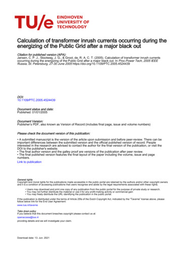
Problems Caused by Inrush Current2www.ti.comProblems Caused by Inrush CurrentThere are two key concerns associated with inrush current. The first is exceeding the absolute maximumcurrent ratings of the traces and components on a PCB. All connectors and terminal blocks have a specificcurrent rating which, if exceeded, could cause damage to these parts. Likewise, all PCB traces aredesigned with a certain current carrying capability in mind and are also at risk to damage. When designingthe PCB traces and selecting connectors, not taking the inrush current peak into account can damage thepower path and lead to system failure; however, appropriately designing for a large inrush current peakwill lead to thicker PCB traces and more durable connectors which can increase the size and cost of theoverall design.The second problem occurs when a capacitive load switches onto an already stable voltage rail. If thepower supply cannot handle the amount of inrush current needed to charge that capacitor, then thevoltage on that rail will be pulled down. Figure 4 is an example of a 100 µF capacitance being applied to avoltage supply without any slew rate control. The capacitance generates 6.88 A of inrush current andforces the voltage rail to drop from 3.3 V down to 960 mV.Figure 4. Power Supply Dip due to Inrush CurrentIf other modules are connected to this power rail and the voltage drops, then these modules may resetthemselves and put the rest of the system into an undesired state. If the voltage regulator is unable tosupply enough current at turn-on, the voltage rail could collapse completely leading to system failure.4Managing Inrush CurrentSLVA670A – August 2014 – Revised May 2015Submit Documentation FeedbackCopyright 2014–2015, Texas Instruments Incorporated
Methods of Reducing Inrush Currentwww.ti.com3Methods of Reducing Inrush CurrentInrush current can be reduced by increasing the voltage rise time on the load capacitance and slowingdown the rate at which the capacitors charge. Three different solutions to reduce inrush current are shownbelow: voltage regulators, discrete components, and integrated load switches. All three of these solutionscenter around increasing the voltage rise time which, as shown in Equation 1, leads to reduced inrushcurrent.3.1"Soft-start” or Voltage RegulatorsVoltage regulators, DC/DC converters, and LDOs may have an integrated soft-start functionality. With thisfeature, the rise time can be increased, thereby reducing the inrush current. With a properly selectedDC/DC converter or LDO, the inrush can be effectively managed to ensure system stability.3.2Discrete ImplementationPower switching with a controlled rise time can be accomplished by using discrete circuitry and can bedone in several ways. An example circuit of one solution is shown in Figure 5. This particular solutionrequires a minimum of 4 components (2 MOSFETS, 2 resistors) and the slew rate of VOUT can becontrolled by using the resistor RSR. However, RSR needs to be very large (in the range of MΩ) to have aneffect on the rise time of VOUT. To be able to reduce the value of RSR, an additional capacitor would needto be added.Figure 5. Discrete Load Switch ImplementationSLVA670A – August 2014 – Revised May 2015Submit Documentation FeedbackCopyright 2014–2015, Texas Instruments IncorporatedManaging Inrush Current5
Methods of Reducing Inrush Current3.3www.ti.comIntegrated Load SwitchesIntegrated load switches can be used in place of the discrete solution discussed in Section 3.2. All TexasInstruments load switches (TPS229xx products) feature a controlled output slew rate to mitigate inrushcurrent. Figure 6 below shows the typical application circuit for a load switch.Figure 6. Typical Load Switch Application Circuit3.4Advantages and Disadvantages of these SolutionsWhile all of these solutions can help to manage inrush current, they all come with their advantages anddisadvantages. The least integrated of all the above solutions is the discrete implementation. Whencompared to its integrated counterpart, the load switch, it requires more components and a much largersolution size. By contrast, the most integrated solution is the DC/DC converter or voltage regulator withsoft-start already built in. Despite its integration, adding load switches may be more beneficial for thesystem. If a voltage rail requires multiple capacitive loads which need to be switched individually, thenmultiple load switches can be used rather than multiple voltage regulators. This will reduce overall costand solution size. Also, if the chosen voltage regulator does not come with an integrated slew rate control,then a load switch can be used before or after to provide that function. Adding a load switch to a systemfor inrush current control may require an additional component, but it can reduce the overall design sizeand cost.6Managing Inrush CurrentSLVA670A – August 2014 – Revised May 2015Submit Documentation FeedbackCopyright 2014–2015, Texas Instruments Incorporated
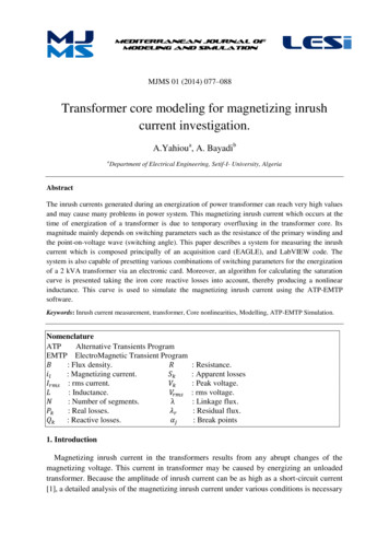
Application Exampleswww.ti.com4Application ExamplesThe following application examples will use the design parameters shown in Table 1:Table 1. Application Example 1Design ParameterExample ValueLoad Switch input voltage (VIN)3.3 VCapacitive load (CLOAD)22 µFMaximum acceptable inrush current600 mAUsing a VIN of 3.3 V, a CLOAD of 22 µF, and a maximum acceptable inrush current of 600 mA, the requiredrise time for the output can be calculated.Starting with Equation 2,dVIINRUSH CLOAD dt(2)The rise time can be calculated as:C dV 22 µF 3.3 Vdt LOAD 121 µsIINRUSH600 mA(3)This means that the load switch which is chosen for this application must have a rise time of 121µs orhigher. By visiting www.ti.com/loadswitches, all available Texas Instruments load switches can be sortedby rise time using the online parametric table. Using this method, an appropriate load switch can bechosen.4.0.1Fixed Rise Time SolutionAt VIN 3.3 V, the TPS22902B has a typical rise time of 146 µs and can be used to ensure an inrushcurrent lower than 600 mA. The controlled rise time of the load switch and resulting inrush current areshown in Figure 7.Figure 7. TPS22902B Inrush CurrentThe peak inrush current measured is 392 mA. This is well below the 600 mA design requirement andmuch lower than the 1.6 A seen in Figure 3 without any load switches being used. By selecting thecorrect load switch, the inrush current is effectively managed.SLVA670A – August 2014 – Revised May 2015Submit Documentation FeedbackCopyright 2014–2015, Texas Instruments IncorporatedManaging Inrush Current7
Application Exampleswww.ti.comSeveral Texas Instruments load switches with a fixed rise time have A, B, C, or D variations. These lettersare used at the end of the part number to denote different rise times. An A version load switch has thefastest rise time (typically below 10 µs) and a D version load switch has the slowest (several milliseconds).For example, the TPS22924 load switch has B, C, and D variations with rise times of 96 µs, 800 µs, and9 ms, respectively. In this application example, a rise time of greater than 121 µs was calculated to limitthe inrush current to 600 mA. The rise time of the B version would be too fast and either the C or Dversion could be used.4.0.2Adjustable Rise Time SolutionAll Texas Instruments load switches feature a controlled rise time, and for some load switches this risetime can be adjusted. The rise time of these devices can be increased by adding an external capacitorbetween the available CT pin and GND. The TPS22965 offers this feature, and its typical applicationschematic shown in Figure 8.CINVINVOUTONCTCLONOFFVBIASGNDTPS22965Figure 8. TPS22965 Application CircuitUsing the datasheet for this device, the appropriate CT capacitor can be chosen to implement a desiredrise time. Both the equation and table in the Adjustable Rise Time section of the TPS22965 datasheetcan be used to this effect. Figure 9 below shows the datasheet table which allows the user to determinethe appropriate CT capacitor needed for a desired rise time.Figure 9. TPS22965 Rise Time vs CT Capacitor8Managing Inrush CurrentSLVA670A – August 2014 – Revised May 2015Submit Documentation FeedbackCopyright 2014–2015, Texas Instruments Incorporated
Application Exampleswww.ti.comIf no CT capacitor is used, then the rise time of the load switch may be too fast to limit the inrush currentto the desired peak value. Figure 10 shows the TPS22965 powering up into a 22 µF load without any CTcapacitance.Figure 10. TPS22965 Scope Capture (CT cap 0 pF)With no CT capacitor, the rise time of the TPS22965 is faster than the calculated 121 µs and results in aninrush current of about 670 mA, larger than the design goal of 600 mA. The below screenshots show thedevice powering up into the 22 µF load with different CT capacitors.Figure 11. TPS22965 Scope Capture (CT cap 150 pF)SLVA670A – August 2014 – Revised May 2015Submit Documentation FeedbackCopyright 2014–2015, Texas Instruments IncorporatedManaging Inrush Current9
Application Exampleswww.ti.comFigure 12. TPS22965 Scope Capture (CT cap 2200 pF)Figure 11 was taken with a CT capacitor of 150 pF and Figure 12 with 2200 pF. As the CT capacitorincreases, the rise time of the device also increases and the inrush current is reduced to well below thedesign goal of 600 mA. While the CT pin increases the amount of flexibility in design, it does require anadditional component to implement. However, this allows for a single load switch to be used acrossmultiple designs with varying capacitive loads.4.1Effects of Using a Slew Rate Controlled Load SwitchThe following example uses a 5 V power supply which is brought down to 1.8 V using a buck converter.After the 1.8 V rail has powered up, a 100 µF capacitance is applied to the system, as shown in Figure 13.4.1.1Response without Slew Rate Control5V PowerSupply1.8V BuckConverterVOUT66µF100µFINRUSHFigure 13. System Block Diagram without Slew Rate Control10Managing Inrush CurrentSLVA670A – August 2014 – Revised May 2015Submit Documentation FeedbackCopyright 2014–2015, Texas Instruments Incorporated
Application Exampleswww.ti.comWith no controlled rise time, the switch does not provide any inrush current management and the followingresults can be observed:Figure 14. Inrush Current and Voltage Drop without Slew Rate ControlThe inrush current generated by the 100 µF capacitor peaks at 6.46 A and brings the 1.8 V rail down to320 mV. This 82% voltage reduction on the power rail can cause the system to reset or fail.4.1.2Response with Slew Rate Control from a Load SwitchFigure 15 shows the same system as before, except the TPS22965 load switch from Texas Instrumentswith controlled rise time is used to switch the 100 µF capacitive load.5V PowerSupply1.8V ure 15. System Block Diagram utilizing the TPS22965SLVA670A – August 2014 – Revised May 2015Submit Documentation FeedbackCopyright 2014–2015, Texas Instruments IncorporatedManaging Inrush Current11
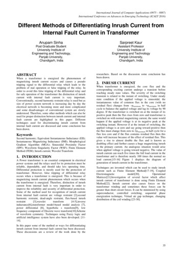
Conclusionwww.ti.comUsing a 150 pF capacitor on the CT pin of the load switch, the following results can be observed:Figure 16. Inrush Current and Voltage Drop with Slew Rate ControlWith the controlled slew rate of the TPS22965, the maximum inrush current drops from 6.46 A to 960 mA.The 1.8 V output of the buck converter also shows no significant voltage drop.5ConclusionLarge capacitance can lead to inrush current resulting in device damage, system instability or undesiredbehavior. Using a TI load switch is a size and cost efficient solution for managing inrush current.The TI load switch portfolio has a wide variety of parts with different slew rates to address the inrushcurrents of different system requirements. By using Equation 1 and the parametric search table atti.com/loadswitches, inrush current can be effectively managed by using a TI Integrated Load Switch fromthe TPS229xx family.6References1. TPS22965, 5.7-V, 6-A, 16-mΩ On-Resistance Load Switch (SLVSBJ0)2. TPS22902B, 3.6-V, 500-mA, 78-mΩ ON-Resistance Load Switch With Controlled Turnon (SLVS803)12Managing Inrush CurrentSLVA670A – August 2014 – Revised May 2015Submit Documentation FeedbackCopyright 2014–2015, Texas Instruments Incorporated
IMPORTANT NOTICETexas Instruments Incorporated and its subsidiaries (TI) reserve the right to make corrections, enhancements, improvements and otherchanges to its semiconductor products and services per JESD46, latest issue, and to discontinue any product or service per JESD48, latestissue. Buyers should obtain the latest relevant information before placing orders and should verify that such information is current andcomplete. All semiconductor products (also referred to herein as “components”) are sold subject to TI’s terms and conditions of salesupplied at the time of order acknowledgment.TI warrants performance of its components to the specifications applicable at the time of sale, in accordance with the warranty in TI’s termsand conditions of sale of semiconductor products. Testing and other quality control techniques are used to the extent TI deems necessaryto support this warranty. Except where mandated by applicable law, testing of all parameters of each component is not necessarilyperformed.TI assumes no liability for applications assistance or the design of Buyers’ products. Buyers are responsible for their products andapplications using TI components. To minimize the risks associated with Buyers’ products and applications, Buyers should provideadequate design and operating safeguards.TI does not warrant or represent that any license, either express or implied, is granted under any patent right, copyright, mask work right, orother intellectual property right relating to any combination, machine, or process in which TI components or services are used. Informationpublished by TI regarding third-party products or services does not constitute a license to use such products or services or a warranty orendorsement thereof. Use of such information may require a license from a third party under the patents or other intellectual property of thethird party, or a license from TI under the patents or other intellectual property of TI.Reproduction of significant portions of TI information in TI data books or data sheets is permissible only if reproduction is without alterationand is accompanied by all associated warranties, conditions, limitations, and notices. TI is not responsible or liable for such altereddocumentation. Information of third parties may be subject to additional restrictions.Resale of TI components or services with statements different from or beyond the parameters stated by TI for that component or servicevoids all express and any implied warranties for the associated TI component or service and is an unfair and deceptive business practice.TI is not responsible or liable for any such statements.Buyer acknowledges and agrees that it is solely responsible for compliance with all legal, regulatory and safety-related requirementsconcerning its products, and any use of TI components in its applications, notwithstanding any applications-related information or supportthat may be provided by TI. Buyer represents and agrees that it has all the necessary expertise to create and implement safeguards whichanticipate dangerous consequences of failures, monitor failures and their consequences, lessen the likelihood of failures that might causeharm and take appropriate remedial actions. Buyer will fully indemnify TI and its representatives against any damages arising out of the useof any TI components in safety-critical applications.In some cases, TI components may be promoted specifically to facilitate safety-related applications. With such components, TI’s goal is tohelp enable customers to design and create their own end-product solutions that meet applicable functional safety standards andrequirements. Nonetheless, such components are subject to these terms.No TI components are authorized for use in FDA Class III (or similar life-critical medical equipment) unless authorized officers of the partieshave executed a special agreement specifically governing such use.Only those TI components which TI has specifically designated as military grade or “enhanced plastic” are designed and intended for use inmilitary/aerospace applications or environments. Buyer acknowledges and agrees that any military or aerospace use of TI componentswhich have not been so designated is solely at the Buyer's risk, and that Buyer is solely responsible for compliance with all legal andregulatory requirements in connection with such use.TI has specifically designated certain components as meeting ISO/TS16949 requirements, mainly for automotive use. In any case of use ofnon-designated products, TI will not be responsible for any failure to meet dioAutomotive and fier.ti.comCommunications and Telecomwww.ti.com/communicationsData Convertersdataconverter.ti.comComputers and Peripheralswww.ti.com/computersDLP Productswww.dlp.comConsumer ergy and Lightingwww.ti.com/energyClocks and wer Mgmtpower.ti.comSpace, Avionics and ollersmicrocontroller.ti.comVideo and Imagingwww.ti.com/videoRFIDwww.ti-rfid.comOMAP Applications Processorswww.ti.com/omapTI E2E Communitye2e.ti.comWireless Connectivitywww.ti.com/wirelessconnectivityMailing Address: Texas Instruments, Post Office Box 655303, Dallas, Texas 75265Copyright 2015, Texas Instruments Incorporated
TPS22902B Inrush Current The peak inrush current measured is 392 mA. This is well below the 600 mA design requirement and much lower than the 1.6 A seen in Figure 3 without any load switches being used. By selecting the correct load switch, the inrush current is effectively managed.