Transcription
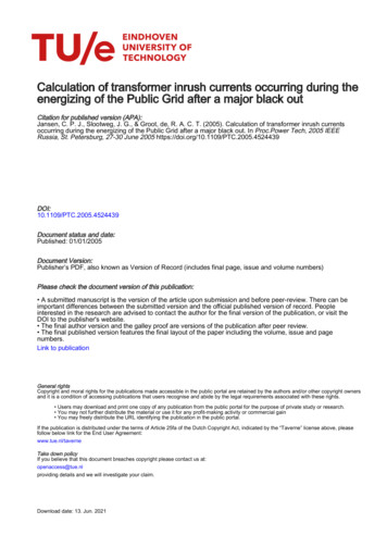
International Journal of Computer Applications (0975 – 8887)International Conference on Advances in Emerging Technology (ICAET 2016)Different Methods of Differentiating Inrush Current fromInternal Fault Current in TransformerAnupam SinhaSarpreet KaurPost Graduate StudentUniversity Institute ofEngineering and Technology,Panjab University,Chandigarh, IndiaAssistant ProfessorUniversity Institute ofEngineering and TechnologyPanjab University,Chandigarh, IndiaABSTRACTWhen a transformer is energized the phenomenon ofmagnetizing inrush current occurs and causes a pseudotripping signal to the differential relay which leads to theproblem of mal operation or false tripping of the relay. Inorder to avoid this false tripping of the differential relay andfor safe operation of the transformer the distinction of inrushcurrent with internal fault current is very important.Conventionally, second harmonic restraint relay is used but assize of power system network is increasing day by day theelectrical network is becoming more and more complicatedand some disadvantages of conventional system are slowlyunderstood. Therefore, some other methods which can also beused for proper distinction between inrush current and internalfault current are highlighted in this paper. Differenttechniques used for discriminating inrush current frominternal fault current are discussed and some conclusion hasbeen drawn.KeywordsSecond harmonic; Equivalent Instantaneous Inductance (EII);Instantaneous Magnetizing Inductance (IMI); MorphologicalGradient Algorithm (MGA); Sinusoidal Proximity Factor(SPF); Waveform Singularity Factor (WSF); Finite ElementMethod (FEM); Inrush current; Wavelet Transform1. INTRODUCTIONA Power transformer is an essential component in electricalpower systems and the relays used for its protection must bereliable, dependable, and should take less operating time.Differential protection is mostly used for the protection oftransformer. However, false tripping of differential relayoccurs when a transformer is energized. This is because ofmagnetizing inrush current phenomenon which occurs whenthe transformer is energized. Therefore, distinction of inrushcurrent from internal fault is very important in order toimprove the reliability and security of differential protection.Some of the method used for recognition of inrush currentfrom internal fault current are voltage restraint [2],secondharmonic restraint, dead-angle restraint, flux-based ductance[6],transformer model-based modal analysis [7],power differential [8], hyperbolic s transform[9], lowfrequency component of Discrete wave transform[10],Schemeof waveform symmetry. Techniques using Fuzzy logic andartificial intelligence system have also been developed. [1114].researchers. Based on the discussion some conclusion hasbeen drawn.2. INRUSH CURRENTWhen transformer is energized, the core flux and thecorresponding exciting current undergo a transient beforereaching steady state values. The severity of the switchingtransient is related to the instant of switching. Under steadystate condition if the applied voltage is sinusoidal, theinstantaneous value of common flux in the core (with noresidual flux) changes from –φmaximum to φmaximum in halfcycle to balance the applied voltage and lag its voltage by 90degree. If the transformer is switched on at the instant of itspositive peak then the flux rises from zero and transformer isswitched on with normal magnetizing current, the same wouldhappen if the applied voltage is at its negative peak at theswitching instant. However if at the instant of switching, theapplied voltage is at zero and say going toward positive thenthe flux must change from zero to 2φmaximum in half cycle for aflux less core and if the flux contains residual flux then thisvalue will increase because of the effect of residual flux. Thisgives a rise to almost double the flux and is known asdoubling effect and further causes a huge magnetizing inrushin the primary current. An analogous situation would arisewhen applied voltage is going toward negative. The value ofinrush current can reach five times the full load current in thetransformer and is therefore nearly 100 times the normal noload current.[15-16] Figure 1 displays the diagram ofgeneration of inrush current in the transformer.Techniques are invented which can be used to study inrushcurrent such as Finite Element Method[17-19], s[21].Investigation of several factor which affectinrush current of transformer is done using Finite ElementMethod[22]. Inrush current also causes forces on thetransformer winding and sometimes these forces can begreater than short circuit forces. It can be minimized by usingsuperconductor, controlled switching, sequential phaseenergization technique, Virtual air gap technique, changingdistribution of the coil winding [23-30].In this paper some of the method or ways for differentiatinginrush current from internal fault current has been discussed.These discussions are a review of the work done by the35
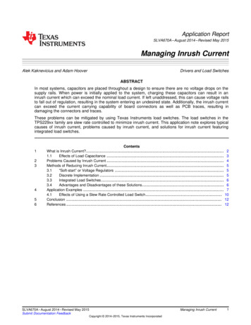
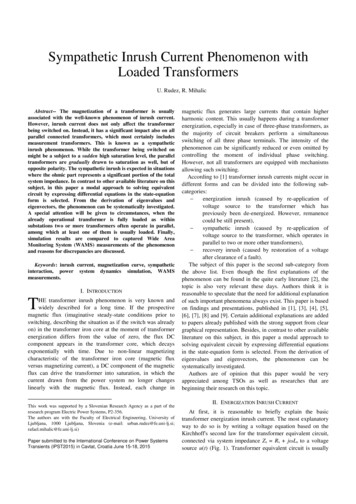
International Journal of Computer Applications (0975 – 8887)International Conference on Advances in Emerging Technology (ICAET 2016)Fig 3: The Diagram of virtual third harmonic restraintschemeFig 1: Inrush current generation in transformer3. METHODS3.1 Wavelet based methodDuring practical application of this method some problemsshould be taken care to maintain the reliability of the system.In this method first the transformer model with sufficientprecision are used for inrush current and short circuit currentmeasurement. The simulation shows current waveform withrespect to time (in seconds) for both the cases. Then wavelettransformation maps the time function of the result obtainedinto a two dimensional function of α and t.α is called scalingfactor and t is the change of the function along the time axis.Daubechies family wavelets are selected for the investigation.Results using wavelet transformation for inrush current andshort circuit current were quite different from each other andthus this method provides a way to distinguish inrush currentfrom short circuit current [43].1.The DC component should be removed in order to avoidthe mal operation of the relay.2.The symmetrical axis of the spiry pulse and data windowshould beat same position.3.The threshold value for the operation of relay should becarefully selected.3.2 Virtual third harmonic restraintIn this method the technology of waveform construction isused. Inrush current shown in fig.2 has a dominant evenharmonic component in it. By using waveform constructiontechnique the spiry pulse is moved for half cycle in backwarddirection and then reversed. This will form a waveform asshown in fig. 3.In fig.3; the practical inrush current shown bythin line is the same current waveform which has been shownin fig.2 while the thick line shows the result after applying theprocess of wave construction. Now this waveform contains adominant third harmonic component in it. However it to benoted that the third harmonic component is not really veryteeming in the whole process. It is only because of thewaveform construction the third harmonic comes in picture.This method offers many advantages over conventionalsecond harmonic relay. Firstly, the operating time hasreduced. Secondly, the restrain scheme can be performed byphase. Thirdly, the problem of symmetrical inrush current canalso be solved [35].3.3 Inductance based technique3.3.1 EII based techniqueThe change in Equivalent Instantaneous Inductance (EII) incase of inrush current and internal fault is the criteria used fordistinguishing inrush current and internal fault current.Experiments were conducted for verifying the performance ofthis technique and it was found that, there is extreme variationof the Equivalent Instantaneous Inductance (EII) for inrushcurrent, but the value of EII for faulty phase is almostconstant.During normal operating state of power transformer and forinternal fault condition, the iron core is not saturated and thevalue of magnetizing current is extremely small, which resultsin the approximately constant Instantaneous MagnetizingInductance (IMI) so the operation lies in the linear area of themagnetizing characteristic. But in case of inrush current thecore of transformer moves between saturation and nonsaturation region of operation due to this a sudden variation ofthe IMI, as shown in Fig. 4Fig 4: Diagram showing the variation of IMI waveformFig 2: Transformer inrush current diagram36
International Journal of Computer Applications (0975 – 8887)International Conference on Advances in Emerging Technology (ICAET 2016)There are two methods which are used to compute the valueof EII. First method is Indirect method while second methodis Direct method.Indirect method: When the supply of 50Hz is given to thetransformer the value of IMI varies and it has a fundamentalfrequency of 50Hz. The value of fundamental frequencycomponent of variation of IMI in case of normal operationand internal fault condition is zero and same is with the valueof EII while this is not the case for inrush current. Thus theabove mentioned criterion is used to differentiate inrushcurrent from internal fault or normal operation of transformer.If the magnitude of the fundamental frequency component inthe EII is more than the threshold or pick up value, then thereis inrush current in the transformer and the relay tripping isblocked, if it is more than the threshold value then relayoperating signal is send.Fig 5: Data window of filter algorithmWhen Fourier analysis for full window is done, the signalmagnitudes found for inrush current will not change or verylittle change will be there.Direct method: The RMS expression which gives the variationin EII is given asΔ k (1)k (2)Where, N is number of samples in a single frequency cycle .ΔL k̅ is criterion which sets the threshold and is used todistinguish the inrush current from the internal fault . If ΔL k̅exceeds a threshold or pick up value, the relay take it is asinrush current and the operation of relay is blocked. If thisvalue is less than the threshold value the relay takes it asinternal fault. The second method of analysis is successful inproducing the result in time as well as in frequency domainanalysis, while first method is effective only in frequencydomain [1].3.3.2 Instantaneous Inductance techniqueIn this method voltage and current signal are used to find thedifferential inductance of the transformer from the primaryside. The differential inductance is calculated from everyphase of the transformer. An algorithm is developed whichcompared this value of differential inductance with thethreshold value. If this value is more than the threshold valuethen it is inrush current else it is internal fault. The operatingtime of this method is also very less(5ms ,less than 1/4th ofthe power frequency cycle).This method works even whenthere is variation in the tapping of transformer, fault resistancecomes into picture, saturation of Current Transformer(CT)occurs [40].Fig 6: Data window of filter algorithmOn the contrary, when the analysis for short window byapplying short window algorithm was done, the value ofinrush current calculated by short-window filter algorithmwill be different from full window analysis. The variation inmagnetizing inductance is shown by solid lines in fig 6.However, this is not the case in the analysis of internal faultcurrent. The result is shown as the dotted line for full windowand solid line for short window filter algorithm (Fig.6 andFig.7)Fig 7: Magnitude of internal fault currentBased on the above discussion inrush current detectioncriterion is set. The detection criteria is given by3.4 Short Window Filter AlgorithmFor calculation of magnitude of transformer differentialcurrent the data window in one cycle Fourier filter isconsidered. Short data window is used for the detection ofinrush detection. Data window for filter algorithm is shown infig. 5. W1 shows the data window of Fourier filter which ishaving span of one power frequency cycle. W2 shows the datawindow for short-window filter algorithm and its span isshorter than span of one power frequency cycle.K (3)Where, Imshortwindow shows the magnitude evaluated by shortwindow filter, ImFourier shows the magnitude evaluated byFourier filter, N is sampling rate and Cth is the value of pickupthreshold for detecting inrush current in differential relay [36].3.5 Waveform Singularity TechniqueIn this technique, waveform singularity factor is used todifferentiate inrush current from internal fault current inpower transformer.Algorithm:For sinusoidal wave form,f(t) can be described asf(t) Asin(ωt θ)(4)37
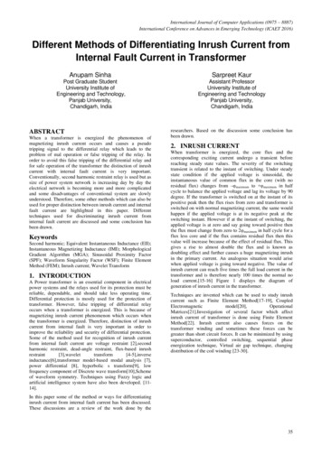
International Journal of Computer Applications (0975 – 8887)International Conference on Advances in Emerging Technology (ICAET 2016)Where, magnitude of sinusoidal waveform is denoted by A,Angular frequency of power signal is denoted by ω, and initialphase angle is represented by θ.Time interval for quarter cycle Δt is 0.5f (t) for instant t Δt isAcos(ωt θ)(5)f(t) for instantt Δt/2isAcos(ωt θ π/4)(6)g(t) is defined asg(t) f (t) f (t Δt) f (t Δt2)(7)The value of g(t) is constant with time and is ideally equal tozero, g(t).But in case of practical current waveform harmonicscomes into picture. So, a waveform singularity factor is usedto evaluate this differenceh(t) (8)e (9)Where, N is no. of samples per power frequency cycle. Wheninternal fault occurs the value of h(t) is zero and whenmagnetizing inrush current comes into picture this value isnon zero. If the WSF of every phase gets more than thethreshold or pickup value of 1.0, the relay will take it asinrush current and blocks the tripping. For all values less thanor equal to 1.0 the relay will take it as an internal fault andwill operate. The theoretical value of threshold is around zero.Thus h(t), also known as Waveform Singularity Factor (WSF)provides a measure to differentiate inrush current frominternal fault current [37].3.6 Sinusoidal Proximity FactorThe difference in the value of SPF in case of inrush currentand internal fault current is a measure to distinguish internalfault current from inrush current. The algorithm used for thecalculation of SPF is explained belowThe sinusoidal waveform can be expressed asf(t) Asin(ωt θ)(10)Where, magnitude of sinusoidal waveform is denoted by A,Angular frequency of power signal is denoted by ω, and initialphase angle is represented by θ.Let a signal f (t) is defined which has n even numbers ofsampling point. For sampling point at the instant tkf(tk) Asin(ωtk θ)(11)(14)Where, η is the SPF and abs stands for absolute differencebetween ρ(tk) and sin(2ωtk 2θ) .When internal fault is there,the value of SPF is close to zero and when magnetizing inrushcurrent is generated there is a drastic variation in the value ofSPF. Therefore, SPF is a measure to distinguish betweeninrush current and internal fault current. If the value of SPF ofsome phase is less than the threshold or pick up value of 0.5,the relay take this as an internal fault and gets tripped and forvalues greater than or equal to 0.5 the relay senses it as inrushcurrent and dismisses the tripping. This method is more usefulwhen the value of internal fault current is low [38].3.7 Identifying the Difference between theWaveform of Inrush Current andInternal Fault CurrentThe distinction between inrush current and internal faultcurrent can be done by identifying the difference between thewaveform of inrush current and internal fault current. Thedifferent features of inrush current and internal fault currentare shown in fig 8.(a)(b)Fig 8: (a) fault current, (b) inrush current.From the figure we can see that the internal fault currentwaveform has high slope at the time of switching and aftersome time duration its slope gets reduced while in case ofinrush current the slope at the time of switching is low and itincreases till the time current reaches its maximum value. Thisdistinction is used to discriminate the current as inrush currentor internal fault current. The methods are discussed as below.3.7.1 Improved Morphological GradientAlgorithmIn order to identify the slope feature of the waveform animproved Morphological Gradient Algorithm (MGA) is used.Fundamental morphological operator dilation and erosion areused in this scheme. Dilation and erosion for a onedimensional signal is given as(fg) (x) max {f(x-s) g(s),x Df,s(f g) (x) max {f(x s)-g(s), x Df,sf(tk) for the instant t Δt is(12)Normalizing f(t) and multiply equation (11) and (12)ρ(tk) sin(2ωtk 2θ)η(tk) abs(ρ(tk) sin(2ωtk 2θ))Dg}(15)sTime interval for quarter cycle Δt is 0.5Acos(ωtk θ)sinusoidal proximity factor (SPF) is used to evaluate thisdifference.(13)This is the expression for pure sine wave. But for practicalcurrent waveform harmonics comes into picture. So aDg}(16)sWhere f is the field, g stands for structuring element (SE),field of definition of f and g are denoted as Df and Dgrespectively. For edge detection morphological gradient usedis:G(f) (f g) – (f g)(18)38
International Journal of Computer Applications (0975 – 8887)International Conference on Advances in Emerging Technology (ICAET 2016)Structuring element defined to find the rising and fallingedges areg {01,02, .0l}g- (19){01,02 .0l}(20)-Where g is used for rising edge and g is used for fallingedge. For the length of flat SE of 3, the improvedmorphological gradient for inrush current and internal faultcurrent is as shown in figure 9(a) and 9(b).Fig 10: Flow chart of the scheme.3.7.2 Using mathematical MorphologyFig 9: (a) Morphological gradient for inrush current.The above discussed morphological approach fails when CTis saturated so a new method is developed usingmorphological fundamentals as described above. It uses twodifferent algorithms the first algorithm can discriminatebetween inrush and internal fault currents when there is no CTsaturation. When CT gets saturated, the first algorithm fails toprovide a decision. In this case, the second algorithm whichuses a symmetrical morphological gradient criterion istriggered automatically to differentiate between internal faultand inrush current in the system. This method can also beused to detect sympathetic inrush current [42].3.7.3 Wavelet Based Technique by usingFinite Element MethodFig 9: (b) Morphological gradient for internal faultcurrentBased on these differences between the patterns of waveform,the inrush current can be distinguished with internal faultcurrent in the sampling window of half a long cycle. For thesake of quantification the criterion used for discrimination is(17)Where, current signal in the data sampling window isrepresented by Is and morphological gradient is representedby Gs. The value of σ is very high in case of inrush current ascompared to its value in case of internal fault current. For thenext half cycle, if the gradient result shows a flat waveform,then it is inrush current otherwise, there is internal fault [41].The above process is explained with the help of flow chart asshown in figure 10.Discrete wavelet transform (DWT) is applied to thedifferential current and distinct characters and features forinrush current and internal fault current is extracted based onthe wavelet components. With the help of these character andfeatures the current will be recognized as inrush current orinternal fault current. The ability of the wavelet transform tofocus on short time intervals for high frequency componentsand long-time interval for low frequency componentsprovides a better way of investigation for signals which havelocalized impulses and oscillation. So, wavelet decompositionis very helpful for studying transient signals. It also helps infinding a much better current characterization with morereliable distinction. The process of execution of DWT isshown in fig. 11 in which s denotes the original signal andhigh pass filter and low pass filter are denoted as HPF andLPF respectively.Fig 11: Implementation procedure of DWT.By observing the waveform for inrush current and internalfault current (fig. 8) it can be said that in case of fault currentthe magnitude of high frequencies at starting time has fallingtrend, while in case of inrush current the trend has a rising.These trends and features are found in the frequency level D339
International Journal of Computer Applications (0975 – 8887)International Conference on Advances in Emerging Technology (ICAET 2016)when simulation based on Finite Element Method was done.Finite element method gives a more realistic method ofsimulation. Thus the above mentioned criteria can be used fordifferentiating inrush current from fault current. This methodis relatively faster method and can differentiate inrush currentfrom fault current in less than quarter a cycle if the supply isof 50Hz [39].4. CONCLUSIONS AND FUTURESCOPEAmong the above mentioned techniques all the techniques canbe used in real life situation but instantaneous inductance andwavelet based technique are relatively faster as compared toother techniques. Also, Instantaneous inductance techniqueand morphological technique are better than other techniquesbecause they work even when CT is saturated. For futurescope, efforts are needed to remove the DC decayingcomponent. Better mechanism for finding optimum positionof data window needs to be developed. The sensitivity for themethod of sinusoidal proximity factor should not be limited tolow level internal faults only. The application of EII can beextended to transformers with more number of turns. Effortsshould be made to reduce the operating time of relay. Morestudy is needed in setting up the threshold criterion of therelay.5. REFERENCES[1] Ge Baoming, A T. de Almeida, ZQionglin, andW.Xiangheng,IEEE Trans. on Power Delivery, Anequivalent instantaneous inductance based technique fordiscrimination between inrush current and internal faultsin power transformers, 20, 2473-2482, (2005).[2] J. S. Thorp and A. G. Phadke,,IEEE Trans. Power Appl.Syst.,A microprocessor based three phase transformerdifferential relay,PAS-101, 426–432, (1982).[3] A. G. Phadke and J. S. Thorp, IEEE Trans. on PowerApparatus and Systems, A new computer-based fluxrestrained current-differential relay for powertransformer protection,PAS-102, 3624-3629, (1983).[4] M. Jamali, M. Mirzaie, S. A. Gholamian and S.MahmodiCherati, IAPEC IEEE, A Wavelet-BasedTechnique for Discrimination of Inrush Currents fromFaults in Transformers Coupled with Finite ElementMethod, 138-142, (2011).[5] X.L.Feng, J.C.Tan, Z.Q.Bo, UPEC IEEE, A new wavelettransform approach to discriminate magnetizing inrushcurrent and fault current,3,876-880, (2006).[6] K. Inagaki, M. Higaki, Y. Matsui, K. Kurita, M. Suzuki,K. Yoshida, and T. Maeda, IEEE Trans Power Del.Digital protection method for power transformers basedon an equivalent circuit composed of inverseinductance3, 1501–1510, (1988)[7] T. S. Sidhu and M. S. Sachdev, IEEE Trans. Power Del.,On line identification of magnetizing inrush and internalfaults in three phase transformer, 7 , no. 4, 1885–1891,(1992).[8] K.Yabe, IEEE Transactions on power delivery, Powerdifferential method for discrimination between fault andmagnetizing inrush current in transformers,12, no. 3,1109-1118, (1997)[9] Q. Zhang, S. Jiao, S. Wang, ICIEA IEEE, IdentificationInrush Current and Internal Faults of Transformer basedon Hyperbolic S-transform,258-263,(2009).[10] C. Jettanasen, C. Pothisarn , J. Klomjit andA.Ngaopitakkul, ICEMS IEEE, Discriminating amongInrush Current, External Fault and Internal Fault inPower Transformer using Low Frequency ComponentsComparison of DWT,1-6, (2012).[11] L. G. Perez, A. J. Flechsig, J. L. Meador, and Z.Obradoviic, IEEE Trans. Power Del., Training anartificial neural network to discriminate betweenmagnetizing inrush and internal faults, 9, no. 1, 434–441, (1994).[12] Á. L. Orille-Fernández, N. K. I. Ghonaim, and J.A.Valencia, IEEE Trans. Power Del.,A FIRANN as adifferential relay for three phase power transformerprotection, 16, no. 2, 215–218,(2001).[13] M. R. Zaman and M. A. Rahman, IEEE Trans. PowerDel., Experimental testing of the artificial neural networkbased protection of power transformers,13, no. 2, 510–517, (1998).[14] A. Wiszniewski and B. Kasztenny, IEEE Trans. PowerDel.,A multi-criteria differential transformer relay basedon fuzzy logic, 10, no. 4, 1786–1792, (1995).[15] ] S.V. Kulkarni, S.A. Khaparde, Transformer EngineeringDesign and Practice, New york : Marcel Dekker, 2004.[17] Z. Liu, S. Liu, and O. A. Mohammed, IEEE Transactionson Magnetics, A Practical Method for Building the FEBased Phase Variable Model of Single PhaseTransformers for Dynamic Simulations,43,no. 4, 17611764, (2007).[18] J.Takehara, M.Kitagawa, T.Nakata and N.Takahashi,IEEE Trans. Magn., Finite element analysis of inrushcurrents in three phase transformer,23, 2647-2649, no.5,(1987).[19] D.Phaengkieoi,W.Somlak2andS.Ruangsinchaiwanich, ICEMS IEEE, Transformer Designby Finite Element Method with DOE Algorithm.,22192224 (2013).[20] R. Yacamini,H. Bronzeado, IEE Proceedings science,measurement and technology, Transformer inrushcalculations using a coupled electromagnetic model,141,491-498 (1994).[21] J. Jesus Rico, Enrique Acha and Manuel Madrigal, IEEETransactions on Power Delivery, The Study of InrushCurrent Phenomenon Using Operational Matrice, 16,231-237, no. 2, (2001).[22] M.R.Feyzi and M.B.B.Sharifian, IPEMC IEEE,Investigation on the factors affecting inrush Current ofTransformers Based on Finite Element Modelling,1, 1-5,(2006).[23] JawafFaiz, Bashir Mahdi Ebrahimi and TahereNoori,IEEE Trans Magn.,Three and two dimensional finiteelement computation of inrush current and short circuitelectromagnetic forces on windings of a three phase coretype power transformer,44, no. 5, 590-597,(2008).40
International Journal of Computer Applications (0975 – 8887)International Conference on Advances in Emerging Technology (ICAET 2016)[24] W.Neves, D. Fernandes , F. J. A. Baltar , A. J. P.Rosentino , E, Saraiva , A. C. Delaiba , R. Guimaraes ,M. Lynce , Jose Carlos de Oliveira, EPQU IEEE, Acomparative investigation of electromechanical stresseson transformers caused by inrush and short-circuitcurrents,1-6,(2011).[25] M. Steurer and K. Fröhlich, IEEE Trans.Power Del.,Theimpact of inrush currents on the mechanical stress ofhigh voltage power transformer coils, 17, no. 1, 155–160,(2002).[26] A.A. Adly, IEEE Trans Magn. ,Computation Of Inrushcurrent forces on transformer windings, 37,no. 4,28552857,(2001)[27] C.K Cheng, T.J.Liang, J.F. Chen,S.D. Chen andW.H.Yang , IEE Proc. Electr. Power Appl., Novelapproach to reducing the inrush current of a powertransformer, 151, No.3, 289-295 (2004).[28] Y. Cui, S. G. Abdulsalam, S. Chen and W. Xu,IEEETrans. Power Del., A sequential phase energizationtechnique for transformer inrush current reduction part1,20, no. 2, 943–949, (2005).[29] W. Xu, S. G. Abdulsalam, Y. Cui, and X. Liu,IEEETrans. Power Del., A sequential phase energizationtechnique for transformer inrush current reduction part2,20, no. 2, 950–957,(2005).[30] H. S. Nankani1, R. B. Kelkar, International Journal ofScience and Research, Review on Reduction ofMagnetizing Inrush Current in Transformer, 4, 234242,(2015).[31] M.Jing, W.Zengping, Power Engineering SocietyGeneral Meeting IEEE, A Novel Algorithm forDiscrimination Between Inrush Currents and InternalFaults Based on Equivalent Instantaneous LeakageInductance., 1-5, (2007).Transform Based Discrimination Between Inrush andInternal Fault of Indirect Symmetrical Phase ShiftTransformer,1-5, (2014).[34] V. Barhate, International Journal of Electrical andElectronics Engineering Research, A review ofdistinguishing schemes for power transformer’smagnetizing inrush and fault currents, 3, 277-284,(2013).[35] Y. Hu, D. Chen, X. Yin and Z. Zhang, Transmission andDistribution Conference and Exposition,IEEE PES, ANovel Theory for Identifying Transformer MagnetizingInrush Current, 1, 274-278,(2003).[36] Z. Han, S. Liu, S.Gao, Z. Bo, UPEC IEEE,A NovelDetection Criterion for Transformer Inrush Based onShort-Window Filter Algorithm, 1-5, (2008).[37] J. Ma, Z. Wang, J. Wu, IPEC IEEE, A novel method fordiscrimination of internal faults and inrush currents byusing waveform singularity factor, 1035-1039, (2010).[38] J. Ma, D Ye, Z. Wang, J, Wu IPEC IEEE, IdentifyingInrush Current Using Sinusoidal Proximity Factor, 215219, (2010).[39] M. Jamali, M. Mirzaie, S. A.Gholamian, S. M.Cherati,IAPEC IEEE,A Wavelet-Based Technique forDiscrimination of Inrush Currents from Faults inTransformers Coupled with Finite Element Method, 138142,(2011).[40] H. Abniki, H. Monsef, P. Khajavi, and H. Dashti, MEPSIEEE, A Novel Inductance-Based Technique forDiscrimination of Internal Faults from MagnetizingInrush Currents in Power Transformer, 1-6, (2010).[41] W.C. Wu, T. Y. Ji, M. S. Li; L. L. Zhang; Q. H.Wu,Power and energy society general meeting ogical Gradient Algorithm, 1-5, (2013).[32] J.Ma, Z.Wang, S.Zheng, T.Wang, Q. Yang, CanadianJournal of Electrical and Computer Engineering, A newalgorithm to discriminate internal fault current and inrushcurrent utilizing features of fundamental current, 36, 2631,(2013).[42] W. Wu, T. Ji, M. Li, Q. Wu, IET generation,transmission and distribution, Using mathematicalmorphology to discriminate between internal fault andinrush current of transformers, 10 , 73-80, (2016).[33] S.K Bhasker, M. Tripathy,V Kumar, PES generalmeeting conference and exposition IEEE, Wavelet[43] S.Y Hong and W. Qin, ICPST IEEE, A wavelet-basedmethod to discriminate between inrush current andinternal fault, 2, 927-931, (2000).IJCATM : www.ijcaonline.org41
inrush current can reach five times the full load current in the transformer and is therefore nearly 100 times the normal no load current.[15-16] Figure 1 displays the diagram of generation of inrush current in the transformer. Techniques are in