Transcription
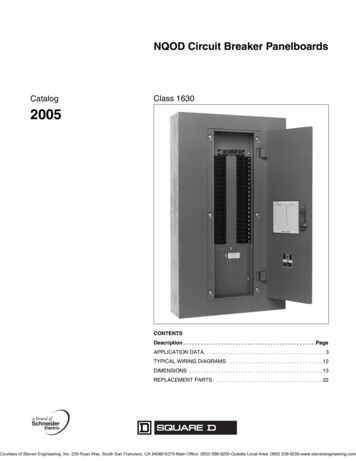
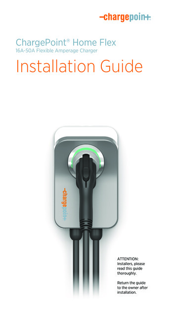
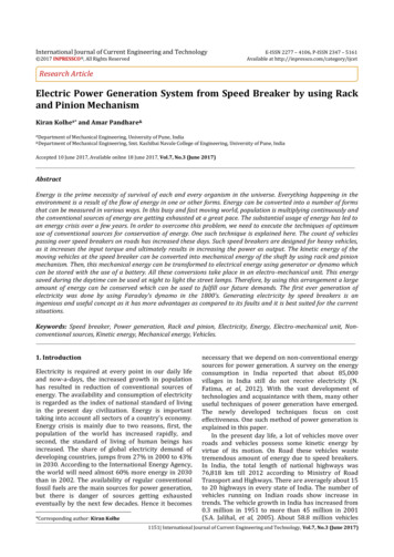
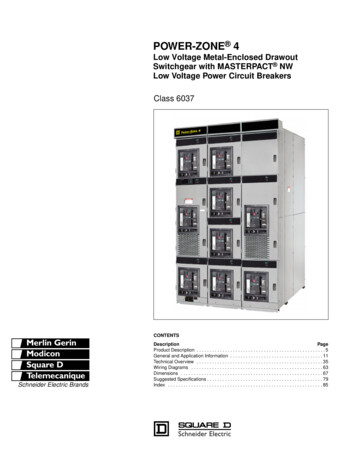
Application Note 105Circuit Breaker Operation &its load calculationsAbstractCircuit breaker is very effective protection device in anylighting application. Improper loading of MCB might leadto “Nuisance Tripping”, damage the application ordamage the circuit breaker and even cause fire breakout.This document will drive you through the briefintroduction of circuit breaker, its operation and loadcalculations.trip unit is temperature sensitive and the magnetic tripunit is current sensitive. These thermal and magnetic tripunits are independent and act mechanically with theMCB trip mechanism to open the MCB contacts.Miniature Circuit Breaker (MCB)A circuit breaker is a protective device to protect theapplication during an overcurrent condition. MCB is aresettable protective device that protects againstsituations like Overload and Short Circuit.In other words: Under normal condition the device willcarry the load current and during the fault/abnormalcondition the device will automatically break andautomatically reset as the fault condition is eliminateda. Cross Sectional DiagramFigure 2. Cross Sectional view to show Magnetic andThermal Trip functionsThermal / Overload protection:During continuous overload condition thermal trip unitgets activated and protects the circuit. The thermal unitis comprised of a bimetal lever located behind the MCBtrip bar and is in the direct current carrying path. Duringoverload, the increased current flow heats the bimetallever causing it to bend. As the lever bends it pulls thetripping element which opens the MCB contacts.Fig 1. Cross Sectional view of a MCBb. Modes of OperationThe overload current and time required for the bimetal tobend and trip the breaker are inversely proportional.Hence, as current increases the tripping time reduces.Thermal and Magnetic trip definitionMCB uses an electromechanical trip unit to open thecontacts during an overcurrent condition. The thermal ERP Power, LLC-1-April 2018
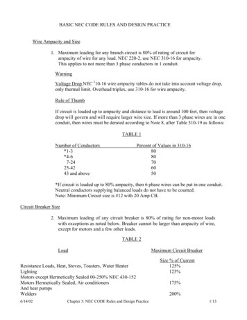
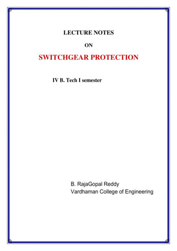
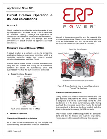
Application Note 105Magnetic / short circuit protection:A short circuit current activates the magnetic tripfunction. The magnetic trip unit is comprised of anelectromagnet coil, an armature and movable contact.Figure 3. Cross Sectional view to show MagneticTrip functionsWith short circuit condition, a high magnitude of currentpasses through the coils creating a magnetic field thatattracts the movable armature towards the fixedarmature. The tripping lever is pushed against themovable contact and the contacts are opened.Manual Protection:User can manually control the Circuit On/Off Conditions,by dropping the operator control switch.c. Trip Curves:The tripping characteristic of MCB is plotted as trippingtime Vs. current level. The curve shows the amount oftime required for a MCB to trip at a given overcurrent orshort circuit condition.As per IEC 60898-2, Electrical accessories – Circuitbreakers for overcurrent protection for household andsimilar installations, Part 2: Circuit-breakers for AC andDC operation. The trip curve plotted as below,-2-Figure 4. Trip Curve as per IEC 60898-2The above picture defines tripping and non-trippingregion. If the In-rush falls under tripping region, the MCBwill trip instantaneously and Inrush current under nontripping region is safe for operation.d. MCB Types: TYPE B: The tripping limits are between 3 and 5times the current rating of the MCB. Example:10A MCB will trip between 30A and 50A in anovercurrent condition. TYPE C: The tripping limits are between 5 and10 times the current rating of the MCB. Example:10A MCB will trip between 50A and 100A in anovercurrent condition. TYPE D: The tripping limits are between 10 and50 times the current rating of the MCB. Hereapplications are with products generating veryhigh inrush currents. Such as Heavy Motors andSolenoids*Limits as per IEC/EN 60898**Electrician’s usually consider Type B for Householdlighting and Type C for commercial lightingapplicationerp-power.com
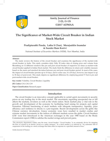
Application Note 105Inrush CurrentInput current of short duration during initial start-up thatis much greater than the operating or steady statecurrent. We can say that during start-up LED driver drawhigher than normal operating current for a short duration.This current occurs because of various capacitorsdistributed throughout the design. These capacitorsperform different functions in the design like limitelectromagnetic interference, filter switching noise,and/or store energy. By and large the greatestcontributors to inrush are the energy storage capacitors.Simply put, a capacitance value times the change involtage across it divided by the time it takes for thatvoltage to change causes a current pulse to flow that isof the same time duration as the voltage change. This isgiven in the equation below.C x V(t) / t i(t)So if the capacitor value and voltage change are largebut occur in a very short amount of time, there is a largecurrent flow through the capacitor. That current drawnfrom the AC line is inrush.A turn-on at zero voltage is relatively soft. The change incapacitor voltage can be muted. In this case the inrushcurrent is drawn during the normal change of the linevoltage in the appropriate line cycle time and/or with anyadditional circuitry that may try to push a higher voltagein a shorter amount of time across internal capacitors;however, here the inrush will be much less than if turn-onis at 90 or 270 . Of course, turn-on at the 90 maximumor 270 minimum means the change in the capacitorvoltage expected is near instantaneous; hence, a largepositive (at maximum) or negative (at minimum) currentspike must occur that is more or less superimposedupon that which would have occurred if turn-on was atthe zero voltage crossing.The inrush current spike itself has a magnitude and awidth. It’s normally characterized for its peak and timewidth (the time at which 10% magnitude occurs). It’salso measured at some source impedance, the highestnominal AC line voltage of specified driver operation, fullload, a nominal 25 C temperature, and a time at which ithas not been recently switched on. The sourceimpedance is a standard value given in NEMA 410.a. Waveform:LED Drivers powered by the AC line see a sinusoidalwaveform (as in the figure below). There are 360 to onecomplete AC line cycle, just as a circle or a compass has360 . When a LED Driver is energized (start-up) by thepower line, it occurs (turn-on) at approximately 1 of the360 line cycle. In real life and with manual switches younever know what degree that turn-on will occur; but itmatters. A sine wave has a peak and a trough at 90 and270 . These degrees are where the varying magnitudesine wave respectively reaches its maximum andminimum peak voltage values. Also, the 0 , 180 , and360 points are where the sine wave voltage is exactlyzero.Figure 6. Inrush current waveform of ESS020W-0700-24b. Effects of high inrush current:High inrush current can create potential negative effects.NEMA 410 defines limits of acceptable inrush currents toprevent this. Usually drivers are designed to stay withinthe limits. The highest nominal voltage on a universaldriver would be 277 Vac, this will obviously vary fordrivers with other operating voltages. Full load is thenormal test load. A 25 C cold start is considered worstcase. Lastly, you want all the internal capacitors to befully discharged so that no residual voltages present.Figure 5. Standard Sine Wave-3-erp-power.com
Application Note 105Unacceptable inrush can potentially damage relays.Standard relays can switch anywhere in a standard linecycle. As discussed above, switching at certain parts ofthe line cycle will allow for a maximum inrush. This cancause damage by degrading relay contacts andsometimes welding them closed, due to arcing at thecontact. Standard component analysis techniques mustbe employed to determine the load derating to use on arelay, as well as the kind of inrush it can accept.c. Relation of Inrush Current to MCB Trip Curve:Under high inrush current circumstances MCB can be autilized as a protection device, it can open the circuitinstantaneously and later can be returned to nominaloperating condition without causing any damage to theapplication, once the circuit recovers from overcurrentcondition.For LED lighting application, usually user prefers type B,as per Fig 4 for instantaneous pick up trip point time isless than 0.002S. if the LED driver inrush current lowerthan 100A ( T 0.002S). Then you can neglectconsidering the inrush current for the MCB loadcalculations. Concluding on 109 units per 10A, Type B MCBIn case of inrush current higher than 100A with T 0.002 S, then follow procedure as below, Correlate the T with I/IN from Fig 4Compute the Multiplication factor for the MCBCurrent ratingDivide the value by In-rush currentFinal value will be the No. of units per MCBFor example, consider inrush 120 A with T of 0.1 S,MCB Load calculation would be as below,Correlating above value from Fig 4, at T 0.1 S 10A,type B MCB will trip between 30 to 50 A load current,hence the example application, will instantaneously tripon turn on.So selecting 32 A, Type C MCB will trip between 160 to320A load current, hence user can load max of 1 unit onthis MCBHigh inrush current applicationexamplesMCB Load CalculationConsidering as example ERP LED driverESS020W-0700-24, below are listed parameters modelNominal Input Voltage: 230 VacInput Current: 0.083 AInrush Current: 10.71 A (as per Picture. 6) T (Inrush current): 0.0006SMCB Type: 10A rated current, Type BCheck if the inrush current is less than 0.002S, ifyes proceed as belowNon tripping current of 10A, Type B, MCB (Int):1.13 x MCB rated current1.13 x 10 11.3 ANumber of load per MCB Int / Input current11.3 / 0.083 136.1136 units per MCB (100% load)80% MCB load calculation Int x 0.8(Considering the safety factor of 20% and notloading the MCB to its 100%)11.3 x 0.8 9.04 A9.04 / 0.083 108.9109 units per MCB-4-Inrush Current of a Motor Inrush Current of a Solenoiderp-power.com
Application Note 105 Here you can observe from the above, that thepeak current remains for a longer duration, thenstabilizes over time Hence selection of Circuit Breaker depends onthe Inrush current, else it might lead to “NuisanceTripping”Effects of improper MCB loading Danger of fire: if the MCB is oversized and thewire gauge used in the electrical system is notappropriate, the MCB will not trip and lead to firebreakout Nuisance Tripping: This might be due to “HighInrush Current” and result of not considering for MCBload calculation Damage the MCB Damage the application circuitSummaryConsider inrush current of the device or equipment,while selecting MCB type and its load. Inrush currentwith T 0.002S can be neglected for MCB loadcalculation. Compute the MCB load considering thecontinuous input current. For higher inrush currentapplications, correlate the inrush current with the MCBtrip curve and conclude the MCB load.References ABB – Miniature Circuit Breaker, Application GuideSchneider Electric - Circuit Breaker CharacteristicTrip Curves and Coordination – Data Bulletin #0600DB0105MK by Honeywell – Sentry Technical – CircuitProtectionThomas Research Products – Inrush white paperThe information in this document is subject to change without notice. Other trademarks, product, and company names are the property of their respective owners and do not implyspecific product and/or vendor endorsement, sponsorship or association. This document is provided for informational purposes only and is not a warranty or a specification. Forproduct specifications, please see the data sheets available at www.erp-power.com. For warranty information, please contact ERP Sales at SaveEnergy@erp-power.com.U.S.A. HeadquartersTel: 1-805-517-1300893 Patriot Drive, Suite EMoorpark, CA 93021CHINA OperationsTel: 86-756-6266298No. 8 Pingdong Road 2Zhuhai, Guangdong,China 519060-5-SaveEnergy@erp-power.comerp-power.com
Consider inrush current of the device or equipment, while selecting MCB type and its load. Inrush current with T 0.002S can be neglected for MCB load calculation. Compute the MCB load considering the continuous input current. For higher inrush current applications, c