Transcription
A Heuristic for Including Black Box Analysis Tools into aGeometric Programming FormulationbyCody Jacob KarcherB.S., Aerospace Engineering, University of Maryland, College Park, 2014Submitted to the Department of Aeronautics and Astronauticsin partial fulfillment of the requirements for the degree ofMaster of Science in Aeronautics and Astronauticsat theMASSACHUSETTS INSTITUTE OF TECHNOLOGYMay 2017c Massachusetts Institute of Technology 2017. All rights reserved.Author . . . . . . . . . . . . . . . . . . . . . . . . . . . . . . . . . . . . . . . . . . . . . . . . . . . . . . . . . . . . . . . . . . . . . .Department of Aeronautics and AstronauticsMay 25, 2017Certified by . . . . . . . . . . . . . . . . . . . . . . . . . . . . . . . . . . . . . . . . . . . . . . . . . . . . . . . . . . . . . . . . . .Warren W. HoburgBoeing Assistant ProfessorThesis SupervisorAccepted by . . . . . . . . . . . . . . . . . . . . . . . . . . . . . . . . . . . . . . . . . . . . . . . . . . . . . . . . . . . . . . . . .Youssef M. MarzoukAssociate Professor of Aeronautics and AstronauticsChair, Graduate Program Committee
2
A Heuristic for Including Black Box Analysis Tools into aGeometric Programming FormulationbyCody Jacob KarcherSubmitted to the Department of Aeronautics and Astronauticson May 25, 2017, in partial fulfillment of therequirements for the degree ofMaster of Science in Aeronautics and AstronauticsAbstractRecently, geometric programming has been proposed as a powerful tool for enhancing aircraft conceptual design. While geometric programming has shown promise in early studies,current formulations preclude the designer from using black box analysis codes which areprolific in the aircraft design community. Previous work has shown the ability to fit datafrom these black box codes prior to the optimization run, however, this is often a time consuming and computationally expensive process that does not scale well to higher dimensionalblack boxes. Based upon existing iterative optimization methods, we propose a heuristic forincluding black box analysis codes in a geometric programming framework by utilizing sequential geometric programming (SGP). We demonstrate a heuristic SGP method and applyit to a solar powered aircraft using a black boxed GP compatible profile drag function. Using this heuristic algorithm, we achieve less than a 1% difference in the objective functionbetween a direct implementation of the constraint and a black box implementation of theconstraint.Thesis Supervisor: Warren W. HoburgTitle: Boeing Assistant Professor3
4
AcknowledgmentsI fully believe that I would not be here without the contributions of many others who helpedme and guided me along the way. I would first like to thank my advisor Warren Hoburg forhis many contributions and inputs to this work, as well as John Hansman for his guidance andexperience. I have also had the great pleasure of working with a number of exceptional anddedicated engineers at Boeing: Bob Liebeck, David Lazzara, Norm Princen, Chris Droney,Sean Wakayama, Jeff Fukushima, and Dean Hawkinson. A special thanks to my family atCity on a Hill Church and the Cambridge Community Group for being a constant source ofstrength and joy. I would also like to thank my various friends with whom grabbing lunch hasbecome regular practice: Cory Frontin, Kevin Archibald, David Miculescu, Devon Jedamski,Sam Schreiner, and Shane Pratt. Thanks also to my friends in the International Center forAir Transportation and the Aerospace Computational Design Laboratory for their ongoingfriendship and support. Thanks also to the teaching staff of 16.82x, Tony Tao, JacquieThomas, Jennifer Craig and the various student’s I have had the pleasure of teaching overthe past year. I would also like to thank Albion Bowers and Trevor Gardner, for showing mehow to be a godly man while pursuing after scientific discovery. Also to my various teachersfrom the Grove City Area School District who helped me achieve my goals and played alarge part in my academic success. I am indebted to the many University of Maryland andMIT faculty and staff who have helped me become the engineer that I am today, particularlyInderjit Chopra, Raymond Sedwick, Derek Paley, Will Fourney, Aileen Hentz, Mark Drela,Robert Haimes, Ping Lee, Jei Lee Freeman. I would also like to thank my many friends fromTeam Gamera, particularly Will Staruk and PK Koliais for their friendship and mentorship.Thanks also to my great friends from the MIT Curling Club: Nate Bailey, Alex Hull, GregDooley, and Andrea Dubin with whom I have many thoughtful discussions. A special thanksto Kika Arias for her support throughout the writing process. I would most like to thankmy parents and brother, Sandra, Victor and Christopher Karcher, for their endless love andsupport. Finally, to my Heavenly Father, without whom I am nothing.5
6
Contents1 Importance of Conceptual Design151.1The Three-Phase Aircraft Design Process . . . . . . . . . . . . . . . . . . . .151.2Conceptual Aircraft Design171.3Trend of Increasing Design Time. . . . . . . . . . . . . . . . . . . . . . . . . . . . . . . . . . . . . . . . . . . . . . . . . .2 MDAO in Aircraft Design21232.1Overview . . . . . . . . . . . . . . . . . . . . . . . . . . . . . . . . . . . . . .232.2Definition of a Discipline . . . . . . . . . . . . . . . . . . . . . . . . . . . . .242.2.1Performance and Mission Analysis . . . . . . . . . . . . . . . . . . . .252.2.2Aerodynamics . . . . . . . . . . . . . . . . . . . . . . . . . . . . . . .262.2.3Propulsion . . . . . . . . . . . . . . . . . . . . . . . . . . . . . . . . .262.2.4Weights and Structures . . . . . . . . . . . . . . . . . . . . . . . . . .262.2.5Stability and Control . . . . . . . . . . . . . . . . . . . . . . . . . . .27Analysis . . . . . . . . . . . . . . . . . . . . . . . . . . . . . . . . . . . . . .272.3.1Notion of Fidelity . . . . . . . . . . . . . . . . . . . . . . . . . . . . .282.3.2High Fidelity “Black Box” Analyses . . . . . . . . . . . . . . . . . . .30Optimization . . . . . . . . . . . . . . . . . . . . . . . . . . . . . . . . . . .302.4.1Formulating Mathematical Optimization Problems . . . . . . . . . .31Takeaways from MDAO . . . . . . . . . . . . . . . . . . . . . . . . . . . . .332.32.42.53 Convex Optimization and Geometric Programs735
3.1Convex Optimization . . . . . . . . . . . . . . . . . . . . . . . . . . . . . . .353.2The Geometric Programming Formulation . . . . . . . . . . . . . . . . . . .363.3Geometric Programming for Conceptual Design . . . . . . . . . . . . . . . .383.4Advantages of the Geometric Programming Approach to Conceptual Design393.5Geometric Programs and Black Boxes . . . . . . . . . . . . . . . . . . . . . .404 Iterative Optimization Methods434.1Sequential Quadratic Programs . . . . . . . . . . . . . . . . . . . . . . . . .434.2Signomial Programs . . . . . . . . . . . . . . . . . . . . . . . . . . . . . . . .474.3Sequential Convex Programs . . . . . . . . . . . . . . . . . . . . . . . . . . .504.3.1Sequential Geometric Programming . . . . . . . . . . . . . . . . . . .51General Iterative Methods with Black Boxes . . . . . . . . . . . . . . . . . .525 Proposal for a Heuristic Sequential Geometric Programming Algorithm534.45.1Algorithm Introduction . . . . . . . . . . . . . . . . . . . . . . . . . . . . . .535.2Initialization . . . . . . . . . . . . . . . . . . . . . . . . . . . . . . . . . . . .545.3Variable Handling . . . . . . . . . . . . . . . . . . . . . . . . . . . . . . . . .545.4Surrogate Modeling . . . . . . . . . . . . . . . . . . . . . . . . . . . . . . . .545.5Black Box Considerations . . . . . . . . . . . . . . . . . . . . . . . . . . . .565.6Creating GP Compatible Constraints . . . . . . . . . . . . . . . . . . . . . .565.6.1Soft-Max Affine (SMA) Functions . . . . . . . . . . . . . . . . . . . .565.6.2Number of SMA Terms . . . . . . . . . . . . . . . . . . . . . . . . . .575.6.3Interval of Sampling . . . . . . . . . . . . . . . . . . . . . . . . . . .575.6.4Selecting Points in the Interval . . . . . . . . . . . . . . . . . . . . .595.7Implementing Trust Regions . . . . . . . . . . . . . . . . . . . . . . . . . . .595.8Convergence Criteria . . . . . . . . . . . . . . . . . . . . . . . . . . . . . . .606 Implementation of the Sequential Geometric Programming Algorithm ona Solar Powered Aircraft636.163Solar Aircraft Test Problem . . . . . . . . . . . . . . . . . . . . . . . . . . .8
6.2User Defined Inputs . . . . . . . . . . . . . . . . . . . . . . . . . . . . . . . .656.2.1Initial Guess Values . . . . . . . . . . . . . . . . . . . . . . . . . . . .656.2.2SMA Model Parameters . . . . . . . . . . . . . . . . . . . . . . . . .656.2.3Initial Sampling Interval Parameters . . . . . . . . . . . . . . . . . .656.2.4Sampling Interval Tightening Parameters . . . . . . . . . . . . . . . .666.2.5Monomial Mode Parameters . . . . . . . . . . . . . . . . . . . . . . .667 Results of the Sequential Geometric Programming Algorithm697.1Success Metrics . . . . . . . . . . . . . . . . . . . . . . . . . . . . . . . . . .697.2Algorithm Performance . . . . . . . . . . . . . . . . . . . . . . . . . . . . . .708 Conclusions and Future Work758.1Summary . . . . . . . . . . . . . . . . . . . . . . . . . . . . . . . . . . . . .758.2Future Work . . . . . . . . . . . . . . . . . . . . . . . . . . . . . . . . . . . .768.2.1Utilizing Signomial Surrogate Models . . . . . . . . . . . . . . . . . .768.2.2Implementing New Black Boxes . . . . . . . . . . . . . . . . . . . . .768.2.3Developing a General SGP Algorithm . . . . . . . . . . . . . . . . . .77A Full Report of Design Results83A.1 Original Formulation From Burton . . . . . . . . . . . . . . . . . . . . . . .83A.2 Case 1: Hoburg Constraint Implemented as a Geometric Program . . . . . .93A.3 Case 2: Hoburg Constraint Implemented as a Sequential Geometric Program 1039
10
List of Figures1-1 Three phases of aircraft design . . . . . . . . . . . . . . . . . . . . . . . . . .161-2 Knowledge, cost committed and design freedom in the design process [1] . .171-3 Aircraft concept and experimental airplane . . . . . . . . . . . . . . . . . . .181-4 Aircraft concept linking requirements, constraints and objectives [2] (Adaptedfrom [3]) . . . . . . . . . . . . . . . . . . . . . . . . . . . . . . . . . . . . . .201-5 Increasing development time of modern aircraft [4] . . . . . . . . . . . . . . .222-1 Methods for system decomposition . . . . . . . . . . . . . . . . . . . . . . .242-2 Aerodynamics fidelity tree . . . . . . . . . . . . . . . . . . . . . . . . . . . .293-1 Example of a monomial family . . . . . . . . . . . . . . . . . . . . . . . . . .373-2 Some posynomial examples . . . . . . . . . . . . . . . . . . . . . . . . . . . .374-1 Example optimization problem . . . . . . . . . . . . . . . . . . . . . . . . . .454-2 The solution of an example sequential quadratic Program . . . . . . . . . . .464-3 An example signomial program . . . . . . . . . . . . . . . . . . . . . . . . .484-4 The solution of an example signomial program . . . . . . . . . . . . . . . . .494-5 Detailed flowchart of iterative optimization methods . . . . . . . . . . . . . .525-1 Impact of sampling interval on fit . . . . . . . . . . . . . . . . . . . . . . . .587-1 Convergence of the SGP Algorithm . . . . . . . . . . . . . . . . . . . . . . .717-2 Impact of changing the initial guess of Case 2 . . . . . . . . . . . . . . . . .7211
7-3 Impact of changing the initial interval of Case 2 . . . . . . . . . . . . . . . .737-4 Impact of changing the tightening rate of the interval of Case 2 . . . . . . .7412
List of Tables7.1Comparing Solar Aircraft Results . . . . . . . . . . . . . . . . . . . . . . . .1370
14
Chapter 1Importance of Conceptual Design1.1The Three-Phase Aircraft Design ProcessNevil Shute has a unique position in history as both successful aeronautical engineer anda successful author. In his book No Highway, Shute describes the design process from theperspective of a young engineer:“A beautiful aircraft is the expression of the genius of a great engineer who is alsoa great artist. But it is impossible for that man to carry out the whole of thedesign himself; he works through a design office staffed by a hundred draughtsmenor more. A hundred minds, each with their own ideas, are striving to improvethe chief designer’s original conception.”-Nevil Shute, No HighwayAs Shute alludes to, designing a new aircraft can be a massive undertaking, requiringhundreds of engineers, or “draughtsmen,” to bring the design from an initial concept to adetailed design that is ready for production. Given the magnitude of this task, aircraftdesign is typically separated into three phases: conceptual, preliminary and detailed.15
Figure 1-1: Three phases of aircraft designIn most cases, the inception of an aircraft, as indicated in Figure 1-1, and the requirementsdefinition occur simultaneously, and so the purview of conceptual design is to develop arough geometry and concept of operations from a set of requirements. Conceptual design isfundamentally a creative process [5], linking the function of the concept (the requirements)to the form of the concept (the geometry) [6]. Traditionally, aerodynamics, propulsion, andweights are the disciplines considered in conceptual design.Preliminary design picks up at the end of conceptual design and brings the aircraft to thepoint where a production decision will be made. Generally, preliminary design is the phaseof the design where 2D geometric representations will be replaced with 3D representations,however, this paradigm has changed in recent years [7, 8]. This 3D geometry then enableshigh fidelity analysis such as computational fluid dynamics (CFD) and finite elementanalysis (FEA). Preliminary design traditionally adds stability and control as well asstructures to the discipline list. However, as computational tools have become moreprolific, the line between conceptual and preliminary design has become less defined,particularly in regard to the classical discipline split.Detailed design is the final process of creating a production ready design. As Anderson [9]states, detailed design is literally the “nuts and bolts” phase of the design. Transitioning tothis phase of the design requires a significant increase in manpower, cost and complexity,and so only the best aircraft designs make it to this phase. Important considerations in16
this phase include maintenance, supply chains and ease of manufacture.Each phase of design has its own unique set of challenges, but conceptual design is perhapsthe most crucial for a successful aircraft program. The importance of conceptual design ismade apparent by Blanchard and Fabrycky [1]:Figure 1-2: Knowledge, cost committed and design freedom in the design process [1]By the end of conceptual design, decisions have been made that account for a highpercentage of the cost and severely limit the design freedom, however the design is stillpoorly understood until it progresses through the remaining phases of the design process.Given the critical role of conceptual design, this work will primarily focus on this phase.1.2Conceptual Aircraft DesignIn conceptual design, a designer seeks to develop a concept that is feasible, robust andoptimal. Each of these three goals can be captured in a specific question the designer mustanswer [9]:1. Feasibility–Is there a concept that meets or exceeds the requirements and constraints?17
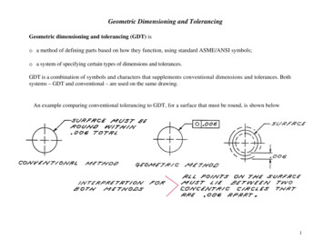
2. Robustness–How close is the concept to not meeting the requirements andconstraints?3. Optimality–What is the best concept that meets the requirements and constraints?For an aircraft designer, the term concept typically refers to a layout of the majorcomponents of the aircraft, along with their relative positions and sizes [9]. Figure 1-3shows just such a layout, along with the actual experimental aircraft this concept became:(a) Concept Generated in Engineering SketchPad [8](b) X-48C blended wing body experimental aircraft [10]Figure 1-3: Aircraft concept and experimental airplaneTo generate a concept such as the one in Figure 1-3, a large number of design variables hadto be considered, traded and eventually finalized. This set of design variables is frequentlyreferred to as the design space for the aircraft concept. Choosing the variables that willmake up the design space is often one of the most crucial steps in conceptual design. Apoor selection may lead to an intractable optimization problem, while a good selection willcapture the features important to the design and create clarity in how the design movesthrough the design space. Parameters for defining the geometry generally comprise themajority of the space, but performance parameters such as the range of the aircraft, thecruise altitude, or maximum velocity, are also often included as a part of the design space.A general design space could have thousands of dimensions and be infinitely large, butselection of the final concept is governed by three sets of criteria: constraints, objectivesand requirements.18
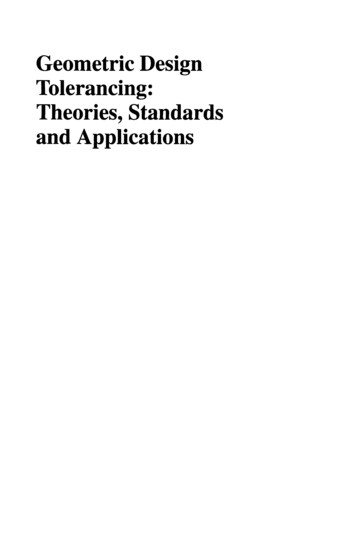
Constraints are typically bounds imposed by physics on the design space, for example, themaximum stress in a material cannot be exceeded. A constraint is often treated as a hardcutoff for the design, and is frequently given considerable margin, since exceeding aphysical constraint can sometimes have catastrophic consequences.Objectives are measures of the value or cost of the aircraft, for example, the range theaircraft can fly or the time it takes to manufacture the airplane in the factory. When takentogether, these objectives often form an objective function which will be maximized orminimized by selecting the correct concept in the design space.Requirements are the genesis of an aircraft program, typically a list of tasks the aircraftshould perform and specifications to which the aircraft is expected to conform. In this way,requirements are a superset of the objectives, with the important distinction thatrequirements are bounded, while objectives are unbounded. Due to this bounding, systemlevel requirements flow down into secondary subsystem requirements. In practice,requirements are essentially treated as constraints in the design problem, however unlikephysical constraints, requirements are often flexible and iterated on between the designerand the customer. This negotiation ensures maximum value is obtained from the newaircraft concept.The role of the concept is to link together the requirements, constraints and objectives, asshown in Figure 1-4 below.19
Figure 1-4: Aircraft concept linking requirements, constraints and objectives [2] (Adaptedfrom [3])Searching a design space is often a daunting task, and the conceptual designer’s tool ofchoice is the trade study. During a trade study, the designer will take a subset of designvariables, sweep over the range between some minimum and maximum value, and studythe corresponding values of the objectives. This process allows the designer to see howchanges in the design variables affect the performance of a concept, providing insight intothe best selections for the design variables, along with the sensitivity of the performance ofthe concept to these selections.Trade studies have traditionally been performed using empirical or historical methods suchas those compiled by Raymer [11], Torenbeek [5], Roskam [12], Shevell [13], Schaufele [14]and Anderson [9], however, advances in high performance computing have altered thelandscape in a few ways. First, integrated design tools have enabled trade studies to explorelarger design spaces by merging design variables from multiple areas of aircraft design.These tools have relied extensively on the development of Multidisciplinary Analysis andOptimization (MDAO), which will be discussed in Chapter 2. Additionally, physics basedanalysis methods, which had typically reserved for preliminary and detailed design, have20
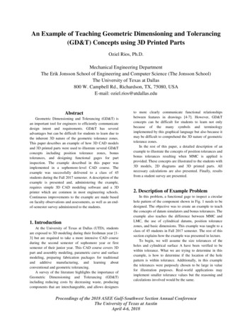
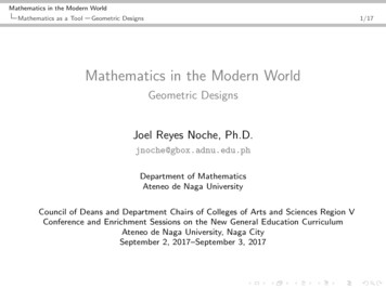
become available for use in conceptual design. Physics based methods in particular haveopened conceptual design to concepts for which no historical or empirical data exists,leading to exciting advances such as the D8 [15] and the blended wing body [16].1.3Trend of Increasing Design TimeDespite the role integrated tools and physics based models have played in conceptualdesign, perhaps the most significant advance in recent years has been the implementationof numerical optimization, enabled by advances in computing technology. Optimization canbe used to save the designer time and effort by intelligently searching the space of designvariables for the concept which maximizes the objective function, ensuring feasibility,robustness, and optimality.Numerical optimization has become standard in all aspects of the design community. Toolssuch as PASS [17], WingMOD [18], SUAVE [19], CEASIOM [20], and TASOPT [21] arejust a few examples of tools which have achieved recognition in the aircraft designcommunity. However, despite advances in numerical optimization and increases incomputational speed, there is an alarming upward trend in development time for modernaircraft, as shown by Figure 1-5:21
Contrasted with other 0/16Distribution Statement “A” (Approved for Public Release, Distribution Unlimited)4Figure 1-5: Increasing development time of modern aircraft [4]Simply put, the proliferation of high performance computing does not seem to haveresulted in the more rapid development of aircraft. This increasing trend has no singlecause and is by no means easy to diagnose, but one major takeaway from this trend is thatcomputational tools must be made as efficient as possible. At time of writing, many toolsstill can take hours, and in extreme cases weeks or months to run. Thus, the pursuit ofefficiency has led to numerous proposals for algorithms, architectures and methods thatmake the process simpler and more effective. This pursuit is the main goal of the field ofMultidisciplinary Analysis and Optimization (MDAO).22
Chapter 2MDAO in Aircraft Design2.1OverviewMultidisciplinary Analysis and Optimization (MDAO)1 is an active field of researchfocused on the design and optimization of complex systems. Complex system designproblems are typically separated into multiple disciplines, or smaller sub-problems, forteams or individuals to address. Individual disciplines have historically been analyzed inisolation, with system level interactions being handled on a case by case basis or via somehierarchy. However, as high performance computation has become more widely available,design teams have been able to consider multiple disciplines simultaneously, giving rise tothe field of MDAO. The earliest examples of MDAO came out of attempts to performcoupled aerostructural optimization [22], but it has evolved into a large and diverse field.In this chapter, we will discuss key concepts in MDAO, namely the definition of adiscipline, the role of analysis, and methods of optimization.1MDAO is alternatively known as Multidisciplinary Design Optimization (MDO) or simply Multidisciplinary Optimization (MDO)23
2.2Definition of a DisciplineFull scale piloted aircraft can be incredibly complex machines: millions of parts,functioning together in unison. As such, there is no feasible way for a single individual orteam to keep track of each detail associated with the airplane. While there are manydifferent ways of decomposing complex systems, two of the most prevalent are physicaldecomposition and functional decomposition (Figure 2-1).(a) Physical Decomposition(b) Functional DecompositionFigure 2-1: Methods for system decompositionIn a physical decomposition2 , components of the aircraft are separated according to theirphysical location. In contrast, a functional decomposition separates specific tasks on theaircraft and includes all components which address this task. For most aircraft, a functionaldecomposition is used for the high level systems problem, but physical decompositions tendto be used within functional groups. A functional decomposition also makes the most sensefrom a project management standpoint, as it is most likely that a subject matter expert inone area will likely be able to apply his or her knowledge to the entire aircraft. One notableexception is aircraft engines, which are typically designed and manufactured by separatecompanies and then mounted by the airframing company. A functional decomposition leadsto the predominant disciplines (or sub tasks) in aircraft design: Aerodynamics, Weightsand Structures, Propulsion, Stability and Control, and Performance and Mission Analysis.While the exact roles of discipline teams can vary widely between organizations, a generalbreakdown with high level goals and objectives is provided here for the reader. Anexperienced professional in aircraft design may skip to Section 2.3 without loss of2alternatively a component decomposition24
continuity.2.2.1Performance and Mission AnalysisThe goal of the performance discipline is to compute how well an aircraft performs in themeasures defined by the objectives. In this way, performance is the “hub” that ties all ofthe other disciplines together. Traditionally, the core of the performance discipline hasfocused on mission analysis, captured best by the Breguet Range Equation3 : V LWiR lnSF C DWi 1(2.1)which relates several of the major variables of interest. It is immediately apparent how thedisciplines tie together:VLDfrom aerodynamics, SF C from propulsion, andWiWi 1fromweights.While the Breguet Range Equation is incredibly useful for initial sizing, other metrics ofclassical performance are also of interest, such as takeoff and landing distances, climbperformance, and trim. These metrics require a more detailed analysis, leading to a simplemission simulation where the aircraft is treated as a rigid body and simulated over a 2Dmission profile, requiring additional data from aerodynamics and propulsion. These higherfidelity calculations enable predictions for those parameters of interest that cannot becaptured in the Breguet Range Equation. Eventually, full 6 DOF simulations can bedeveloped using these same principles.While the focus of the performance discipline has historically been on mission analysis,many aircraft programs are interested in performance metrics beyond flight profiles.Performance metrics such as noise, emissions, observability, maintenance, and3Provided here for jet powered aircraft25
manufacturing have become increasingly critical for a wide variety of aircraft programs andwill likely receive increased attention in coming years.2.2.2AerodynamicsThe aerodynamics discipline is primarily concerned with how the aircraft interacts with thefluid it is traveling through. From the Breguet Range Equation, it is apparent that themain role of the aerodynamics discipline is determining the bestVLDfor the aircraft at bothnominal and off nominal flight states. However, a secondary objective is to determine thestability and control derivatives over a wide range of flight states. This aero database isnecessary for determining control surface effectiveness, trim states, and controllability of theaircraft and typically involves extensive crossover with the Stability and Control discipline.2.2.3PropulsionThe propulsion discipline is responsible for all analyses pertaining to the engine. Thepropulsion discipline must provide an estimate of thrust specific fuel consumption, SF C,which is the weight of fuel consumed per unit of thrust generated in a unit of time. Whenconsidering the mission simulation approach to performance, the broader and more usefulgoal becomes providing engine maps: curves of engine SF C and thrust as a function ofthrottle setting (or sometimes spool speed), flight speed and altitude.2.2.4Weights and StructuresThe weights and structures discipline spans all analyses concerning the prediction of theaircraft weight and design of the detailed structural layout. In conceptual design, it is morecommon to think of this discipline as weight prediction, rather than detailed structures26
design, which becomes more prevalent in preliminary and detailed design. While emptyweight prediction occupies much of the attention of the weights discipline, an equally vitaltask is predicting the location of the center of gravity for the aircraft under a variety ofloading cases. This CG excursion analysis is crucial for determining both the aerodynamicstability derivatives and the trim state the airplane, which can significantly impactperformance.2.2.5Stability and ControlThe stability and control (S&C) group is primarily responsible for sizing the aircraftempennange and control surfaces, working in conjunction with the aerodynamics group.An additional function of the S&C group is to provide the first high level control schemethat will eventually be perfected in a flight control system during the detailed designprocess. This responsibility includes sizing control actuators, along with predictingdynamic performance of the aircraft, and performing eigenmode analysis.2.3AnalysisAs was alluded to in the discussion of each of the disciplines, a discipline will typicallyreceive a set of inputs from the system problem and then provide a set of outputs back.The mathematical mapping from inputs to outputs is referred to as analysis. The field ofanalysis is exceedingly complex, having multiple levels and requiring advancedunderstanding of the discipline in question. In addition, the analysis step is the mostexpensive step by far in terms of cost, manpower and time.27
2.3.1Notion of FidelityEach discipline group in aircraft design has a number of tools at their disposal. Forexample, an aerodynamics team might have a wide variety of analytical and testing optionsincluding basic aerodynamic analysis, various computational methods, or flight testing.Any one of these options will produce the required data (or outputs to the systemsprob
A.2 Case 1: Hoburg Constraint Implemented as a Geometric Program . . . . . . 93 A.3 Case 2: Hoburg Constraint Implemented as a Sequential Geometric Program 103 9. 10. List of Figures . "A beautiful aircraft is the expression of the genius of a great engineer who is also a great artist. But it is impossible for that man to carry out the .