Transcription
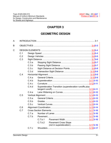
Topic # 625-000-015Manual of Uniform Minimum Standardsfor Design, Construction and Maintenancefor Streets and HighwaysDRAFT May - 2012007Printed 2/73/4/20110CHAPTER 3GEOMETRIC DESIGNAINTRODUCTION . 3-1BOBJECTIVES . 3-43-3CDESIGN ELEMENTS . 3-53-4C.1Design Speed . 3-53-4C.2Design Vehicles . 3-63-5C.3Sight Distance . 3-73-6C.3.aStopping Sight Distance . 3-83-7C.3.bPassing Sight Distance . 3-83-7C.3.cSight Distance at Decision Points . 3-93-8C.3.dIntersection Sight Distance . 3-103-9C.4Horizontal Alignment . 3-103-9C.4.aGeneral Criteria. 3-103-9C.4.bSuperelevation . 3-113-10C.4.cCurvature . 3-123-11C.4.dSuperelevation Transition (superelevation runoffs plustangent runoff). 3-133-11C.4.eLane Widening on Curves . 3-133-12C.5Vertical Alignment . 3-143-13C.5.aGeneral Criteria. 3-143-13C.5.bGrades . 3-143-13C.5.cVertical Curves. 3-153-14C.6Alignment Coordination . 3-153-14C.7Cross Section Elements . 3-173-16C.7.aNumber of Lanes . 3-173-16C.7.bPavement . 3-173-16C.7.b.1Pavement Width . 3-173-16C.7.b.2Pavement Cross Slope(not in superelevation) . 3-173-16C.7.cShoulders . 3-183-17Geometric Design3-i
Topic # 625-000-015Manual of Uniform Minimum Standardsfor Design, Construction and Maintenancefor Streets and HighwaysC.8Geometric DesignDRAFT May - 2012007Printed 2/73/4/20110C.7.c.1Shoulder Width . 3-183-17C.7.c.2Shoulder Cross Slope . 3-193-18C.7.dSidewalks . 3-193-18C.7.eMedians . 3-203-19C.7.e.1Type of Median. 3-223-20C.7.e.2Median Width . 3-233-21C.7.e.3Median Slopes. 3-233-21C.7.e.4Median Barriers . 3-243-22C.7.fRoadside Clear Zone . 3-253-23C.7.f.1Roadside Clear Zone Width . 3-263-243-243-23C.7.f.2Roadside Slopes . 3-273-253-253-24C.7.f.3Criteria for Guardrail . 3-273-253-253-24C.7.gCurbs .3-293-273-273-25C.7.hParking . 3-293-273-273-25C.7.iRight of Way . 3-293-273-273-25C.7.jChanges in Typical Section. 3-313-293-293-27C.7.j.1General Criteria . 3-313-293-293-27C.7.j.2Lane Deletions and Additions . 3-313-293-293-27C.7.j.3Special Use Lanes . 3-313-293-293-27C.7.j.4Structures . 3-323-293-293-27C.7.j.4.(a)Horizontal Clearance3-333-303-303-28C.7.j.4.(b)Vertical Clearance3-333-303-303-28C.7.j.4.(c)End Treatment . 3-333-303-303-28Access Control . 3-343-313-313-29C.8.aJustification . 3-343-313-313-29C.8.bGeneral Criteria. 3-343-313-313-29C.8.b.1Location of Access Points . 3-343-313-313-29C.8.b.2Spacing of Access Points . 3-353-313-313-29C.8.b.3Restrictions of Maneuvers . 3-353-323-323-30C.8.b.4Turn Lanes . 3-353-323-323-30C.8.b.5Grade Separation . 3-363-333-333-31C.8.b.6Roundabouts . 3-363-333-333-31C.8.cControl for All Limited Access Highways . 3-373-333-333-31C.8.dControl of Urban Streets . 3-373-343-343-323-ii
Topic # 625-000-015Manual of Uniform Minimum Standardsfor Design, Construction and Maintenancefor Streets and HighwaysC.9Geometric DesignDRAFT May - 2012007Printed 2/73/4/20110C.8.eControl for Rural Highways . 3-383-353-353-33C.8.fLand Development . 3-383-353-353-33Intersection Design . 3-393-363-363-34C.9.aGeneral Criteria. 3-393-363-363-34C.9.bSight Distance . 3-403-373-373-35C.9.b.1General Criteria . 3-413-383-383-36C.9.b.2Obstructions to Sight Distance . 3-423-393-393-37C.9.b.3Stopping Sight Distance . 3-433-403-403-38C.9.b.3.(a)Approach to Stops3-433-403-403-38C.9.b.3.(b)On Turning Roads3-433-403-403-38C.9.b.4Sight Distance for Intersection Maneuvers3-433-403-403-38C.9.b.4.(a)Driver’s Eye Position andVehicle Stopping Position3-453-423-423-40C.9.b.4.(b)Design Vehicle . 3-463-433-433-41C.9.b.4.(c)Case B1 - Left Turns Fromthe Minor Road. 3-463-433-433-41C.9.b.4.(d)Case B2 - Right Turns Fromthe Minor Road and Case B3 –Crossing Maneuver From theMinor Road . 3-473-443-443-42C.9.b.4.(e)Intersections with Traffic SignalControl (AASHTO Case D)3-473-443-443-42C.9.b.4.(f)Intersections with All-Way StopControl (AASHTO Case E)3-483-453-453-43C.9.b.4.(g)Left Turns from the Major Road(AASHTO Case F)3-483-453-453-43C.9.b.4.(h)Intersection Sight DistanceReferences . 3-483-453-453-43C.9.cAuxiliary Lanes . 3-493-463-463-44C.9.c.1Merging Maneuvers. 3-493-463-463-44C.9.c.2Acceleration Lanes . 3-493-463-463-44C.9.c.3Exit Lanes. 3-503-473-473-45C.9.dTurning Roadways at Intersections . 3-513-483-483-46C.9.d.1Design Speed . 3-523-483-483-46C.9.d.2Horizontal Alignment . 3-523-493-493-47C.9.d.3Vertical Alignment . 3-523-493-493-473-iii
Topic # 625-000-015Manual of Uniform Minimum Standardsfor Design, Construction and Maintenancefor Streets and HighwaysC.10C.11C.12Geometric DesignDRAFT May - 2012007Printed 2/73/4/20110C.9.d.4Cross Section Elements . 3-533-493-493-47C.9.eAt Grade Intersections . 3-533-503-503-48C.9.e.1Turning Radii . 3-533-503-503-48C.9.e.2Cross Section Correlation . 3-543-513-513-49C.9.e.3Median Openings . 3-543-513-513-49C.9.e.4Channelization. 3-553-523-523-50C.9.fDriveways . 3-553-523-523-50C.9.gInterchanges . 3-563-523-523-50C.9.hClear Zone . 3-573-543-543-52Other Design Factors . 3-573-543-543-52C.10.aPedestrian Facilities . 3-573-543-543-52C.10.a.1 Policy and Objectives - New Facilities3-583-553-553-53C.10.a.2 Accessibility Requirements. 3-583-553-553-53C.10.a.3 Sidewalks . 3-583-553-553-53C.10.a.4 Curb Ramps . 3-593-563-563-54C.10.a.5 Additional Considerations . 3-603-573-573-55C.10.bBicycle Facilities . 3-603-573-573-55C.10.cBridge Design Loadings . 3-603-573-573-55C.10.dDead End Streets and Cul-de-sacs . 3-613-573-573-55C.10.eBus Benches and Transit Shelters . 3-613-583-583-56C.10.fTraffic Calming . 3-613-583-583-56Reconstruction . 3-613-583-583-56C.11.aIntroduction . 3-613-583-583-56C.11.bEvaluation of Streets and Highways . 3-623-593-593-57C.11.cPriorities . 3-623-593-593-57Design Exceptions . 3-653-623-623-603-iv
Topic # 625-000-015Manual of Uniform Minimum Standardsfor Design, Construction and Maintenancefor Streets and HighwaysDRAFT May - 2012007Printed 2/73/4/20110TABLESTABLE 3–1TABLE 3–2TABLE 3–3TABLE 3–3TABLE 3–3TABLE 3–4TABLE 3–5TABLE 3–6TABLE 3–7TABLE 3–8TABLE 3–9TABLE 3–10TABLE 3–11TABLE 3–12TABLE 3–13TABLE 3–14TABLE 3–15TABLE 3–16TABLE 3–17TABLE 3–18TABLE 3–19TABLE 3–20ATABLE 3–20BGeometric DesignRECOMMENDED MINIMUM DESIGN SPEED (MPH)3-663-633-633-61DESIGN VEHICLES . 3-673-643-643-62HORIZONTAL CURVATURE . 3-683-653-653-63HORIZONTAL CURVATURE (Continued) . 3-693-663-663-64HORIZONTAL CURVATURE (Continued) . 3-693-663-663-64RECOMMENDED MAXIMUM GRADES IN PERCENT3-703-673-673-65MAXIMUM CHANGE IN GRADE WITHOUT USING VERTICALCURVE .3-703-673-673-65SIGHT DISTANCES AND LENGTHS OF VERTICAL CURVES3-713-683-683-66MINIMUM LANE WIDTHS . 3-733-693-693-67MINIMUM WIDTHS OF PAVEMENT AND SHOULDERS FORTWO (2) LANE RURAL HIGHWAYS . 3-733-693-693-67SHOULDER WIDTHS FOR MULTILANE RURAL DIVIDEDHIGHWAYS .3-733-693-693-67MEDIAN WIDTH FOR FREEWAYS (URBAN AND RURAL)3-743-703-703-68MEDIAN WIDTH FOR RURAL HIGHWAYS(MULTILANE FACILITIES) . 3-743-703-703-68MINIMUM WIDTH OF CLEAR ZONE . 3-753-713-713-69ACCESS CONTROL FOR ALL LIMITED ACCESS HIGHWAYS3-763-723-723-70SIGHT DISTANCE FOR APPROACH TO STOPS . 3-773-733-733-70LENGTH OF TAPER FOR USE IN CONDITIONS WITH FULLWIDTH SPEED CHANGE LANES. 3-773-733-733-70DESIGN LENGTHS OF SPEED CHANGE LANES FLATGRADES - 2 PERCENT OR LESS. 3-783-743-743-71RATIO OF LENGTH OF SPEED CHANGE LANE ON GRADETO LENGTH ON LEVEL .3-793-753-753-72MINIMUM DECELERATION LENGTHS FOR EXIT TERMINALS3-803-763-763-73MINIMUM ACCELERATION LENGTHS FOR ENTRANCETERMINALS . 3-813-773-773-74CALCULATED AND DESIGN VALUES FOR TRAVELED WAYWIDENING ON OPEN HIGHWAY CURVES (TWO-LANEHIGHWAYS, ONE-WAY OR TWO-WAY). 3-823-783-783-75ADJUSTMENTS FOR TRAVELED WAY WIDENING VALUES ONOPEN HIGHWAY CURVES (TWO-LANE HIGHWAYS, ONE-WAYOR TWO-WAY) . 3-833-793-793-763-v
Topic # 625-000-015Manual of Uniform Minimum Standardsfor Design, Construction and Maintenancefor Streets and HighwaysTABLE 3–21TABLE 3–22TABLE 3–23TABLE 3–24DRAFT May - 2012007Printed 2/73/4/20110DESIGN WIDTHS OF PAVEMENTS FOR TURNINGROADWAYS . 3-843-803-803-77SUPERELEVATION RATES FOR CURVES ATINTERSECTIONS . 3-853-813-813-78MAXIMUM RATE OF CHANGE IN PAVEMENT EDGEELEVATION FOR CURVES AT INTERSECTIONS . 3-853-813-813-78MAXIMUM ALGEBRAIC DIFFERENCE IN PAVEMENT CROSSSLOPE AT TURNING ROADWAY TERMINALS . 3-853-813-813-78FIGURESFIGURE 3–1FIGURE 3–2FIGURE 3–2AFIGURE 3–3FIGURE 3–4FIGURE 3–5FIGURE 3–6FIGURE 3–7FIGURE 3–8FIGURE 3–9FIGURE 3–10FIGURE 3–11FIGURE 3–12FIGURE 3–13Geometric DesignRURAL HIGHWAYS, URBAN FREEWAYS AND HIGH SPEEDURBAN ARTERIALS . 3-863-823-823-79URBAN HIGHWAYS AND HIGH SPEED URBAN STREETS3-873-833-833-80SIGHT DISTANCE ON CURVES . 3-883-843-843-81CRITICAL LENGTH VERSUS UPGRADE . 3-893-853-853-82LENGTH OF CREST VERTICAL CURVE(Stopping Sight Distance) . 3-903-863-863-83LENGTH OF CREST VERTICAL CURVE(Passing Sight Distance) . 3-913-873-873-84LENGTH OF SAG VERTICAL CURVE(Headlight Sight Distance) . 3-923-883-883-85SIGHT DISTANCES FOR APPROACH TO STOP ON GRADES3-933-893-893-86DEPARTURE SIGHT TRIANGLE TRAFFIC APPROACHINGFROM LEFT OR RIGHT. 3-943-903-903-87INTERSECTION SIGHT DISTANCE . 3-953-913-913-88SIGHT DISTANCE FOR VEHICLE TURNING LEFT FROMMAJOR ROAD . 3-963-923-923-89TERMINATION OF MERGING LANES . 3-973-933-933-90ENTRANCE FOR DECELERATION LANE . 3-983-943-943-91TYPICAL STORAGE LANE . 3-993-953-953-923-vi
Topic # 625-000-015Manual of Uniform Minimum Standardsfor Design, Construction and Maintenancefor Streets and HighwaysDRAFT May - 2012007Printed 2/73/4/20110CHAPTER 3GEOMETRIC DESIGNAINTRODUCTION{General Comments:1. Chapter could be reorganized.a. Could break out (or group) Design Controls into a separate section (or chapter?)b. Move figures and tables into appropriate sections.c. Grouping of similar topics (i.e., sidewalk criteria, horizontal clearance criteria )2. Address minimum standards/criteria for RRR type projects.3. Update Horizontal Clearance / Clear Zone.4. .}Geometric design is defined as the design or proportioning of the visible elements of thestreet or highway. The geometry of the roadway is of central importance since it providesthe framework for the design of other highway elements. In addition, the geometric designestablishes the basic nature and quality of the vehicle path, which has a primary effectupon the overall safety characteristics of the street or highway.The design of roadway geometry must be conducted in close coordination with other designelements. These other elements include: pavement design, roadway lighting, traffic controldevices, transit, drainage, and structural design. The design should consider safe roadsideclear zones, bicycle and pedestrian safetyaccommodation, emergency response, andmaintenance capabilities.The safety characteristics of the design should be given primary consideration. The initialestablishment of sufficient right of way and adequate horizontal and vertical alignment isnot only essential from a safety standpoint, but also necessary to allow future upgradingand expansion without exorbitant expenditure of highway funds.The design elements selected should be reasonably uniform but should not be inflexible.More relaxed minimum standard may apply for Traditional Neighborhood Designs. – seeChapter 19. Chapter 19 is intended for use for conditions that encourage pedestrians andbicycles for mixed use development. For this type development, truck traffic should belimited to deliveries within the development with no through truck traffic. Some laneGeometric Design3-1A
Topic # 625-000-015Manual of Uniform Minimum Standardsfor Design, Construction and Maintenancefor Streets and HighwaysDRAFT May - 2012007Printed 2/73/4/20110encroachment will be expected during those required deliveries. Transit service will beprovided on the perimeter of the development and not penetrate the development.The minimum standards presented in this chapter should not automatically become thestandards for geometric design. The designer should consider use of a higher level, whenpractical, and consider cost-benefits as well as consistency with adjacent facilities.Reconstruction and maintenance of facilities should, where practical, include upgrading tothese minimum standards.[RQ1]In restricted or unusual conditions, it may not be possible to meet the minimum standards.In such cases, the designer must obtain an exception in accordance with CHAPTER 14 –DESIGN EXCEPTIONS from the reviewing or permitting organization. However, everyeffort should be made to obtain the best possible alignment, grade, sight distance, andproper drainage consistent with the terrain, the development, safety, and fund availability.The concept of highway users has expanded in recent years creating additional concernsfor the designer.In making decisions on the standards to be applied to a particular project, the designermust also now address the needs of pedestrians, transit, bicyclists, elder road users[RQ2],the disabled, and other users. This is true for both urban and rural facilities.The design features of urban local streets are governed by practical limitations to a greaterextent than those of similar roads in rural areas. The two dominant design controls are: (1)the type and extent of urban development and its limitations on rights of way and (2) zoningor regulatory restrictions. Some streets primarily are land service streets in residentialareas. In such cases, the overriding consideration is to foster a safe and pleasingenvironment. Other streets are land service only in part, and features of traffic and publictransit service may be predominant.The selection of the type and exact design details of a particular roadway or highwayrequires considerable study and thought. When reference is made to guidelines anddesign details given by current American Association of State Highway and TransportationOfficials (AASHTO) publications, these guidelines and standards should generally beconsidered as minimum criteria. For the design of recreational roads, local service roads,and alleys, see AASHTO publications.Right of way and pavement width requirements[RQ3] for new construction may be reducedGeometric Design3-2
Topic # 625-000-015Manual of Uniform Minimum Standardsfor Design, Construction and Maintenancefor Streets and HighwaysDRAFT May - 2012007Printed 2/73/4/20110for the paving of certain existing unpaved subdivision streets and low volume rural roadsprovided all of the conditions listed below are satisfied: The road is functionally classified as a local road. The 20-year projected ADT is less than 750 vehicles per day and the design yearprojected peak hourly volume is 100 vehicles per hour or less. Note: The designyear may be any time within a range of the present to 20 years in the future,depending on the nature of the improvement. The road has no foreseeable probability of changing to a higher functionalclassification through changes in land use, extensions to serve new developing landareas, or any other use which would generate daily or hourly traffic volumes greaterthan those listed above. There is no reasonable possibility of acquiring additional right of way without: Incurring expenditures of public funds in an amount which would beexcessive compared to the public benefits achieved Causing substantial damage or disruption to abutting property improvementsto a degree that is unacceptable considering the local environmentGeometric Design3-3
Topic # 625-000-015Manual of Uniform Minimum Standardsfor Design, Construction and Maintenancefor Streets and HighwaysBDRAFT May - 2012007Printed 2/73/4/20110OBJECTIVESThe major objective in geometric design is to establish a vehicle path and environmentproviding a reasonable margin of safetyaccommodation for the motorist, transit, bicyclist,and pedestrian under the expected operating conditions and speed. It is recognized thatFlorida's design driver is aging and tourism is our major industry. This gives even moreemphasis to focus on simplicity and easily understood geometry and roadway features.The achievement of this objective may be realized by meeting certain specific objectives,which include the following: Provide the most simple geometry attainable, consistent with the physicalconstraints Provide a design that has a reasonable andsafetyaccommodation at the expected operating speed Provide a design that is safe atwith consideration for night and under adverseweather conditions Provide a facility that is adequate for the expected traffic conditions and pedestrian,bicyclist and transit needs Provide a design that reasonably accommodates a variety of drivercharacteristicsAllow for reasonable deficiencies in the driver, such as: Periodic inattention Reduced skill and judgment Slow reaction and responseconsistentmarginofProvide an environment that minimizes hazards, is as hazard free as practical, andis "forgiving" to a vehicle that has deviated from the travel path or is out of control.Geometric Design3-4
Topic # 625-000-015Manual of Uniform Minimum Standardsfor Design, Construction and Maintenancefor Streets and HighwaysCDRAFT May - 2012007Printed 2/73/4/20110DESIGN ELEMENTSC.1Design SpeedThe design speed is defined as a selected rate of travel used to determine thevarious geometric features of the roadway. The basic purpose in selection of ausing the design speed concept is to achieve consistency in the various designelements that influence vehicle operations. Since many critical design features(e.g., sight distance and curvature) are predicated upon design speed, the selectionof the proper value is essential to allow for the safe design of a safe street orhighway.The selection of an appropriate design speed is dependent on the predicted driverbehavior and is, therefore, rather complex. This selection of design speed shouldreceive considerable preliminary investigation and thought so safety will be realizedfrom the design.The primary basis for selecting the design speed should be a rational prediction ofthe probable maximum operating speed (by approximately 90 percent of thevehicles) on the street or highway. The "average running speed" is not acceptableas a design speed.In selecting design speeds, consideration should also be given to pedestrians andbicycle usage and to the present and future adjacent land use.Recommended minimum values for design speed are given in Table 3 - 1. Thesevalues should be considered as general guidelines only. The maximum normaloperating speed is dependent on many variables including: Topography General roadway geometry Surrounding Adjacent land use Degree of aAccess Management Frequency of traffic signals or other traffic control devices Posted speed limit and the degree of enforcementGeometric Design3-5
Topic # 625-000-015Manual of Uniform Minimum Standardsfor Design, Construction and Maintenancefor Streets and HighwaysDRAFT May - 2012007Printed 2/73/4/20110The driver does not necessarily adjust speed to the classification of importance (orlack of it) of the street or highway.The design speed shall not be less than the expected posted or legal speed limit. Adesign speed 5 mph to 10 mph greater than the posted speed limit will compensatefor a slight overrunning of the speed limit by some drivers.The use of the higher design speed (no speed restrictions) given in Table 3 - 1 isrecommended for the following situations: Topography allowing or encouraging higher operating speeds Roadway geometry permitting high speeds Long uninterrupted sections of roadwayThe design speed utilized should be consistent over a given section of highway.Required changes in design speed should be effected in a gradual fashion. Whenisolated reductions in design speed cannot reasonably be avoided, appropriatespeed signs should be posted.{Move Table Here}C.2Design VehiclesA "design vehicle" is a selected motor vehicle whose weight, dimensions, andoperating characteristics are used to establish highway design controls toaccommodate vehicles of a designated type. For the purpose of geometric design,the design vehicle should be one with dimensions and minimum turning radii largerthan those of almost all vehicles in its class. Design vehicles are listed in Table 3 - 2.One or more of these vehicles should be used as a control in the selection ofgeometric design elements. In certain industrial (or other) areas, special servicevehicles may have to be considered in the design. Fire equipment and emergencyvehicles should have reasonable access to all areas.If a significant number or percentage (5 percent of all the total traffic) of vehicles ofthose classes larger than passenger vehicles are likely to use a particular street orhighway, that class should be used as a design control. The design of major arterialstreets and highways should normally be adequate to accommodate all designvehicles. The decision as to which of the design vehicles (or other special vehicles)should be used as a control is complex and requires careful study. Each situationGeometric Design3-6
Topic # 625-000-015Manual of Uniform Minimum Standardsfor Design, Construction and Maintenancefor Streets and HighwaysDRAFT May - 2012007Printed 2/73/4/20110must be evaluated individually to arrive at a reasonable estimate of the type andvolume of expected traffic. {Reference to AASHTO for more info on DesignVehicles.} Design criteria significantly affected by the type of vehicle include: Horizontal and vertical clearances Alignment Lane widening on curves Shoulder width requirements Turning roadway and intersection radii Intersection sight distance Acceleration criteriaParticular care should be taken in establishing the radii at intersections, so vehiclesmay enter the street or highway without encroaching on adjacent travel lanes orleaving the pavement. It is acceptable for occasional trucks or buses to make use ofboth receiving lanes, especially on side streets.C.3Sight DistanceThe provision for adequate horizontal and vertical sight distance is an essentialfactor in the development of a safe street or highway. An unobstructed view of theupcoming roadway is necessary to allow time and space for the safe execution ofpassing, stopping, intersection movements, and other normal and emergencymaneuvers. It is also important to provide as great a sight distance as possible toallow the driver time to plan for future actions. The driver is continuously required toexecute normal slowing, turning, and acceleration maneuvers. If a driverhe can planin advance for these actions, traffic flow will be smoother and less hazardous.Unexpected emergency maneuvers will also be less hazardous if they are notcombined with uncertainty regarding the required normal maneuvers. Theappropriate use of lighting (CHAPTER 6 - ROADWAY LIGHTING) may be requiredto provide adequate sight distances for night driving.Future obstruction to sight distance that may develop (e.g., vegetation) or beconstructed should be taken into consideration in the initial design. Areas outside ofthe highway right of way that are not under the highway agency's jurisdiction shouldbe considered as points of obstruction. Planned future construction of medianGeometric Design3-7
Topic # 625-000-015Manual of Uniform Minimum Standardsfor Design, Construction and Maintenancefor Streets and HighwaysDRAFT May - 2012007Printed 2/73/4/20110barriers, guardrails, grade separations, or other structures should also beconsidered as possible sight obstructions.C.3.aStopping Sight DistanceSafe stopping sight distances shall be provided continuously on all streetsand highways. The factors, which determine the minimum distance requiredto stop, include: Vehicle speed Driver's total reaction time Characteristics and conditions of the vehicle Friction capabilities between the tires and the roadway surface Vertical and horizontal alignment of the roadwayIt is desirable that the driver be given sufficient sight distance to avoid anobject or slow moving vehicle with a natural, smooth maneuver rather thanan extreme or panic reaction.The determination of available stopping sight distance shall be based on: a height of the driver's eye equal to 3.50 feet and a height of obstruction to be avoided equal to 0.50 feet.It would, of course, be desirable to use a height of obstruction equal to zero(coincident with the roadway surface) to provide the driver with a morepositive sight condition. Where horizontal sight distance may be obstructedon curves, the driver's eye and the obstruction shall be assumed to belocated at the centerline of the travel lane on the inside of the curve.The stopping sight distance shall be no less than the values given in Table3 - 6.C.3.bPassing Sight DistanceThe passing maneuver, which requires occupation of the opposing travellane, is inherently dangerous. The driver is required to make simultaneousGeometric Design3-8
Topic # 625-000-015Manual of Uniform Minimum Standardsfor Design, Construction and Maintenancefor Streets and HighwaysDRAFT May - 2012007Printed 2/73/4/20110estimates of time, distance, relati
for Design, Construction and Maintenance for Streets and Highways Geometric Design 3-i CHAPTER 3 GEOMETRIC DESIGN . TABLE 3–16 DESIGN LENGTHS OF SPEED CHANGE LANES F

