Transcription
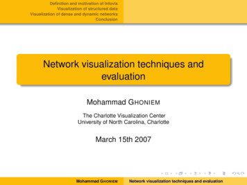
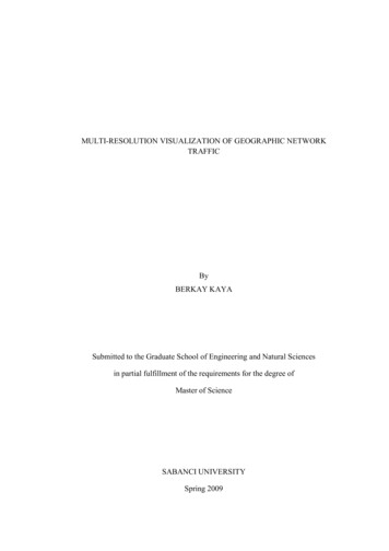
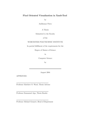
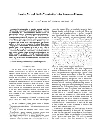
2018 Building Performance Analysis Conference andSimBuild co-organized by ASHRAE and IBPSA-USAChicago, ILSeptember 26-28, 2018Visualization of CFD Simulation Results in VR Environment for Design FeedbackCharles S. Sanchez, PhD and Zhang Xiaoqin, PhDEnergy Research Institute @ NTUABSTRACTIn the tropics, where air-conditioning consumes around50% of the electricity, natural ventilation is a primarypassive design strategy. Due the complexity of naturalwind flow, Computational Fluid Dynamics (CFD)simulations are used to evaluate the efficiency of appliednatural ventilation, however, architects and designersfind it difficult to visualize the results provided by thesesimulations, something that can be improved with theuse of better visualization tools. This research projectuses a BIM created unit as a case study for CFDsimulation of natural ventilation displayed in a VRenvironment, in order to improve design feedback andthe visualization of simulation data for naturalventilation.Figure 1 Sketches illustrating the natural ventilationprinciples applied in architecture (CIBSE 1997).Highly dense developments such as high-rise housingand office towers in urban areas, present a challengewhen applying passive design strategies. The interactionbetween built volume and natural airflow becomes morecomplex and difficult to prognosticate by thearchitectural designer, however, technology inComputational Fluid Dynamics (CFD) simulation allowsus to understand the complexity of air movement outsideand inside of a building, and the interactions with objectsand openings that conform the architectural space.KEYWORDSComputational Fluid Dynamics (CFD), Virtual Reality(VR), Augmented Reality (AR), Passive DesignStrategies, Natural Ventilation, Building informationmodelling (BIM), Design Feedback.INTRODUCTIONWhen designing an energy efficient and sustainablebuilding, passive design strategies are the most reliableway to save energy and provide maximum comfort forthe occupants. Common practices in passive strategies inarchitecture include the evaluation of the wind’spredominant direction against the building’s orientationin order to achieve an optimal natural ventilation, this isdone by assuming that the wind will enter the room andexit through the openings. This basic assumption isbased on principles that have been tested and confirmedthough practical applications (Stavridou 2015).Figure 2 Current Professional trends and practices forCFD simulation integration in architecture design.The design stage in which the CFD simulation is createdpresents relevant aspects that will affect the complexityof the calculations and the impact of the results in thedesign output. Therefore, the importance of integratingCFD simulation studies at early stages of designallowing room for modifications to the geometry of abuilding in order to provide suitable orientation andopenings to incorporate natural ventilation andoptimized air flow. Making these changes at moreadvanced levels of design, will involve more restrictionsand a higher cost.Advances in visualization tools are instrumental in theintegration of CFD simulation and architecture design.The most common visualization tools such as346 2018 ASHRAE (www.ashrae.org) and IBPSA-USA (www.ibpsa.us).For personal use only. Additional reproduction, distribution, or transmission in either print or digital form is not permitted withoutASHRAE or IBPSA-USA's prior written permission.
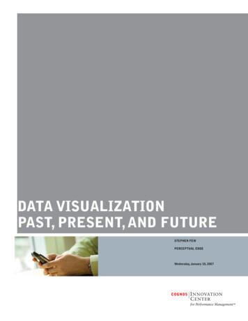
photorealistic renders and building’s walkthroughanimations, are used to display the final design to clientswho might not be familiar with the 2D language used inconstruction blueprints. In recent years Virtual andAugmented Reality (VR & AR) have done anappearance in the architecture design market as newways to display three dimensional information. Toolswith such power present great potential to display morecomplex information, beyond colors and shapes in amore involving way and based on the building’sgeometry and materials. Considering the potential ofdisplaying analytical Information in a VR and ARenvironment, a design professional can understand in amore holistic way how the simulation results interactwith the building’s geometry. Furthermore, visualizingcomplex CFD simulations in a VR environment can takeadvantage of the work done creating the simulationresults to extract detailed data, expose each componentof the building interacting with the simulatedinformation in different and more interactive ways. CFDsimulations are pretty much a field on its own,interpreting results from this type of calculationsrequires highly skilled professionals with the capacity tocreate the simulation atmosphere and proper settings. Inmany cases the complexity of the results is not fullyutilized due to interdisciplinary gaps betweenprofessionals not allowing architects and buildingdesigners to make their own conclusions and designrelated estimations due to the lack of familiarity withCFD simulations. In view of the many advantages of thetechnology in visualization, building informationmodelling and CFD simulations; and the intricatecontributions they have in the architecture designprocess; establishing a primary platform for coherentintegration of data sourced from these three platforms,represents a first step in the implementation of BIM andCFD simulation that eventually can be transmitted tomobile, web based and software integrated tools.Background and previous studiesBACKGROUND AND PREVIOUSSTUDIESThe need for better visualization tools in the computeraided design market had brought importantdevelopments in the way buildings are visualized andhow we interact with them before they are constructed.Tools such as rendered realistic images, ents; and the possibilities to navigate the spaceat a human scale level, are now commonly usedresources. Are these tools in human interaction withvirtual objects and environments, what is allowing abetter understanding of design conditions as close toreality as we have come so far (Langevin 2015).Buildings existing only in the computer as CAD files andrealistic setups are, so far, the trend in complex 3D andvirtual representation, all done with the purpose ofallowing non-design related professionals, a betteraccess to this information. For any architect or engineer,a set of blueprints in 2D is more than enough to visualizethe general and detailed aspects of a building; however,for many non-related professionals, picturing 3Dinformation from a 2D sources is represents a difficulttask. The same happens for complex data generated insimulation software when presented to a professionalwithout the proper raining in CFD data analytics. Is inthis type of scenarios where a better way to display CFDsimulation results is needed. The common practice forevaluating CFD simulation results is to “slice” volumesfilled with simulation information and present them as2D images of the simulation results (Figure 3).Figure 3 Evaluation of CFD simulation results bycreating 2D sections in horizontal and vertical planes.Previous research projects have done VR integration forCFD simulation applied in architecture, with verypositive results, creating a better understanding of theneed for such platform and awareness of its potential toinclude factors such as: positional data, scaling, timeintervals and correct-realistic perspective (Berger et al.2015). By allowing a coordinated integration of datawith the user in a 360 surrounding environment theunderstanding of the simulated data can be improved andtherefore lead to a better use in design feedback.In some studies, the focus is on the Graphic UserInterface (GUI) created also to interact with previouslycalculated simulation data and the VR space. VRplatforms have also been created to provide designfeedback for thermal simulation (Hosokawa et al. 2016),allowing changes in the HVAC system and creating newsimulation results to evaluate different possible designoptions (Fukuda et al. 2015). Additionally, in caseswhere the emphasis is the create the better informationdisplay for large and complex data, the results are goodenough to allow types of navigation that are not possiblein CFD visualization platform such as Paraview. Usingtools from the video gaming industry –most of the347 2018 ASHRAE (www.ashrae.org) and IBPSA-USA (www.ibpsa.us).For personal use only. Additional reproduction, distribution, or transmission in either print or digital form is not permitted withoutASHRAE or IBPSA-USA's prior written permission.
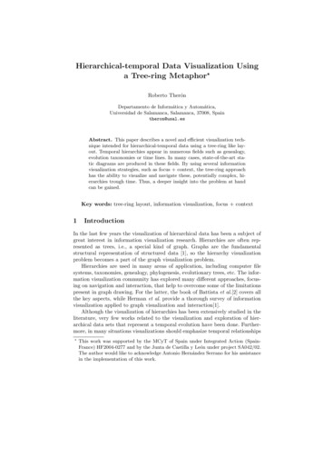
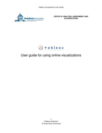
previously done research relies on the use of UNITY3Das main software for the creation of a VR platformbrings better and more controllable navigation andrealistic graphics, all in first person perspective.METHODOLOGYBearing in mind the multidisciplinary nature of thisproject, settings for the components has to be doneseparately using different software applications (Figure4).Figure 5 CFD simulation settings workflowFigure 4 Overview of content development for VRPlatformNext is a description of the three main settings:BIM based geometry and mesh for CFD simulation.The current practice of architecture design relies heavilyon BIM workflows to create the computer files on abuilding. In this project we have taken the geometry forthe CFD simulation from a BIM file created in thesoftware Revit. Since Revit geometry is not suitable torun a simulation in a CFD application and containsseveral objects that are not necessary for the meshcreation, the model was edited leaving only relevantcomponents such as walls, windows, doors and floors.An additional file conversion step was done using thesoftware Rhinoceros 5.0.CFD simulation for natural ventilationTo analyze natural ventilation around/in buildings, CFDis a widely used tool to study the flow field. The mainidea is to divide the space into small volumes/elementswith a mesh, and solve the Navier-Stokes equationnumerically on each mesh point. The two-equation k-εturbulence models is one of the commonly usednumerical methods to solve the mean velocity, pressureand temperature in the Navier-Stokes equation, it isaccurate enough for natural ventilation study. With theCFD simulation results, one can understand the airmovement, temperature and pressure distribution in thespace.Unity3D environment and VR settingsOne way of seeing the environment created in Unity isto consider it as an empty space where files from twodifferent products can coexist and interact in a flawlessway. After the simulation results are exported as FBXfiles (for visualization purposes), the file is added to theUnity project in the form of an asset, the same is donefor the 3D architecture model from Revit. The 2 files canbe scaled and positioned, using Unity’s positioning,scaling and rotation tools. The 3D mesh used for thesimulation works as a reference for coordination with thearchitectural model. After the 2 assets are coordinated,VR supporting options have to be selected in theproject’s settings. In order to enter the VR platform aHead Mounted Device (HMD) is needed, for thisexperiment an HTC’s Vive HDM was used, however theplatform is compatible with many other brands andmodels of HMD.Figure 6 VR equipment used at the Building Modellingand Simulation Lab of NTU’s ERIANSIMULATION AND EXPERIMENTATIONIn this paper, natural ventilation in a bedroom of aresidential building is taken for the case study. There isan exterior window facing North and a door in theopposite side of the room, assuming that the wind entersthe room through the window, and exits the room from348 2018 ASHRAE (www.ashrae.org) and IBPSA-USA (www.ibpsa.us).For personal use only. Additional reproduction, distribution, or transmission in either print or digital form is not permitted withoutASHRAE or IBPSA-USA's prior written permission.
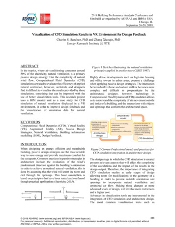
the door. Thus, the boundary condition for window is avelocity inlet, wind coming in from Northeast directionwith a speed of 1.2 m/s and the door is a pressure outlet.Flow field of the air volume in the room is of interest andheat is not considered in this simulation. Figure 6 showsthe top, front and isometric views of the room witharrows pointing the direction of the wind. Two isometricviews of the 3D mesh generated for the simulation isillustrated in Figure 7.The mesh of size 0.05m was adopted with a total numberof 213,772 elements generated for the air volume. Theresults can be presented with velocity contours andvelocity vectors on cross sections. Following the meshcreation and CFD simulation both sets of data wereadded to a Unity3D project as assets.Figure 7 Bedroom unit floor plan with diagram of winddirection (NE to SW).Figure 9 Velocity contour on the horizontal plane atthree heights from the floor levelRoom description: Common single bedroom at a residential unit inSingapore Measurements: 3.2 x 2.4 meters Area: 7.2 m2 External façade with vertical element to block Westsunlight, element length: 0.6m Predominant wind direction: Northeast A vertical element is located next to the window inorder to reduce the impact of direct sunlight in theafternoon. The same element helps capturing morewind flow into the roomFigures 10 to 13 show the same results obtained duringthe simulation, now from a human perspective in a VRenvironment, arrows represent the vectors indicating theorigin and path followed by the wind entering the roomfrom the window and moving to the corner of the roomand the side of the door.Figure 8 Mesh of the bedroom unit for CFD simulation.RESULTSFigure 8 shows the data collected from the CFDsimulation is displayed in a conventional 2D sectionedimage at different heights, this technique can be used forvertical sectioning in order to create similar images in avertical view. The highest speeds recorded happened inthe center of the room from the window to the corner andthe side of the door (up to 1.5 m/s).10111213Figures 10 to 13 Bedroom unit created in Revit andmesh generated for CFD natural ventilation simulation349 2018 ASHRAE (www.ashrae.org) and IBPSA-USA (www.ibpsa.us).For personal use only. Additional reproduction, distribution, or transmission in either print or digital form is not permitted withoutASHRAE or IBPSA-USA's prior written permission.
It is technically impossible to present the VR experienceachieved in this study using images, what is presented inthis paper is just part of the potential of using VR andadvanced visualization tools to bring a betterunderstanding of the results obtained using CFDsimulation in designs relying on passive ventilation. Fordesigners in general having a clear picture of complex airflow dynamics and interactions with the interior space ofa building brings a case by case understanding of thespecifics air movement, space and comfort. Thearchitecture example used in this study is basic and withlimited complexity, however the model proposed can beadapted to elements that are more intricate where thevisualization can make much valuable contribution. Isworth to say that the VR platform does not eliminate theneed for a 2D sectioning evaluation of the CFDsimulation results. The two methods can coexist and helpproviding understanding and data analytics. In somecases the data representation might be more illustrativeto represent the basic concepts –in this case naturalventilation- within a mode graphically developed model,like it is illustrated in Fig. 14.Figure 14, a final VR with illustrative naturalventilation arrows as it is used in architecture designThe image of the building (at design stage beforeconstruction) is integrated with arrows that illustrated theincoming airflow to the open balconies. In a moretechnical context arrows are not represented in suchgraphical way, this is a more “architectural” graphicrepresentation. However the arrows are not the result ofa conceptualized natural ventilation system, but theresult of a CFD calculations.Figure 15 and 16, a comparison of a final VR imageand the actual building. There are differences in thedesign and the final construction, however , the processwas enriched by the simulation work done.INTEGRATIONWITHDIFFERENTPLATFORMS AND FUTURE WORKThe study presented in this document is the first step ofan effort to provide a multiplatform visualization tool forCFD and simulation results for sustainable buildings. Aspart of this effort we are working to provide morepractical and responsive tools that will allow a fasterfeedback, better understanding of the complex dataprovided by simulation software in building design andbetter interdisciplinary collaboration. Following the VRvisualization platform, a series of studies are planned tointegrate similar tools to a web based platform with afirst-person realistic perspective for BIM models andCFD simulation results.This paper presents the first attempt to integrated CFDsimulation results in a systematic way, howevereventually more data can be integrated in the platformand new workflows in the design field will be proposed,among them: In-house CFD simulation for early stages ofdesign in sustainable buildingsNatural ventilation and natural light inbuildings can become a more discussed topic byrepresenting it in more visual ways for betterunderstanding of the design team and theclients.Building evaluation of applied design strategiescan be better visualized350 2018 ASHRAE (www.ashrae.org) and IBPSA-USA (www.ibpsa.us).For personal use only. Additional reproduction, distribution, or transmission in either print or digital form is not permitted withoutASHRAE or IBPSA-USA's prior written permission.
Figures 17 Potential benefits of including CFDsimulation results integration in VR & AR environmentsREFERENCESBerger, M., Cristie V. 2015. CFD post-processing inUnity3D, ICCS 2015 International Conferenceon Computational Science, Reykjavík, IcelandCIBSE Application Manual AM10.1997. Naturalventilation in non-domestic buildings, TheChartered Institution of Building ServicesEngineers, LondonFukuda T., Mori K., Imaizumi J. 2015. Integration ofCFD, VR, AR and BIM for Design Feedback ina Design Process - An Experimental Study, The33rd eCAADe Conference, At ViennaUniversity of Technology, Vienna, AustriaHosokawa M., Fukuda T., Yabuki N., Michikawa T.,Motamedi A. 2016. Integrating CFD and VRfor indoor thermal environment designfeedback, 11th International Symposium onArchitectural Interchanges in Asia(ISAIA2016), At Tohoku University, Sendai,JapanLangevin, J. 2015. Simulating the human-buildinginteraction: Development and validation of anagent-based model of office occupantbehaviors, Drexel University, Philadelphia, PA,United StatesStavridou, A.D. 2015. Breathing architecture:Conceptual architectural design based on theinvestigation into the natural ventilation ofbuildings, Aristotle University of Thessaloniki,Greece351 2018 ASHRAE (www.ashrae.org) and IBPSA-USA (www.ibpsa.us).For personal use only. Additional reproduction, distribution, or transmission in either print or digital form is not permitted withoutASHRAE or IBPSA-USA's prior written permission.
software Rhinoceros 5.0. CFD simulation for natural ventilation To analyze natural ventilation around/in buildings, CFD is a widely used tool to study the flow field. The main idea is to divide the space into small volumes/elements with a mesh, and solve the Navier-Stokes equa