Transcription
Introduction toHeat PipesJentung KuNASA/ Goddard Space Flight CenterGSFC· 2015
Outline Introduction Heat Pipe Operating Principles– Pressure Drops– Operating Temperature Functional Types of Heat Pipes Heat Pipe Operating Characteristics Heat Pipe Design and Selection– Designg Considerations (mostly(y for Vendors))– Selecting Heat Pipes as Part of Thermal Control System andModeling of Heat Pipes (for Thermal Analysts) Some Practical Considerations Some Examples of Flight Applications Other Types of Heat Pipes2Introduction to Heat Pipes - Ku 2015 TFAWS
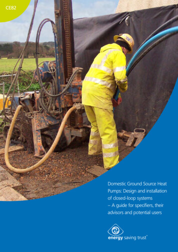
Heat Pipes - Hardware M t l (aluminum)Metal( l i) tubet b withith grooves on theth innerisurfacef– coldld extrusionti Grooves are filled with the working fluid (water, ammonia, propylene, etc.) Flanges can be added on the outer surface for easy integration with instrumentsor radiators (The flange is an integral part of the extrusion) Various diameters, lengths, and groove sizes3Introduction to Heat Pipes - Ku 2015 TFAWS
Introduction – Why Heat Pipes? Heat pipe is a capillary two-phase heat transfer device.– Transports heat from a heat source to a heat sink– Works as an isothermalizer Why two-phase thermal system?– Efficient heat transfer – boiling and condensation– Small temperature difference between the heat source andheat sink Why capillary two-phase system?– Passive – no external pumping power– SelfS lf regulatingl ti– no flowflcontrolt l devicesd i– No moving parts – vibration free4Introduction to Heat Pipes - Ku 2015 TFAWS
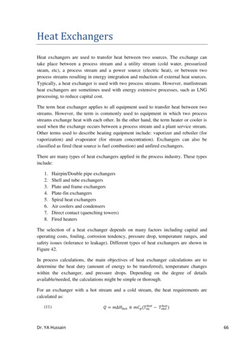
Heat Pipes – Operating PrinciplesHeat InputWickHeat OutputVapor FlowLiquid ReturnEvaporatorCondenser Typical use of heat pipe: one end (the evaporator) is attached to the heat sourcesource, and theopposite end (the condenser) to the heat sink. The middle section (the adiabatic section) isinsulated. As liquid is vaporized at the evaporator, the vapor pressure builds up, forcing vapor to flowaxiallyy alongg the center core to the condenser . Vapor condenses at the condenser. Liquid is drawn back to the evaporator by the capillary forcealong the grooves. The pressure difference between the vapor and liquid phases is sustained by the surfacetension force of the fluid. Passive – no external pumping power is required; the waste heat provides the driving force forthe fluid flow.5Introduction to Heat Pipes - Ku 2015 TFAWS
Differential Pressure Across a Curved SurfaceR1R1R2R2P1P2 P P1 - P2 (1/R1 1/R2) : Surface tension; R1 and R2: Radii of curvature6Introduction to Heat Pipes - Ku 2015 TFAWS
Pressure Differential Across a Meniscus A meniscus will be formed at the liquid/vaporinterface, and a capillary pressure is developed. R Pcap 2 cos /R : Surface tension; R: Radius of curvature; : Contact Angle The maximum capillary pressure Pcap,max 2 cos /RpR Rp RPRp : Radius of the pore7Introduction to Heat Pipes - Ku 2015 TFAWS
Pressure Balance in Heat Pipes The fluid flow will induce a frictional pressure drop.The total pressure drop over the length of the heatpipe is the sum of individual pressure drops. Ptot Pvap Pliq Pg The meniscus will curve naturally so that the capillarypressure is equal to the total pressure dropdrop.R Pcap Ptot Pcap 2 cos /R((R Rp) The flow will stop when the capillary limit is exceeded. RP Pcap,max 2 cos /RpRp : Radius of the pore For normal operation of heat pipespipes: Ptot Pcap Pcap,max8Introduction to Heat Pipes - Ku 2015 TFAWS
Pressure Differential at Liquid Vapor InterfaceLeHeat SourceLcLaHeat SinkwallLiquid FlowVapor FlowLiquid Section The vapor pressure decreases as it flows from the evaporator to the condenser. The liquid pressure decreases as it flows from the condenser to the evaporator. At any cross section of the heat pipe, a pressure differential exists between thevapor and liquid phases. This delta pressure is sustained by the surface tensionforce developed at the liquid/vapor interface at the tip of each groove. The lowest delta pressure occurs at the very end of the condenser (zero). Thehighest delta pressure occurs at the very end of the evaporator.9Introduction to Heat Pipes - Ku 2015 TFAWS
Heat Pipes - Heat Transport LimitLaLeHeat SourceLcHeat Sink For proper heat pipe operation, thetotal pressure drop must not exceedits capillary pressure head . Ptot Pcap,max Ptot Pvap Pliq Pg Pcap,max cos /Rp Heat Transport Limit– ((QL))max QmaxLeff– Leff 0.5 Le La 0.5 Lc– (QL)max measured in watt-inchesor watt-meters Capillary pressure head:wallLiquid FlowVapor FlowLiquid FlowwallEvaporatorSectionAdiabaticS eDropCapillaryPressureLiquidLi idLiquidLiquidPressureDropNo Gravity ForceAdverse Gravity ForceLeLaLc Pcap 1/ Rp Liquid pressure drop: Pliq 1/ Rp2 An optimal pore radius exists formaximum heat transport. Limited pumping head against gravityDistanceb) Vapor and liquid pressure distributions10Introduction to Heat Pipes - Ku 2015 TFAWS
Some Wicks Used in Heat Pipes Many HP hardware variationsexist.– Size– Length– Shape– Wick material– Wick constructionPOWDER METAL WITH– Working fluidPEDESTAL ARTERY Axial Grooves– Versatility– Design simplicity– Reliability– High heat transport– High thermalconductance– Broadly used inaerospace applicationsCIRCUMFERENTIALSCREEN WICKAXIAL GROOVESSLAB WICK11Introduction to Heat Pipes - Ku 2015 TFAWS
Functional Types Of Heat Pipes Three Basic Functional Types– Constant Conductance Heat Pipe (CCHP)– Variable Conductance Heat Pipe (VCHP)– DiodeDi d HeatH t PipePiHeat InputWickHeat OutputVapor FlowLiquid ReturnEvaporatorCondenser12Introduction to Heat Pipes - Ku 2015 TFAWS
Energy Balance in Heat PipeLeLcLaQeContainer WallQcWick StructureTeTcEvaporizationCondensationVapor FlowLiquid FlowQe.Qe Qc Q m Te Tc TvQcTsLe Evaporator lengthLa Adiabatic lengthLc Condenser length.m Mass flow rate (liquid or vapor) Latent heat of vaporization13Introduction to Heat Pipes - Ku 2015 TFAWS
Thermal Characteristics of a CCHPLeLcLaQeContainer WallQcWick StructureEvaporization TeCondensationVapor FlowLiquid FlowQcVapor TempeeratureQeQ2 Q1’ TS1TvaTv1Tv2Q1, TS1Q1, TS2 TS1TsQ h( DLc)(TV -Ts)Lc constanth( DLc) constant conductanceTV varies with Ts and QDistanceIntroduction to Heat Pipes - Ku 2015 TFAWS14
Temperature Gradient in a CCHP The thermal conductanceis very high for the fluidflowflow.Vapor CoreHeat Flow PathWickContainerAdiabaticSectionHeat FlowQCondenser(Heat Sink)Sinnk Temp.Evaporator(Heat Source)Sourrce Temp. The temperaturediffdifferencefromftheth heath tsource to the heat sink isdominated by the muchsmaller thermalconductance at the heatsource/evaporatorinterface and thecondenser/heat uid VaporInterface15Introduction to Heat Pipes - Ku 2015 TFAWS
Temperature Gradient in a CCHPVapor CoreHeat Flow PathWickContainerEvaporator(Heat Source)AdiabaticSectionCondenser(Heat Sink)TV3Q2 Q1Q1Q1TS1Heat FlowTV1Q1Q1TS3 TS1Q2 QQ1TS2 TS1EvaporatorSurfaceCondenserSurfaceLiquidLiid VaporVInterfaceTS1Siink Temp.TV2Heat FlowSouurce TempTV1Sink Temp.Source Temp.TV3TS2 TS1EvaporatorSurfaceCondenserSurfaceLiquidLiid VaporVInterface16Introduction to Heat Pipes - Ku 2015 TFAWS
Governing Equations for CCHP Operation (1) First law of thermodynamicsQe Qc Q Second law of thermodynamicsTe Tc Capillarypy pressurepcapabilitypy Pcap,max 2 cos /Rp Pressure balance Pcap,max Ptot Pvap Pliq Pg Saturation statesTe f(Pe) and Tc f(Pc) T Te - Tc f(Q, Tc)17Introduction to Heat Pipes - Ku 2015 TFAWS
Governing Equations for CCHP Operation (2) Heat transfer in condenser zoneQc Q hc( DLc)(Tc -Ts) hc( DLc)(Tv -Ts)hc( DL( DLc) constantt tQ and Ts are independent variables Heat transfer in evaporator zoneQe Q he( DLe)(Ti -Te) he( DLe)(Ti -Tv)he( DLe) constant Relationship between temperature differential and pressuredifferential Pvap Pe - Pc f(Q, Tc) T Te - Tc f( Pvap ) f(Q, Tc)18Introduction to Heat Pipes - Ku 2015 TFAWS
Thermal Characteristics of a VCHPActive Portion of Heat PipeEvaporatorAdiabaticSectionGas ReservoirCondenserEffective CondenserNon-CondensablegasVapor FlowGas FrontH t InputHeatItH t OutputHeatO t tTemperaturePositions ofgas frontTv1Tv2Q3Tv3Q2Q h( DLc)(TV -Ts)Lc varies with Ts and Qso as to keep TV constanth( DLc) variable conductanceReservoir size is a function of: Range of heat load Range of sink temperature Temperature duction to Heat Pipes - Ku 2015 TFAWS19
VCHPsT i l VCHPTypical Types of VCHPs Feedback-controlledFeedback controlled VCHP Passive VCHPOCO-2OCO2 VCHPs20Introduction to Heat Pipes - Ku 2015 TFAWS
Electrical Feedback-controlled VCHP Typically maintain evaporator temperature control of 1-2 C over widelyvaryingi evaporatort powers andd heath t sinki k temperaturestt Roughly 1-2 W electrical power required for the reservoir heaters21Introduction to Heat Pipes - Ku 2015 TFAWS
Passive VCHP - Gas-Charged Heat Pipe (GCHP)Heat from InstrumentHeat to RadiatorEmpty WickLiquid in ndenserEvaporatorICEAdiabaticICECondenserFormation of an Ice Plug in a CCHPNormal Operation of a CCHP Issues: formation of ice plug in the condenser and difficulty of re-startHeat from InstrumentLiquid in WickHeat to RadiatorIce in WickNCGVaporEvaporatorAdiabaticCondenserNormal Operation of a ion of Ice in a GCHPGasRegion NCG in GCHP: allows the heat pipe to freeze in a controlled fashion; noice plug – no risk of pipe burst; helps re-start of the heat pipe.22Introduction to Heat Pipes - Ku 2015 TFAWS
Diode Heat Pipes Diode heat pipes are designed to act like an electronic diode. Evaporator hotter than condenser– Heat flows from the evaporator to the condenser Condenser hotter than evaporator– No heat flows from the condenser to the evaporator23Introduction to Heat Pipes - Ku 2015 TFAWS
Diode Heat Pipe – Excessive Liquid at Condenser EndQEvaporatorQCondenserExcess LiquidReservoir During normal operation, the diode heat pipe works as regular CCHP withexcess liquid stored in the reservoir attached to the condensercondenser.– Excess liquid may block part of the condenser depending on thethermal load and reservoir sink temperature. Duringg reverse operationpvaporp flows in the oppositeppdirection. Vaporpcondenses in the evaporator, eventually fills the entire evaporator section.– No heat can be dissipated to the evaporator.24Introduction to Heat Pipes - Ku 2015 TFAWS
Gas Diode Heat Pipes – NCG at Condenser EndQEvaporatorQCondenserNCGReservoir During normal operation, the gas diode heat pipe works similarly to aVCHP.– Gas reservoir at the condenser end with NCG– NCG may blocks part of the condenser depending on the thermal loadand reservoir sink temperature. DDuringi reverse operationtivapor flowsflini theth oppositeit directionditi– NCG moves to the opposite end of the heat pipe due to the change inpressure.– NCG blocks off what would be the condensingg end,, effectivelyy shuttinggdown the heat pipe.25Introduction to Heat Pipes - Ku 2015 TFAWS
Liquid Trap Diode Heat PipesReservoirWickReservoirQEvaporatorQCondenser Reservoir at evaporator end of heat pipe contains wick.– Reservoir wick does not communicate with heat pipe wick. During normal operation the pipe works as a CCHP.– Liquid evaporates at hot end and condenses at cold end.– Liquid returns to hot end via heat pipe wick. During reverse direction, liquid evaporates at the hot end and condensesin the reservoir and becomes trapped.– Liquid cannot return to the hot end.– The pipe is shut down.– No heat dissipation to the regular evaporator.26Introduction to Heat Pipes - Ku 2015 TFAWS
Major Functions of Heat Pipes Heat transfer Isothermalization Temperature control Heat flux transformation Thermal diode and switches27Introduction to Heat Pipes - Ku 2015 TFAWS
Heat Pipe Operation The heat pipe is an isothermalizer.isothermalizer– A single heat pipe can serve multiple heat sources and/ormultiple heat sinks.– The vapor temperature is nearly isothermalisothermal. The heat pipe can be bent.– Small degradation in heat transport limit Although the heat pipe can transport hundreds of watts overmany feet of distance, it has a very limited wicking capability,i.e. the total pressure drop it can sustain is small.– Example: no more than 0.5”0 5” adverse elevation usingammonia as the working fluid ( 100 Pa) in one-Genvironment.– Ground testingg of a heat pipep p requiresqthat the heat pipep p beplaced horizontally with 0.2” adverse elevation. When the heat pipe operates under a favorable elevation, liquidpuddle maypy form at the evaporatorpend.28Introduction to Heat Pipes - Ku 2015 TFAWS
Liquid Transport Factor vs Temperature1 0E 121.0E lTolueneFreon-11Water A convenient figure of merit isNl l/ lNl Latent Heat * SurfaceTension * Liquid Density/ LiquidViscosityLIQUID TRANSPORT FACTORR, Nl (WM -2)qtransportpfactor,, Nl,the liquidWater1.0E 11AmmoniaMethanolDowtherm-EAcetoneceto eDowtherm-A1.0E 10Freon-11BenzeneToluene1.0E 09100200300400500600700800TEMPERATURE (K)29Introduction to Heat Pipes - Ku 2015 TFAWS
Heat Pipe Operation Near the Critical State Never operate a heat pipe near the critical state of the working fluid.- Diminishing liquid transport factorA PvT surface for a substance which contracts on freezing30Introduction to Heat Pipes - Ku 2015 TFAWS
Heat Pipe Operation Near the Freeze Point MoveMtheth HP operationti away fromftheth freezingfi pointi t off theth workingki fluid.fl id- Non-isothermal- Low vapor pressureSaturation 131Introduction to Heat Pipes - Ku 2015 TFAWS
Heat Pipe Operating Limits Capillary Limit– Most common Vapor Pressure Limit– Operation near the frozen state– Rule of thumb: (( Pv/ Pv) 0.1 Entrainment Limit– High vapor velocity Boiling Limit– High heat fluxfl Sonic Limit– Liquid metal heat pipes32Introduction to Heat Pipes - Ku 2015 TFAWS
Capillary Limit - Heat Pipe Dry-out Conditionpp The temperaturedifference between the end of the evaporatorand theadiabatic section is usually plotted. Recovery from dry-out condition can be achieved by reducing the heatload.LaLcHeat SinkwallLiquid FlowVapor FlowLiquid FlowwallAdiabatic SectionCondenserSectionDry OutEvaporatorSectionHeat PippeTempperature Dropp, Evap. – Vaapor (OC)LeHeat SourceHeat Load (Watts)33Introduction to Heat Pipes - Ku 2015 TFAWS
Heat Pipe Design Procedure Determine the operating temperature range. Select the working fluid– Liquid transport factor– Nevere e opeoperateate nearea tthee freezingee g tetemperaturepe atu e oor ttheeccriticalt catemperature of the working fluid. Select the container material.– Material compatibility– Structural strength Select the wick.– Material– Shape From the thermal requirement, determine the type of heat pipe.– CCHP, VCHP, Diode HP From the heat transport requirement, determine the heat pipe diameterand length, and number of heat pipes.– Temperature drop across the heat pipe– Temperature gradient requirement– Some computer models available34Introduction to Heat Pipes - Ku 2015 TFAWS
Heat Pipe Design Considerations (1) Heat pipe theory Physical, thermal, and mechanical constraints Material properties Application requirements Fabrication,, processing,pg, and testingg limitations Reliability and safety35Introduction to Heat Pipes - Ku 2015 TFAWS
Heat Pipe Design Considerations (2) Once the performance requirements and specifications are defined, thedesign and evaluation process can be initiated. Three Basic Consideration– Working fluid– Wick design– ContainerC t i((envelope)l) Several options may exist. The final design usually represents an iteration among various designfactors.36Introduction to Heat Pipes - Ku 2015 TFAWS
Heat Pipe Design ProcedureProblemSpecificationsDesign ureOptimumSolution37Introduction to Heat Pipes - Ku 2015 TFAWS
Problem Definition and Design Criteria (1)RequirementImpact on DesignOperating temperature rangeChoice of working fluid;Pressure retentionThermal loadHeat pipe diameter; No. of heatpipes; Wick design; Choice ofworking fluidTransport lengthWick designTemperature uniformity andoverall TWick design; Conductive pathlength trade-off; Heat pipegeometryPhysical requirementsSize, WeightSizeWeight, Structural strengthand geometryAcceptance and qualificationtesting“one-G’ operation and “zero-G”correlation38Introduction to Heat Pipes - Ku 2015 TFAWS
Problem Definition and Design Criteria (2)RequirementImpact on DesignGround testingOrientationDynamic environmentOperation under accelerating field;Structural integrityThermal environmentPressure retention under non-operatingtemperaturesMechanical interfacing Mounting provisions; Provision forthermal interfacingMan RatingPressure vessel code; Fluid toxicityTransient behaviorChoice of working fluid; Wick design;Variable conductance typeReliabilityLeak tightness; Material compatibility;Processing control; Redundancy39Introduction to Heat Pipes - Ku 2015 TFAWS
Working Fluid Variety of fluid possible - selection determined by applications:operating temperature, capacity, safety, etc. Must be able to exist as both vapor and liquid at the operatingttemperature.t– Often best to select a fluid that has its normal boiling pointnear desired operating temperature. Use the liquid transport factor as the figure of merit. Purity of the working fluid is critical (99.999%).– Impuritiespreduce performancepand mayy lead to undesirableNCG buildup. Must be compatible with other materials in the heat pipe. Operating pressure Wicking capability in body-force field Liquid thermal conductivity Vapor phase properties40Introduction to Heat Pipes - Ku 2015 TFAWS
Operating Temperature Ranges Cryogenic– 0.1K to 150K– Elemental or simple organic compounds Low Temperature– 150K to 750K– Polar molecules or halocarbons High Temperature– 750K to 3000K– Liquid metals41Introduction to Heat Pipes - Ku 2015 TFAWS
Wick Material Provides capillary pumping head. Provides porous media for liquidtransport.p Variety of design possibilitiesexist.– Axiala ggrooveoo e (most( ost cocommon)o )– ScreenPOWDER METAL WITH– Sintered powderPEDESTAL ARTERY– Arteries– Composites Small uniform pore size isdesirable.– Compromise with desire forhigh permeabilityCIRCUMFERENTIALSCREEN WICKSLAB WICKAXIAL GROOVES42Introduction to Heat Pipes - Ku 2015 TFAWS
Envelope Material Typically a metal tube tightly sealed at both ends A variety of shapes, sizes, and configurations exist. Basic design considerations– Structure integrity and leak tight containment– Compatibility with working fluid and external environment– Internal size and geometry for liquid and vapor flowrequirements– External interface with heat sources and sinks– Fabrication concerns– Heat transfer concerns43Introduction to Heat Pipes - Ku 2015 TFAWS
Fluid Inventory Liquid charge must be sufficient to saturate the wick.– Performance degrades with improper charge.– Undercharge: reduced heat transport capability– Overcharge:Ohliquidli id puddleddl ini theth condenserd The optimal inventory will be determined based on operating conditions.44Introduction to Heat Pipes - Ku 2015 TFAWS
Fabrication/Testing Cleaning and material compatibility are critical. Must develop andfollow tight cleaning procedures. Properp level of fluid chargeg is important.p Component and system level tests– In-process– Proof pressure– Burst– Leak– Performance - vary tilt to develop performance map Rigid requirements for space applications– MIL-STD1522A (USAF)– NSTS-1700.7BNSTS 1700 7B (NASA)45Introduction to Heat Pipes - Ku 2015 TFAWS
Heat Pipe Design Tools Each vendor has its own analytical design tools.tools Groove Analysis Program (GAP) software – good for axially groovedheat pipes– NASA-owned– Available for purchase through COSMOS46Introduction to Heat Pipes - Ku 2015 TFAWS
Heat Pipe Selection – for Thermal Engineers (1) First and foremost: determine the operating temperature range. Select the working fluid.material Select the wick and container material.– Material compatibility ObtainObt i performancefcurves forf variousiheath t pipesifromfvendors.d47Introduction to Heat Pipes - Ku 2015 TFAWS
Heat Pipe Performance Curve for Given Heat Pipe Design andWorking Fluid (Usually Provided by the Vendor)TRANSPORT CAPABILITY VS. TEMPERATUREDIE 16692, Single Sided Heat Pipe, Ammonia Fluid3003025236.6224.30-gg20020- 2.54 mm15015Static Height (mmSm)Max Transsport Capability (W-m)250Static 0Temperature ( C)( C)48Introduction to Heat Pipes - Ku 2015 TFAWS
Heat Pipe Selection – for Thermal Engineers (2) From the thermal requirements, determine the type of heat pipe.– CCHP, VCHP, Diode HP From the heat transport requirement, determine the heat pipediameter and length, and number of heat pipes.– Overall temperaturepdropp from heat source to heat sink– Temperature gradient requirement– Temperature uniformity requirement– Physicalyconstraints – diameter and shapep of heat pipespp– Mass constraints– Design margins– Cost Ground test requirement at the instrument and spacecraft level49Introduction to Heat Pipes - Ku 2015 TFAWS
Other Practical Considerations 3-dimensional heat pipes Dual-bore heat pipes Ground testing of heat pipes in reflux mode50Introduction to Heat Pipes - Ku 2015 TFAWS
3-Dimensional Heat Pipes 3-D heat pipes cannot be tested in one-G for its performanceverification. For design qualifications, an equivalent 2-D heat pipe can be madewith same number of bends, same degree of bend for each bend,and same segment lengths, and test for its performance. For acceptance test, the 3-D pipes may be tested in segments.– Adequate for axially-grooved heat pipes which have uniformgrooves.– Inadequate for slab wick heat pipes.51Introduction to Heat Pipes - Ku 2015 TFAWS
Dual Bore Heat Pipes Some reasons to use dual bore heatpipes– for redundancy– to reduce heat flux and temperaturepgradient between the heat sourceand the heat pipe– HP can serve as structural member For qualification test, each bore ischarged and tested separately. For acceptance test, both pipes aretested together – cannot tell whetherone of them fails. For charging, one bore is charged first,then the other. Performance such as the heatttransport,t hheatt flux,flthermalthlconductance, liquid slug and NCG canonly be done for both heat pipes on the“average” basis. Duall bDbore heath t pipesiare more difficultdiffi ltto bend.52Introduction to Heat Pipes - Ku 2015 TFAWS
Ground Testing of Heat Pipes in Reflux Mode It may be necessary to test the heat pipe in a reflux mode duringinstrument and/or spacecraft level test. Liquid puddle will form at the evaporator which is below thecondenser. Liquid may not boil to generate vapor unless a superheat isexceeded at the evaporator. To facilitate the ground testing, some concentrated heater can beattached to the evaporator to create a high heat flux, which initiatesli id boiling.liquidb ili53Introduction to Heat Pipes - Ku 2015 TFAWS
Detailed Thermal Resistance Model of Heat Pipe54Introduction to Heat Pipes - Ku 2015 TFAWS
Heat Pipe Modeling Using SINDA/FLUINT NOT an HP design tool – e.g. groove dimensions, VCHP reservoir sizing. Appropriate for most TCS design and analysis Very important: read the manual for capabilities/limitations.55Introduction to Heat Pipes - Ku 2015 TFAWS
Heat Pipe Modeling Using SINDA/FLUINT Uses subroutines HEATPIPE and HEATPIPE2.Simulates CCHP,CCHP gas-charged CCHP,CCHP gas-charged VCHP.VCHPThe vapor is assumed to be a uniform temperature (i.e. single node).The vapor node must be an arithmetic node.Make certain all units are consistentconsistent.Called from Variables 1 block56Introduction to Heat Pipes - Ku 2015 TFAWS
VCHP Modeling – Node/Conductor NetworkHeat Pipe Wall NodesCondenserAdiabaticEvaporatorConductorsVapor Node Modeling a VCHP in SINDA begins as a basic nodenode-conductorconductor network Conductors are initialized for each heat pipe wall node to the vapor nodeand can be adjusted depending on the gas front location To simulate NCG located in a particular node in the condenser theconductor for that wall node to the vapor node is set to zero or apercentage of the original value if partially blocked57Introduction to Heat Pipes - Ku 2015 TFAWS
Flight Heat Pipes Ammonia HPs– Most prevalent– Too many to list Water HPs– NRL WindSat (launched 2003) Butane HPs– MESSENGER- Diode HP (2004 - 2011) Ethane HPs– LDEF (1984-1990)– Swift XRT (launched 2004)– LDCM TIRS (launched 2013) Oxygen HPs (flight experiment)– CCHP on STS-62 (1994)– Flexible diode HP on CRYOHD experiment on STS-94 (1997) Nitrogen HPs (flight experiment)– CCHP on STS-62 (1994) Methane HPs (flight experiment)– Flexible diode HP on CRYOHD experiment on STS-94 (1997)58Introduction to Heat Pipes - Ku 2015 TFAWS
Triple Point and Critical Temperature of Some fluidsFluidFreezingTemperature (K)Critical r195.4134.689.92.213.8175.690.724.663.254 4.4126.2154 6154.6469.8365.664759Introduction to Heat Pipes - Ku 2015 TFAWS
Swift XRT Ethane Heat Pipes60Introduction to Heat Pipes - Ku 2015 TFAWS
Orbiting Carbon Observatory – 2 (OCO-2) VCHP61Introduction to Heat Pipes - Ku 2015 TFAWS
CCHPs/VCHPs/LHPs on SWIFT ABT p ,agy detector array,y, is one of three instruments on SwiftBurst Alert Telescope,gamma ray Launched: 20 November, 2004 Detector array has 8 CCHPs for isothermalization and transfer of 253 W to dual, redundant, LHPslocated on each sideLHP 2 CondenserShieldLiquidLine 1LiquidLine 2DetectorArrayLHP 1 CondenserVaporLine 2Vapor Line 1CompensationChamber 2LHP 1 EvaporatorCompensationChamber 1LHP 2EvaporatorVapor Line 2LHPevaporatorVapor Line 1Liquid Line 2Liquid Line 1RadiatorFor bothloopsCompensationChamber62Introduction to Heat Pipes - Ku 2015 TFAWS
Swift BAT System – VCHP and LHP EvaporatorG-10 washers for thermal isolationTitanium bracket supportppof hydro-accumulatorySaddle soldered to VCHPAluminum clamps for VCHPCCHPs attached to evaporatorsaddle with EccobondSaddle attached to evaporatorpump with EccobondG-10 washers forththermall isolationi l tiHeat exchanger swaged over VCHP condenserTitanium support bracket for VCHP reservoir63Introduction to Heat Pipes - Ku 2015 TFAWS
Swift BAT VCHPs and LHPs64Introduction to Heat Pipes - Ku 2015 TFAWS
HPs/LHPs on ICESat GLAS GLAS has high powered lasers to measurepolar ice thickness First known application of a two-phase loop toa laser 2 LHPs; Laser altimeter and power electronics– Propylene LHPs Launched January, 2003 Both LHPs successfully turned on Very tight temperature control 0.2 oCRadiatorHigh Power LasersLoop HeatPipeCapillary Two-PhaseSystemsIntroductionto Heat Pipes- Ku 2015 TFAWS
GOES-R ABI HPs/LHPs Assembly Radiator LHP Assembly contains two parallel redundant LHPs,LHPs a shared radiator,radiatorheaters, thermostats, thermistors, and an electrical harness assembly. Evaporator Assemblies mount to Heat Pipe Network on Optical Bench Z Flexures-Z FlexuresRadiator PanelOptical BenchAssemblyLHP EvaporatorAssembliesHeat PipeNetwork Z X Y66Introduction to Heat Pipes - Ku 2015 TFAWS
HST ACS CPLs and ASCS Radiator DesignSTRAIN RELIEFBRACKET WITHSURVIVAL HEATERSACS-1ACS-2ACS-1COSSTISACS 2ACS-2STISCOSVAPOR LINES RELOCATED TO EDGE OFPANEL TO PREVENT LOSS OF SUCOOLEREFFICIENCY, REQUIRED ADDITIONALVAPOR LINE HEATERS ON PANEL EDGEACS INTERFACE PLATELIQUID LINESUBCOOLERAREAEXTERNAL FLEXHOSES WITHFLEXIBLE SURVIVALHEATERSCONDUITRIGID LIQUID ANDVAPOR LINE TUBINGEVAPORATOR PUMP 1CRYOVENTLIGHT SEALEVAPORATOR PUMP 2INTERNAL FLEX HOSE BUNDLE67Introduction to Heat Pipes - Ku 2015 TFAWS
HST CPL/HP Radiator AssemblySubcoolerS tiSectionIsothermalizerh t pipesheatiHeat Pipe HeatE hExchangersReservoir Lines68Introduction to Heat Pipes - Ku 2015 TFAWS
Other Types of Heat Pipes Vapor Chamber Pressure Controlled VCHP Two-Phase Closed Thermosyphon Rotating Heat Pipe Oscillating Heat Pipe69Introduction to Heat Pipes - Ku 2015 TFAWS
Vapor Chamber Vapor chambers are planar heat pipes for heat spreading and/orisothermalizing70Introduction to Heat Pipes - Ku 2015 TFAWS
Pressure Controlled VCHP VVary reservoiri volumelor amountt off gas– Actuator drives bellows to modulate the reservoir volume– Pump/vacuum pump adds/removes gas Used for precise temperature control** Anderson, W.G, et al., ”Pressure Controlled Heat Pipe Applications,” 16th International Heat Pipe conference,Lyon, France, May 20-24, 201471Introduction to Heat Pipes - Ku 2015 TFAWS
Two-Phase Closed Thermosyphons A gravity-assistedwickless heat pipe The condenser sectionis located above theevaporator so that thecondensate is returnedby gravity. The entrainment limit ismore profound.profound The operation issensitive to theworking fluid fillvolume.72Introduction to Heat Pipes - Ku 2015 TFAWS
Rotating Heat Pipe A rotating heat pipe uses centrifugal forces to move the condensate fromthe condenser to the evaporator The inside of the heat pipe is a conical frustum, with the evaporator insidedidiametert (I.D.)(I D ) largerlthanth theth condenserdI.D.ID A portion of the centr
Introduction – Why Heat Pipes? Heat pipe is a capillary two-phase heat transfer device. – Transports heat from a heat source to a heat sink – Works as an isothermalizer Why two-phase thermal system? – Efficient heat transferEfficient heat transfer – boiling and condensationboiling and condensation – Small temperatur