Transcription
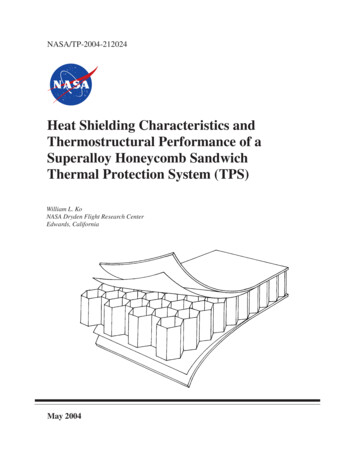
NASA/TP-2004-212024Heat Shielding Characteristics andThermostructural Performance of aSuperalloy Honeycomb SandwichThermal Protection System (TPS)William L. KoNASA Dryden Flight Research CenterEdwards, CaliforniaMay 2004
The NASA STI Program Office in ProfileSince its founding, NASA has been dedicatedto the advancement of aeronautics and spacescience. The NASA Scientific and TechnicalInformation (STI) Program Office plays a keypart in helping NASA maintain thisimportant role.The NASA STI Program Office is operated byLangley Research Center, the lead center forNASA’s scientific and technical information.The NASA STI Program Office provides accessto the NASA STI Database, the largest collectionof aeronautical and space science STI in theworld. The Program Office is also NASA’sinstitutional mechanism for disseminating theresults of its research and development activities.These results are published by NASA in theNASA STI Report Series, which includes thefollowing report types: TECHNICAL PUBLICATION. Reports ofcompleted research or a major significantphase of research that present the results ofNASA programs and include extensive dataor theoretical analysis. Includes compilationsof significant scientific and technical dataand information deemed to be of continuingreference value. NASA’s counterpart ofpeer-reviewed formal professional papers buthas less stringent limitations on manuscriptlength and extent of graphic presentations.TECHNICAL MEMORANDUM. Scientificand technical findings that are preliminary orof specialized interest, e.g., quick releasereports, working papers, and bibliographiesthat contain minimal annotation. Does notcontain extensive analysis.CONTRACTOR REPORT. Scientific andtechnical findings by NASA-sponsoredcontractors and grantees. CONFERENCE PUBLICATION.Collected papers from scientific andtechnical conferences, symposia, seminars,or other meetings sponsored or cosponsoredby NASA. SPECIAL PUBLICATION. Scientific,technical, or historical information fromNASA programs, projects, and missions,often concerned with subjects havingsubstantial public interest. TECHNICAL TRANSLATION. Englishlanguage translations of foreign scientificand technical material pertinent toNASA’s mission.Specialized services that complement the STIProgram Office’s diverse offerings includecreating custom thesauri, building customizeddatabases, organizing and publishing researchresults even providing videos.For more information about the NASA STIProgram Office, see the following: Access the NASA STI Program Home Pageat http://www.sti.nasa.gov E-mail your question via the Internet tohelp@sti.nasa.gov Fax your question to the NASA Access HelpDesk at (301) 621-0134 Telephone the NASA Access Help Desk at(301) 621-0390 Write to:NASA Access Help DeskNASA Center for AeroSpace Information7121 Standard DriveHanover, MD 21076-1320
NASA/TP-2004-212024Heat Shielding Characteristics andThermostructural Performance of aSuperalloy Honeycomb SandwichThermal Protection System (TPS)William L. KoNASA Dryden Flight Research CenterEdwards, CaliforniaNational Aeronautics andSpace AdministrationDryden Flight Research CenterEdwards, California 93523-0273May 2004
NOTICEUse of trade names or names of manufacturers in this document does not constitute an official endorsementof such products or manufacturers, either expressed or implied, by the National Aeronautics andSpace Administration.Available from the following:NASA Center for AeroSpace Information (CASI)7121 Standard DriveHanover, MD 21076-1320(301) 621-0390National Technical Information Service (NTIS)5285 Port Royal RoadSpringfield, VA 22161-2171(703) 487-4650
CONTENTSPageABSTRACT . . . . . . . . . . . . . . . . . . . . . . . . . . . . . . . . . . . . . . . . . . . . . . . . . . . . . . . . . . . . . . . . . . . . . . . . 1NOMENCLATURE . . . . . . . . . . . . . . . . . . . . . . . . . . . . . . . . . . . . . . . . . . . . . . . . . . . . . . . . . . . . . . . . . . 1INTRODUCTION . . . . . . . . . . . . . . . . . . . . . . . . . . . . . . . . . . . . . . . . . . . . . . . . . . . . . . . . . . . . . . . . . . . . 3DESCRIPTION OF PROBLEM . . . . . . . . . . . . . . . . . . . . . . . . . . . . . . . . . . . . . . . . . . . . . . . . . . . . . . . . . 4HONEYCOMB STRUCTURES . . . . . . . . . . . . . . . . . . . . . . . . . . . . . . . . . . . . . . . . . . . . . . . . . . . . . . . . .Honeycomb Construction . . . . . . . . . . . . . . . . . . . . . . . . . . . . . . . . . . . . . . . . . . . . . . . . . . . . . . . . . . .Honeycomb Cells . . . . . . . . . . . . . . . . . . . . . . . . . . . . . . . . . . . . . . . . . . . . . . . . . . . . . . . . . . . . . . . . .Effective Densities . . . . . . . . . . . . . . . . . . . . . . . . . . . . . . . . . . . . . . . . . . . . . . . . . . . . . . . . . . . . . . . .Cell Sizes . . . . . . . . . . . . . . . . . . . . . . . . . . . . . . . . . . . . . . . . . . . . . . . . . . . . . . . . . . . . . . . . . . . . . . . .Numerical Input Values . . . . . . . . . . . . . . . . . . . . . . . . . . . . . . . . . . . . . . . . . . . . . . . . . . . . . . . . . . . .445567FINITE-ELEMENT ANALYSIS . . . . . . . . . . . . . . . . . . . . . . . . . . . . . . . . . . . . . . . . . . . . . . . . . . . . . . . . 8Heat-Transfer Analysis . . . . . . . . . . . . . . . . . . . . . . . . . . . . . . . . . . . . . . . . . . . . . . . . . . . . . . . . . . . . . 8Thermal Bending Analysis . . . . . . . . . . . . . . . . . . . . . . . . . . . . . . . . . . . . . . . . . . . . . . . . . . . . . . . . . . 9Cell Wall Buckling Analysis . . . . . . . . . . . . . . . . . . . . . . . . . . . . . . . . . . . . . . . . . . . . . . . . . . . . . . . . 11RESULTS . . . . . . . . . . . . . . . . . . . . . . . . . . . . . . . . . . . . . . . . . . . . . . . . . . . . . . . . . . . . . . . . . . . . . . . . .Heat Transfer . . . . . . . . . . . . . . . . . . . . . . . . . . . . . . . . . . . . . . . . . . . . . . . . . . . . . . . . . . . . . . . . . . . .Thermal Bending . . . . . . . . . . . . . . . . . . . . . . . . . . . . . . . . . . . . . . . . . . . . . . . . . . . . . . . . . . . . . . . . .Cell Wall Buckling . . . . . . . . . . . . . . . . . . . . . . . . . . . . . . . . . . . . . . . . . . . . . . . . . . . . . . . . . . . . . . .13131516CONCLUSIONS . . . . . . . . . . . . . . . . . . . . . . . . . . . . . . . . . . . . . . . . . . . . . . . . . . . . . . . . . . . . . . . . . . . . 17FIGURES . . . . . . . . . . . . . . . . . . . . . . . . . . . . . . . . . . . . . . . . . . . . . . . . . . . . . . . . . . . . . . . . . . . . . . . . . . 19APPENDIX . . . . . . . . . . . . . . . . . . . . . . . . . . . . . . . . . . . . . . . . . . . . . . . . . . . . . . . . . . . . . . . . . . . . . . . . 34REFERENCES . . . . . . . . . . . . . . . . . . . . . . . . . . . . . . . . . . . . . . . . . . . . . . . . . . . . . . . . . . . . . . . . . . . . . 39iii
ABSTRACTHeat-transfer, thermal bending, and mechanical buckling analyses have been performed on a superalloy“honeycomb” thermal protection system (TPS) for future hypersonic flight vehicles. The studies focus on theeffect of honeycomb cell geometry on the TPS heat-shielding performance, honeycomb cell wall bucklingcharacteristics, and the effect of boundary conditions on the TPS thermal bending behavior.The results of the study show that the heat-shielding performance of a TPS panel is very sensitive to change inhoneycomb core depth, but insensitive to change in honeycomb cell cross-sectional shape. The thermaldeformations and thermal stresses in the TPS panel are found to be very sensitive to the edge support conditions.Slight corrugation of the honeycomb cell walls can greatly increase their buckling strength.NOMENCLATUREadepth of honeycomb core, or length of a rectangular plate, in.a' 1a, 1.5a, 2a, modified depth of honeycomb core, in.(i)cross-sectional area (perpendicular to the cell axis) of honeycomb cell type i, in2Aw(i)cross-sectional area (perpendicular to the cell axis) of cell walls of honeycomb cell type i, in2bwidth of a rectangular plate, in.bilength of free side of type i honeycomb cell cross section, in.b'length of bonded double side of TPS cell cross section, in.b̃ 5 c, corrugation length of corrugated side of corrugated cell cross section, in.clength of one corrugation leg, in.disize of type i honeycomb cell (maximum diagonal of the cell cross section), in.Dibending stiffness of wall panel of type i honeycomb cell, in-lbEYoung’s modulus, lb/in2Fijradiation view factor, defined as the fraction of radiant heat leaving radiation element i and incident onradiation element jGshear modulus, lb/in2hccorrugation depth (twice the amplitude of corrugation wave), in.iindex (1, 2, 3,.) associated with type i honeycomb cell geometry: i 1 for right hexagonal cell; i 2for square cell; i 3 for TPS flat cell walls; i 4 for TPS corrugated cell wallsAc
iindex (1, 2, 3,.) associated with radiation element ijindex (1, 2, 3,.) associated with radiation element jJLOCjoint locationkbi(i)- ( N z ) , buckling coefficient for a rectangular plate with aspect ratio a b i under uniaxial ----------cr2π Dicompression in a directionlside length of square honeycomb-core sandwich TPS panel, in.mnumber of buckled half-waves in rectangular plate longitudinal directionnnumber of buckled half-waves in rectangular plate lateral direction2(i)( N z ) crclassical compressive buckling load intensity in the z direction of the weakest rectangular wall panel oftype i honeycomb cell, lb/inpone-half of corrugation pitch,qaerodynamic pressure over outer surface of honeycomb-core sandwich TPS panel, lb/in2(i)22c – h c , in.q crcritical value of q at buckling for type i honeycomb cell walls, lb/in2SPARStructural Performance and Resizing (finite-element computer program)STSspace transportation systemttime, sectchoneycomb cell wall thickness, in.t̃ ccorrugated honeycomb cell wall thickness, in.tssandwich face sheet thickness, in.Tlinner face sheet temperature, FTPSthermal protection systemT(t)transient surface temperature over outer surface of honeycomb-core sandwich TPS panel, FTuouter face sheet temperature, FvPoisson’s ratiowedeflection at sandwich panel edge midpoint, in.2
w maxmaximum deflection at sandwich panel center, in.Wweight, lbx, y, zrectangular Cartesian coordinatesαcoefficient of thermal expansion, in/in– F T T u – T l , difference between outer and inner face sheet temperatures, Fθcorrugation angle, degρcdensity of material used for honeycomb core and sandwich face sheets, lb/in3ρieffective density of honeycomb core with type i cell geometry, lb/in3i)ρ (sweffective density of sandwich panel with type i honeycomb cell geometry, lb/in3σxstress in x direction induced in the face sheets, lb/in2σystress in y direction induced in the face sheets, lb/in2σzcompressive stress in z direction in the honeycomb cell walls induced by the surface pressure q(i)( σ z ) crcompressive stress in z direction in the honeycomb cell walls at the buckling of the weakest cell wallSubscripts:( ) crcritical value at buckling( )iassociated with type i honeycomb cell geometrySuperscripts:()(i)associated with type i honeycomb cell geometryINTRODUCTIONHypersonic flight vehicles such as the Space Shuttle orbiter are subjected to severe aerodynamic heatingduring flight missions. A thermal protection system (TPS) made of low–thermal conductivity materials is used toinsulate primary structures from overheating so that the vehicle can operate within the design temperature limit(ref. 1). Typical types of TPS include porous silica rigid “tiles” (ref. 2), flexible felt “blanket” (ref. 3), multiwalledtitanium panels with dimpled cores (refs. 4, 5), and so forth. The main disadvantage of the rigid TPS tiles is thefragility of the materials used. After each mission, numerous tiles must be replaced because of surface damageincurred. To eliminate such repairs, a superalloy “honeycomb” TPS is currently being considered for future spacetransportation systems (STSs) (refs. 6, 7). The honeycomb construction provides low density and low thermalconductivity through the TPS thickness. The superalloy TPS is capable of functioning at high temperatures (ref. 8).3
A TPS is exposed to high temperatures on the outer surface and to relatively lower temperatures on the innersurface facing the cooler substructures. This thermal gradient across the TPS thickness will induce thermal bendingmoment, causing the TPS panel to bulge outwardly. A highly efficient TPS could provide large temperaturegradient across its depth; however, excess temperature gradient across the depth could induce excess thermalbending of the TPS panel, thus disturbing the local air flow. Therefore, proper trade studies must be exercised todesign optimum honeycomb TPS structures. Also, the honeycomb TPS will be subjected to aerodynamic pressureloading, and cell walls must be stiff enough to withstand the air load without buckling.This report presents the results of the heat-shielding and thermostructural analyses of honeycomb “sandwich”TPS panels that have different honeycomb cell geometries.DESCRIPTION OF PROBLEMFigure 1 shows a honeycomb-core sandwich TPS panel subjected to transient surface temperature, T ( t ) , andaerodynamic pressure, q, over its entire outer surface. The TPS panel is square with a side length of l, and isfabricated with two identical face sheets with a thickness of t s and a honeycomb core with a depth of a. For agiven material, the overall heat-shielding and thermostructural performances of the honeycomb TPS panel dependon the thickness of the face sheets, depth of the honeycomb core, thickness of the honeycomb cell walls, and sizeand shape of the honeycomb cells.The first problem is to perform geometrical (shape) analysis of different candidate honeycomb cells that havethe same effective density but different geometrical shapes. The second problem is to perform heat-transferanalysis of TPSs with different honeycomb cell geometry. The third problem is to perform the thermal bendinganalysis of the TPS panels subjected to one-sided heating and under different support conditions. The fourthproblem is to perform comparative buckling analysis of different types of honeycomb cell wall panels undercompressive surface air pressure.HONEYCOMB STRUCTURESThis section presents the geometrical analysis of honeycomb cells with different geometry. The honeycombTPS fabrication process also is described.Honeycomb ConstructionThe honeycomb-core structure is fabricated using multiple layers of thin strips of metallic (or nonmetallic)foils joined together and properly deformed (ref. 9). The thin strips are bonded together first at equally spacedparallel zones (fig. 2). The equally spaced bonding zones on one side of each thin strip are staggered with respect tothose on the opposite side. The bonded multiple sheet assembly then is pulled apart in the thickness directionthrough bending of the bonded and free junctures to form a final honeycomb structure (fig. 2). By modifying thewidth of the interfacial bonding belt zones and their spacing, and by pulling apart the multiple layers throughbending deformations to a desired level, a family of different honeycomb cell geometry could be generated.Figure 3 shows the exploded view of the construction of a sandwich panel with upper and lower face sheets to bebonded to the honeycomb core through the brazing process.4
Honeycomb CellsFigure 4 shows four types of honeycomb cell geometry to be analyzed. The honeycomb cell wall thickness forthe first three types is t c . The first type is a right hexagonal cell (fig. 4(a)) with identical side lengths of b 1 . Thesecond type is a square cell (fig. 4(b)) with side lengths of b 2 , which is modified from the right hexagonal cell byreducing the bonding interface length to a minimum of 2t c . The third type is a distorted honeycomb cell with flatcell walls (fig. 4(c)). In this type of honeycomb cell, the bonded side length b' is slightly less than the free sidelength b 3 , and the angle between the two adjacent free cell walls is adjusted to be 90 degrees.The fourth geometry type is also a distorted honeycomb cell, but the free cell walls are corrugated (fig. 4(d)).Each corrugated wall has five corrugation legs. Cell wall thickness for the fourth type is either t c or t̃ c ( t c ),which decreases with increasing corrugation depth, hc , for maintaining constant core density (fig. 5). The third andfourth types of distorted honeycomb cells have the same linear dimensions (that is, identical b' and b 4 b 3 ), andare the approximate cell geometry of the proposed superalloy TPS for a new STS. The size, d i ( i 1, 2, 3, 4 ) , ofeach type of honeycomb cell is defined as the maximum diagonal of the cell cross section (fig. 4).Effective Densities(i)(i)If A c and A w , respectively, are the cross-sectional areas (perpendicular to the cell axis) of honeycomb celltype i and its cell walls, then the effective density of honeycomb core with type i cell geometry, ρi (face sheetsexcluded), is given by the following:(i)Awρ- ; ( i 1, 2, 3, 4 )-----i -------(i)ρcAc(1)where ρ c is the density of the material used for the honeycomb core and sandwich face sheets.The density of the sandwich panel (including honeycomb core and face sheets) can be written as the following:(i)ρ sw--------- ρc(t)(i)A w a 2t s A c------------------------------------(i)(i)A c a 2t s A cρ2t-----i ------sρca ------------------2ts1 ------a(2)in which equation (1) was used. The weight W of the TPS panel is given byρ (i) 22 W ρ sw l ( a 2t s ) l ρ c 2t s a -----i ρ c (3)5
(i)In the calculations of A w , only one-half thickness of the cell wall was used because each of the cell wallpanels is mutually shared by two adjacent cells. Namely, the unit cell wall thickness is 2t c 2 t c for the bondeddouble walls and t c 2 for the free walls. The effective densities for the four types of honeycomb cores can bewritten as follows (see the appendix for detailed calculations):Right hexagonal cell (i 1):(1)dρ1Aw8 3t16 3t----- --------- --------------c- -----------------c- ; b 1 -----1(1)2ρc9b 19d 1Ac(4)Square cell (i 2):(2)ttcAwρ22- 2 ----c- 2 2 ----; b 2 ------- d 2----- --------(2)2bdρc22Ac(5)TPS cell (flat wall) (i 3):(3)ttcAwρ328 23 2; b 3 ---------- d 3----- --------- --- ( 3 2 ) ----c- ---------- ( 3 2 ) ----(3)5158b3d3ρcAc(6)TPS cell (corrugated wall) (i 4):2 t̃ρ4 t̃ c256 h c2 b̃8 2 ----- --- 3 ----- 2 ----- ---------- 3 1 --------- ----- 2 -----c ; b 4 3---------2- d 4 d3 d25 b415 ρc8 b4 44(7)in which the following expression for corrugation length b̃ was used (fig. 5 and appendix):2b̃----- b4h1 24 ----c- 2b42256 h1 --------- -----c3 d2(8)4Cell SizesTo compare the heat-shielding and buckling performances, the size of honeycomb cells types 1, 2, and 4 areadjusted to have the same effective density as that of honeycomb cell type 3 (that is, ρ 1 ρ 2 ρ 3 ρ 4 ). Byequating equations (4) and (6), and equations (5) and (6), the cell sizes d 1 and d 2 are determined as10 3d 1 -------------------------------- d 33 2( 2 3)6(9)
15d 2 ------------------------d 34( 2 3)(10)Figure 6 shows the plots of d 1 and d 2 as functions of d 3 based on equations (9) and (10). For the corrugatedcell, by definitiond4 d3(11)and to maintain the same effective density (that is, ρ 4 ρ 3 ), the corrugated cell wall thickness t̃ c is reduced asthe corrugation depth h c increases according to the following equation (see appendix).t̃3 23 23 2---c- ------------------------------------------ ---------------------------------------------- ; b 4 ---------- d 48tc22hc256 h c3 1 --------- ----- 23 1 24 ----- 223 d2b44(12)Figure 7 shows the corrugation angle, θ , plotted as a function of corrugation depth h c t c ; figure 8 shows thecorrugated cell wall thickne
help@sti.nasa.gov Fax your question to the NASA Access Help Desk at (301) 621-0134 Telephone the NASA Access Help Desk at (301) 621-0390 Write to: NASA Access Help Desk NASA Center for AeroSpa
