Transcription
U.S. Department of Housing and Urban DevelopmentOffice of Policy Development and ResearchResidential Structural Design Guide:2000 EditionA State-of-the-Art Review and Application ofEngineering Information for Light-Frame Homes,Apartments, and Townhouses
PATH (Partnership for Advanced Technology in Housing) is a new private/public effort to develop, demonstrate,and gain widespread market acceptance for the “Next Generation” of American housing. Through the use of new orinnovative technologies the goal of PATH is to improve the quality, durability, environmental efficiency, andaffordability of tomorrow’s homes.Initiated at the request of the White House, PATH is managed and supported by the Department of Housing andUrban Development (HUD). In addition, all Federal Agencies that engage in housing research and technologydevelopment are PATH Partners, including the Departments of Energy and Commerce, as well as the EnvironmentalProtection Agency (EPA) and the Federal Emergency Management Agency (FEMA). State and local governmentsand other participants from the public sector are also partners in PATH. Product manufacturers, home builders,insurance companies, and lenders represent private industry in the PATH Partnership.To learn more about PATH, please contact:Suite B133451 7th Street, SWWashington, DC 20410202-708-4250 (fax)e-mail: pathnet@pathnet.orgwebsite: www.pathnet.org
Residential Structural Design Guide:2000 EditionA State-of-the-Art Review and Application ofEngineering Information for Light-Frame Homes,Apartments, and TownhousesPrepared forU.S. Department of Housing and Urban DevelopmentOffice of Policy Development and ResearchWashington, DCContract H-21065CAandNational Association of Home BuildersHousing Affordability Through Design Efficiency ProgramWashington, DCbyNAHB Research Center, Inc.Upper Marlboro, MarylandFebruary 2000
AcknowledgmentsThis document was prepared by the NAHB Research Center, Inc. The work wassponsored by the U.S. Department of Housing and Urban Development (HUD) and cofunded bythe National Association of Home Builders (NAHB). The principal authors of the guide are JayCrandell, P.E., and Andrea Vrankar, P.E., R.A., with contributions from Donald F. Luebs.Graphics were produced by Barbara Vrankar Karim, Lisa Zimmerman, and Mary Ellen Howard.Special appreciation is extended to William Freeborne and Riley Chung of HUD for their reviewand guidance throughout the project. Appreciation is also extended to the following individualswhose comments made this work more complete: Patrick Bridges, Bridges and Associates;Dr. Eric F.P. Burnett, Pennsylvania Housing Research Center; Kirk Grundahl, Wood TrussCouncil of America; David Mason, Southern Forest Products Association; and Mark Nowak,NAHB Research Center, Inc. A special thank you is extended to David Gromala, Brad Douglas,David Rosowsky, Thomas Williamson, and Michael Baker for their instructive criticism andtechnical suggestions that significantly improved the soundness of this work. The significanteditorial contributions of Carol Soble are certainly recognized for the improved quality of thiswriting. Finally, for the hours of hard work and rework in pulling this document together, theauthors extend many thanks to Lynda Marchman.ABOUT THE NAHB RESEARCH CENTER, INC.The NAHB Research Center is a not-for-profit subsidiary of the National Association of Home Builders (NAHB).The NAHB has 190,000 members, including 50,000 builders who build more than 80 percent of new Americanhomes. NAHB Research Center conducts research, analysis, and demonstration programs in all areas relating tohome building and carries out extensive programs of information dissemination and interchange among members ofthe industry and between the industry and the public.NOTICEThe contents of this report are the views of the contractor and do not necessarily reflect the views or policies of theU.S. Department of Housing and Urban Development or the U.S. government.While the information in this document is believed to be accurate, neither the authors, nor reviewers, nor the U.S.Department of Housing and Urban Development, nor the NAHB Research Center, Inc., nor any of their employees orrepresentatives makes any warranty, guarantee, or representation, expressed or implied, with respect to the accuracy,effectiveness, or usefulness of any information, method, or material in this document, nor assumes any liability for theuse of any information, methods, or materials disclosed herein, or for damages arising from such use. This publication isintended for the use of professional personnel who are competent to evaluate the significance and limitations of thereported information and who will accept responsibility for the application of the material it contains. All responsibilityas to the appropriate use of information in this document is the responsibility of the reader or user.The U.S. government does not endorse products or manufacturers. Trade or manufacturer’s names that appear hereinare used solely because they are considered essential to the objective of this report.iiResidential Structural Design Guide
ForewordThe increasing complexity of homes, the use of innovative materials andtechnologies, and the increased population in high-hazard areas of the United States haveintroduced many challenges to the building industry and design profession as a whole.These challenges call for the development and continual improvement of efficientengineering methods for housing applications as well as for the education of designers inthe uniqueness of housing as a structural design problem.This text is an initial effort to document and improve the unique structuralengineering knowledge related to housing design and performance. It complimentscurrent design practices and building code requirements with value-added technicalinformation and guidance. In doing so, it supplements fundamental engineering principleswith various technical resources and insights that focus on improving the understandingof conventional and engineered housing construction. Thus, it attempts to addressdeficiencies and inefficiencies in past housing construction practices and structuralengineering concepts through a comprehensive design approach that draws on existingand innovative engineering technologies in a practical manner. The guide may be viewedas a “living document” subject to further improvement as the art and science of housingdesign evolves.We hope that this guide will facilitate and advance efficient design of futurehousing whether built in conformance with prescriptive (i.e., “conventional”) practices orspecially engineered in part or whole. The desired effect is to continue to improve thevalue of American housing in terms of economy and structural performance.Susan M. WachterAssistant Secretary for PolicyDevelopment and Research
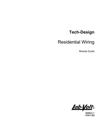
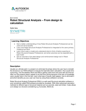
PrefaceThis document is a unique and comprehensive tool for design professionals,particularly structural engineers, seeking to provide value-added services to the producersand consumers of American housing. As such, the guide is organized around thefollowing major objectives: to present a sound perspective on American housing relative to its history,construction characteristics, regulation, and performance experience;to provide the latest technical knowledge and engineering approaches for thedesign of homes to complement current code-prescribed design methods;to assemble relevant design data and methods in a single, comprehensiveformat that is instructional and simple to apply for the complete design of ahome; andto reveal areas where gaps in existing research, design specifications, andanalytic tools necessitate alternative methods of design and sound engineeringjudgment to produce efficient designs.This guide consists of seven chapters. The layout and application of the variouschapters are illustrated in the figure on page vii. Chapter 1 describes the basic substanceof American housing, including conventional construction practices, alternativematerials, building codes and standards, the role of design professionals, and actualexperience with respect to performance problems and successes, particularly as related tonatural hazards such as hurricanes and earthquakes. Chapter 2 introduces basicengineering concepts regarding safety, load path, and the structural system response ofresidential buildings, subassemblies, and components to various types of loads. Chapter 3addresses design loads applicable to residential construction. Chapters 4 and 5 providestep-by-step design procedures for the various components and assemblies comprisingthe structure of a home—from the foundation to the roof. Chapter 6 is devoted to thedesign of light-frame homes to resist lateral loads from wind and earthquakes. Chapter 7addresses the design of various types of connections in a wood-framed home that areimportant to the overall function of the numerous component parts. As appropriate, theguide offers additional resources and references on the topics addressed.Given that most homes in the United States are built with wood structuralmaterials, the guide focuses on appropriate methods of design associated with wood forthe above-grade portion of the structure. Concrete or masonry are generally assumed tobe used for the below-grade portion of the structure, although preservative-treated woodmay also be used. Other materials and systems using various innovative approaches areconsidered in abbreviated form as appropriate. In some cases, innovative materials orsystems can be used to address specific issues in the design and performance of homes.For example, steel framing is popular in Hawaii partly because of wood’s specialResidential Structural Design Guidev
problems with decay and termite damage. Likewise, partially reinforced masonryconstruction is used extensively in Florida because of its demonstrated ability to performin high winds.For typical wood-framed homes, the primary markets for engineering services liein special load conditions, such as girder design for a custom house; corrective measures,such as repair of a damaged roof truss or floor joist; and high-hazard conditions such ason the West Coast (earthquakes) and the Gulf and Atlantic coasts (hurricanes). Thedesign recommendations in the guide are based on the best information available to theauthors for the safe and efficient design of homes. Much of the technical information andguidance is supplemental to building codes, standards, and design specifications thatdefine current engineering practice. In fact, current building codes may not explicitlyrecognize some of the technical information or design methods described orrecommended in the guide. Therefore, a competent professional designer should firstcompare and understand any differences between the content of this guide and localbuilding code requirements. Any actual use of this guide by a competent professionalmay require appropriate substantiation as an "alternative method of analysis." The guideand references provided herein should help furnish the necessary documentation.The use of alternative means and methods of design should not be taken lightly orwithout first carefully considering the wide range of implications related to the applicablebuilding code’s minimum requirements for structural design, the local process ofaccepting alternative designs, the acceptability of the proposed alternative design methodor data, and exposure to liability when attempting something new or innovative, evenwhen carried out correctly. It is not the intent of this guide to steer a designer unwittinglyinto non-compliance with current regulatory requirements for the practice of design asgoverned by local building codes. Instead, the intent is to provide technical insights intoand approaches to home design that have not been compiled elsewhere but deserverecognition and consideration. The guide is also intended to be instructional in a mannerrelevant to the current state of the art of home design.Finally, it is hoped that this guide will foster a better understanding amongengineers, architects, building code officials, and home builders by clarifying theperception of homes as structural systems. As such, the guide should help structuraldesigners perform their services more effectively and assist in integrating their skills withothers who contribute to the production of safe and affordable homes in the UnitedStates.viResidential Structural Design Guide
C H A P T E R 1B A S IC S O F R E S ID E N T IA L C O N S T R U C T IO NyxC H A P T E R 2S T R U C T U R A L D E S IG N C O N C E P T SC H A P T E R 3D E S IG N L O A D S F O RR E S ID E N T IA L B U IL D IN G SC H A P T E R 6L A T E R A L R E S IS T A N C E T OW IN D A N D E A R T H Q U A K E SC H A P T E R 5D E S IG N O F W O O DF R A M IN GC H A P T E R 4D E S IG N O FF O U N D A T IO N SC H A P T E R 7C O N N E C T IO N SC H A P T E R L A Y O U T A N D A P P L IC A T IO N G U ID EResidential Structural Design Guidevii
ContentsPageChapter 1 - Basics of Residential Construction1.11.21.31.41.51.61.71.8Conventional Residential Construction.1-1Industrialized Housing .1-6Alternative Materials and Methods .1-7Building Codes and Standards .1-11Role of the Design Professional .1-14Housing Structural Performance .1-15Summary .1-24References .1-25yChapter 2 - Structural Design Conceptsx2.12.22.32.42.52.6General .2-1What is Structural Design?.2-1Load Conditions and Structural System Response .2-2Load Path.2-6Structural Safety.2-14References .2-23Chapter 3 - Design Loads for Residential l .3-1Load Combinations .3-2Dead Loads.3-4Live Loads.3-6Soil Lateral Loads .3-8Wind Loads .3-11Snow Loads .3-20Earthquake Loads.3-22Other Load Conditions .3-30Design Examples.3-31References .3-38Chapter 4 - Design of Foundations4.1General .4-1Residential Structural Design Guideix
4.24.34.44.54.64.74.84.94.10Material Properties .4-4Soil Bearing Capacity and Footing Size .4-8Footings.4-10Foundation Walls .4-19Slabs on Grade .4-49Pile Foundations.4-50Frost Protection .4-53Design Examples.4-58References .4-88Chapter 5 - Design of Wood Framing5.15.25.35.45.55.65.75.8General .5-1Material Properties .5-3Structural Evaluation.5-15Floor Framing.5-24Wall Framing.5-32Roofs .5-39Design Examples.5-48References .5-81Chapter 6 - Lateral Resistance to Wind and Earthquakes6.16.26.36.46.56.66.7General .6-1Overview of Whole-Building Tests .6-3LFRS Design Steps and Terminology.6-5The Current LFRS Design Practice.6-11Design Guidelines .6-19Design Examples.6-41References .6-74Chapter 7 - Connections7.17.27.37.47.57.6General .7-1Types of Mechanical Fasteners .7-3Wood Connection Design .7-11Design of Concrete and Masonry Connections.7-23Design Examples.7-28References .7-50Appendix A - Shear and Moment Diagrams and Beam EquationsAppendix B - Unit ConversionsxResidential Structural Design Guide
List of FiguresPageChapter 1 - Basics of Residential ConstructionFigure 1.1a:Figure 1.1b:Figure 1.1c:Figure 1.2:Figure 1.3:Figure 1.4:Figure 1.5:Figure 1.6:Figure 1.7:Figure 1.8:yxPost-and-Beam Construction (Historical)Balloon-Frame Construction (Historical)Modern Platform-Frame ConstructionModern Platform-Framed House under ConstructionHouse Construction Using Engineered Wood ComponentsHouse Construction Using Cold-Formed Steel FramingHouse Construction Using Insulating Concrete FormsHouse Construction Using Concrete MasonryUse of Model Building Codes in the United StatesMaximum Gust Wind Speeds Experienced in Hurricane Andrew1-21-31-41-51-81-91-101-111-121-19Chapter 2 - Structural Design ConceptsFigure 2.1:Figure 2.2:Figure 2.3:Figure 2.4:Figure 2.5:Illustration of the Vertical Load Path for Gravity LoadsIllustration of the Vertical Load Path for Wind UpliftIllustration of the Lateral Load PathIllustration of Building Deformation under Lateral LoadBasic Concept of Safety in LRFD and ASD Consideringthe Variability of Loads and Resistance2-72-82-122-132-21Chapter 3 - Design Loads for Residential BuildingsFigure 3.1:Figure 3.2:Figure 3.3:Figure 3.4:Triangular Pressure Distribution on a Basement Foundation WallBasic Design Wind Speed Map from ASCE 7-98Ground Snow Loads (ASCE 7-98)Seismic Map of Design Short-Period Spectral Response Acceleration (g)(2 percent chance of exceedance in 50 years or 2,475-year return period)3-93-133-213-23Chapter 4 - Design of FoundationsFigure 4.1:Figure 4.2:Figure 4.3:Figure 4.4:Figure 4.5:Types of FoundationsCritical Failure Planes in Continuous or Square Concrete Spread FootingsVariables Defined for Shear Calculations in Plain Concrete WallsVariables Defined for Shear Calculations in Reinforced Concrete WallsTypical Interaction Diagrams for Plain and Reinforced Concrete WallsResidential Structural Design Guide4-34-134-224-254-29xi
Figure 4.6: Design Variables Defined for Lintel Bending and ShearFigure 4.7: Variables Defined for Shear Calculations in Reinforced ConcreteMasonry WallsFigure 4.8: Concrete Masonry Wall Lintel TypesFigure 4.9: Preservative-Treated Wood Foundation WallsFigure 4.10: Insulating Concrete Form Foundation WallsFigure 4.11: Basic Coastal Foundation ConstructionFigure 4.12: Air-Freezing Index Map (100-Year Return Period)Figure 4.13: Frost-Protected Shallow Foundation r 5 - Design of Wood FramingFigure 5.1:Figure 5.2:Figure 5.3:Figure 5.4:Figure 5.5:Figure 5.6:Figure 5.7:Figure 5.8:Figure 5.9:Components and Assemblies of a Conventional Wood-Framed HomeStructural Elements of the Floor SystemConventional and Alternative Floor Framing MembersExamples of Beams and GirdersStructural Elements of the Wall SystemWood Column TypesStructural Elements of a Conventional Roof SystemDesign Methods and Assumptions for a Sloped Roof RafterTypical Roof Overhang pter 6 - Lateral Resistance to Wind and EarthquakesFigure 6.1: Chords in Shear Walls and Horizontal Diaphragms Using the“Deep Beam” AnalogyFigure 6.2: Shear Wall Collector and the Composite Failure Plane (Failure planealso applies to diaphragm chords)Figure 6.3: Two Types of Hold-Down Restraint and Basic Analytic ConceptsFigure 6.4: Lateral Force Distribution by a “Flexible” Diaphragm(tributary area approach)Figure 6.5: Illustration of a Basic Perforated Shear WallFigure 6.6: Evaluation of Overturning Forces on a Restrained Shear Wall Segment6-76-86-106-126-176-33Chapter 7 - ConnectionsFigure 7.1:Figure 7.2:Figure 7.3:Figure 7.4:Figure 7.5:Figure 7.6:Figure 7.7:xiiElements of a Nail and Nail TypesBolt and Connection TypesSpecialty Connector HardwareTypes of Connections and Loading ConditionsConcrete or Masonry Wall-to-Footing ConnectionsKey in Concrete FootingsDowel Placement in Concrete Footings7-47-87-107-137-247-257-26Residential Structural Design Guide
Appendix A: Shear and Moment Diagrams and Beam EquationsFigure A.1:Figure A.2:Figure A.3:Figure A.4:Figure A.5:Figure A.6:Simple Beam (Foundation Wall) - Partial Triangular LoadSimple Beam (Wall or Column) – Eccentric Point LoadSimple Beam – Uniformly Distributed LoadSimple Beam – Load Increasing Uniformly to One EndSimple Beam – Concentrated Load at Any PointSimple Beam – Two Unequal Concentrated LoadsUnsymmetrically PlacedFigure A.7: Cantilever Beam – Uniformly Distributed LoadFigure A.8: Cantilever Beam – Concentrated Load at Any PointFigure A.9: Beam Fixed at One End, Supported at Other –Uniformly Distributed LoadFigure A.10: Beam Fixed at One End, Supported at Other –Concentrated Load at Any PointFigure A.11: Beam Fixed at Both Ends – Uniformly Distributed LoadsFigure A.12: Beam Fixed at Both Ends – Concentrated Load at Any PointFigure A.13: Beam Overhanging One Support – Uniformly Distributed LoadFigure A.14: Beam Overhanging One Support – Concentrated Load atEnd of OverhangFigure A.15: Continuous Beam – Two Equal Spans and Uniformly Distributed LoadFigure A.16: Continuous Beam – Two Equal Spans with Uniform Load on One SpanFigure A.17: Continuous Beam – Two Unequal Spans and Uniformly Distributed LoadResidential Structural Design A-9A-9xiii
xivResidential Structural Design Guide
List of TablesPageChapter 1 - Basics of Residential ConstructionTable 1.1:Table 1.2:Table 1.3:Table 1.4:Table 1.5:yxTop Five House Defects Based on Homeowner Warranty ClaimsConstruction Characteristics of Sampled Single-Family DetachedHomes in Hurricane AndrewComponents of Sampled Single-Family Detached Homes with“Moderate” or “High” Damage Ratings in Hurricane AndrewConstruction Characteristics of Sampled Single-FamilyDetached DwellingsDamage to Sampled Single-Family Detached Homes in the NorthridgeEarthquake (percent of sampled homes)1-171-181-191-221-22Chapter 2 - Structural Design ConceptsTable 2.1:Table 2.2:Table 2.3:Table 2.4:Building Loads Categorized by OrientationEffect of Safety Factor on Level of Safety in ASD for a TypicalHurricane-Prone Wind ClimateCommonplace Risks and Mortality RatesAnnual Economic Losses of Insured Buildings Associatedwith Wind Damage2-22-192-222-23Chapter 3 - Design Loads for Residential BuildingsTable 3.1:Typical Load Combinations Used for the Design of Componentsand SystemsTable 3.2: Dead Loads for Common Residential ConstructionTable 3.3: Densities for Common Residential Construction MaterialsTable 3.4: Live Loads for Residential ConstructionTable 3.5: Values of Ka, Soil Unit Weight, and Equivalent Fluid Densityby Soil TypeTable 3.6: Wind Speed ConversionsTable 3.7: Basic Wind Velocity Pressures (psf) for Suburban TerrainTable 3.8: Lateral Pressure Coefficients for Application to Vertical Projected AreasTable 3.9: Wind Pressure Coefficients for Systems and Components(enclosed building)Table 3.10: Missile Types for Wind-Borne Debris Impact TestsTable 3.11: Site Soil Amplification Factor Relative to Acceleration(short period, firm soil)Table 3.12: Seismic Response Modifiers for Residential ConstructionResidential Structural Design v
Chapter 4 - Design of FoundationsTable 4.1:Table 4.2:Table 4.3:Table 4.4:Table 4.5:Table 4.6:Table 4.7:Table 4.8:Rebar Size, Diameter, and Cross-Sectional AreasPresumptive Soil Bearing Values by Soil DescriptionPresumptive Soil Bearing Values (psf) Based on StandardPenetrometer Blow CountSimplified Moment Magnification Factors, δnsNominal Wall Thickness for 8-Foot-High Masonry Foundation WallsAllowable Flexural Tension Stresses Fa for Allowable Stress Designof Unreinforced MasonryPreservative-Treated Wood Foundation FramingMinimum Frost Depths for Residential Footings4-64-84-94-274-354-364-474-54Chapter 5 - Design of Wood FramingTable 5.1:Table 5.2:Table 5.3:Table 5.4:Table 5.5:Table 5.6:Table 5.7:Table 5.8:Design Properties and Associated Reduction Factors for ASDAdjustment Factor Applicability to Design Values for WoodRecommended Load Duration Factors for ASDRecommended Repetitive Member Factors for DimensionLumber Used in Framing SystemsRecommended Allowable Deflection LimitsSystem Deflection Adjustment FactorsFastening Floor Sheathing to Structural MembersRecommended System Adjustment Factors for Header Design5-105-105-125-135-215-225-315-37Chapter 6 - Lateral Resistance to Wind and EarthquakesTable 6.1:Table 6.2:Table 6.3:Table 6.4:Table 6.5:Table 6.6:Table 6.7:Table 6.8:xviUnfactored (Ultimate) Shear Resistance (plf) for Wood StructuralPanel Shear Walls with Framing of Douglas-Fir, Larch, or Southern PineUnfactored (Ultimate) Unit Shear Resistance (plf) for Walls withCold-Formed Steel Framing and Wood Structural PanelsUnfactored (Ultimate) Unit Shear Values (plf) for 1/2-Inch-ThickGypsum Wall Board SheathingUnfactored (Ultimate) Shear Resistance (lbs) for 1x4 Wood Let-insand Metal T-BracesMinimum Recommended Safety and Resistance Factors forResidential Shear Wall DesignSpecific Gravity Values (Average) for Common Speciesof Framing LumberValues of Cns for Various Nail Sizes and TypesHorizontal Diaphragm ASD Shear Values (plf) for unblocked Roofand Floor Construction Using Douglas Fir or Southern Pine Framing6-226-236-246-256-296-296-306-38Residential Structural Design Guide
Chapter 7 - ConnectionsTable 7.1:Table 7.2:Table 7.3:Recommended Nailing Schedule for a Wood-Framed HomeNail Types, Sizes, and DimensionsCommon Framing Lumber Species and Specific Gravity ValuesResidential Structural Design Guide7-27-6
Residential Structural Design Guide v Preface This document is a unique and comprehensive tool for design professionals, particularly structural engineers, seeking to provide value-added services to the producers and consumers of American housing. As such, the guide is organized around the following major objectives: