Transcription
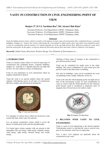
IJRET: International Journal of Research in Engineering and 027eISSN: 2319-1163 pISSN: 2321-7308Received: 16-05-2018, Accepted: 27-06-2018, Published: 18-07-2018TELECOM COMMUNICATION STRUCTURESSankara Ganesh DhoopamGeneral Manager (Head)-Engineering, Ramboll India PVT Ltd, Hyderabad, Telangana, India, ganeshd@ramboll.inAbstractThe Indian tower industry has witnessed many key changes in the past few years from basic calling services to data drivenservices. Ongoing digital revolution, Indian government thrust on digital India and smart cities mission becomes essential tosetup a robust telecom infrastructure capable of handling the surging amount of data traffic. As per government report, themobile sector’s contribution to GDP will increase to 8.2 percent by 2020 from 6.5 percent at present. Given the hypercompetitivemarket situation and the explosive data demand, the relevance of network infrastructure is only going to increase despite thechallenges. Telecom companies current focus associated to tower infrastructure is mainly on optimization by keeping low costtower structure, compact sites, energy savings and utilization of existing towers to the peak capacity by with or withoutstrengthening. Also equal focus on building innovative aesthetic structures and street smart infrastructures like street light poles,smart cells for speeding up the network capabilities suitable to 4G/5G networks and combined with other society needs like videosurveillance, weather monitoring sensors, advertisement hoardings and other local traffic signal requirements.Keywords: - Telecom tower, Tubular tower, Tower sharing, Tower strengthening, Renewable energy, Full scale towertesting, Wind loads, Colocation, Appurtenances, GSM antenna, Microwave antenna, Angular tower, optimisation ---------------------------------------------1. INTRODUCTIONIn the past one decade, India telecom sector has registeredstrong growth to reach as subscriber base of 1,201.72Million as on October 2017, accounted for the 2 nd largesttelecom network in the world with a 4,60,000 Telecomsites and second highest number of internet users429.23Million. This rapid growth in telecom network in theuse of cellular phones for voice and data has created manytelecom towers on ground and buildings having heightranges of 3m to 90m. With the exponential data growth andgrowing subscriber base additional sites needed forincreased capacity across technologies with 3% year averagegrowth from now.In a competitive market with low data tariffs and low profitlevels to telecom companies, there is a strong need inexploring cost effective ways in optimizing infrastructurelike mobilising optimized new telecom towers, utilizing ofexisting towers to the peak capacity with or withoutstrengthening and alternative power saving solutions.About 40% total telecom towers faces interrupted powersupply say about 12hours per day, resulting relaying ondiesel generators (D.G), batteries and number of otherpowermanagement equipment to ensure grid backup and networkavailability. Excessive dependence on DGs resultingenvironmental issue of carbon emissions. Sustainabletelecommunications emphasize energy efficiency byadopting renewable energy solutions like solar and windsources in modern telecom networks.The Indian government is planning to develop 100 smartcity projects, where IoT (Internet of things) would play avital role in development of these cities. IoT conceptprimarily collect and monitor the real-time data and providewide controlled analytics for better safety of citizens in thecities. Success of IoT depends on the speed and precisetransfer of real time data, so its important to integrate mobilenetwork associated with city monitoring equipment. Fromthe requirement, the development of “Aesthetic smart citystructures” creates huge demand in future blending into thecity heritage.Mentioning above introduction, it is important that Telecomdesign engineers should be aware on the cost optimizationsand significance of keeping network up all the time bycreating safe and sound healthy structures asmostly thesestructures located in public areas. There were no directrecognized India codes available for design of lattice towers& masts and current references did not cover the modernanalysis and design in a sufficient manner compared to otherinternational standards. Therefore, it is very importantTelecom structural engineers should discuss on new designs,technical papers and exchanging experiences to accumulatethe knowledge in one place. It is highly recommendable toinclude the analysis and design of communication structuresVolume: 07 Issue: 07 Jul-2018, Available @ www.ijret.org201
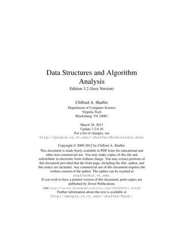
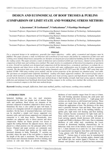
IJRET: International Journal of Research in Engineering and 027Received: 16-05-2018, Accepted: 27-06-2018, Published: 18-07-2018in the education of structural engineering at the engineeringuniversities, and young engineers starting their professionalcareers with introduction to this field in collegeother thanalready from experienced persons from the industry.This paper highlights some of the Ramboll engineeringexperiences and developments in the telecom designengineering domain.2.TUBULARTOWER–ANeISSN: 2319-1163 pISSN: 2321-7308OPTIMIZEDangles or tubes are the key factorsdeciding the optimisationof tower and foundations.Refer to the wind load code (IS 875 (Part 3) – 2015) for dragcoefficients based on tower cross sections and profiles used,three legged tubular towers having less drag coefficientscompared to three legged angular or 4-legged angular tower.So, selection of three-legged tubular has less wind load dueto tower body helps in optimised tower weights and lesstower reactions on foundations.STRUCTURAL SOLUTIONThe First step in proposing an optimised structural solutionis collecting the specifications from the customer comprisesof Location & height of tower Antenna & cables data Accessories requirement (Access & cable ladder,platforms, antenna mounts, Lighting rod, aviation lamp)Based on the specifications, designers will work onpreliminary design by carrying out analysis and design byusing sophisticated 3D FEM programs like iTower,RAMTower, STAAD, PLS Tower and RISA TNXprograms. Preliminary design iterations done by choosingdifferent tower geometry of varying cross sections (4legged/3legged/6 legged/monopole), base widths, bracingpattern combinations based on the force flow, selection ofprofiles (Tubes/angles) for structural members etc., to workout most optimised tower design for the set of givenspecifications.Optimised tower design shall not only comprises of lesstower weight,less number of tower members for fabricationand installation, but it shall also require accounting for theforces coming on to the ground which decides thefoundation cost and footprint for land acquisition.As lattice towers are comparatively light structures andmaximum wind pressure is chief criterion for design.Concurrence of earthquake and maximum wind pressure isunlikely to take place, in earthquake prone area the design oftower and foundations shall be checked for earthquakeforces.As the wind load is most governing for the design, it isimportant to calculate wind load on tower body, antennas,ladder, cables, platforms and other accessories exposed towind facing as accurately as possible inline with stipulationsprovided in the loading &design codes. While calculation oftower body wind, choosing of tower cross section eitherthree legged or four legged and selection of profiles eitherDrag coefficients for tower structures (IS 875 (Part 3))Within the given cross-sectional area and weightscomparingtubes to angles, tubes have high radius of gyrationresulting lower slenderness ratio to achieve higher capacityin compressionfor the same cross sectional area profile.Selecting of angular towers needed more redundantmembers to economize the tower there by increasing thenumber of different elements for production and installationtime. Still the overall weight of angular tower andfoundation are higher than the tubular tower. However,tubes required special attention of welding for joints andgussets.L150x150x12T219.1x4.8Example comparison(Yieldstress 350MPa)Cross sectional area, ARadius of gyration,rxx ryy34.8cm232.32cm24.63cm7.58cmRadius of gyration, rvv2.97cm7.58cm3Section modulus, Z68.8cm169.4cm3WeightSlenderness ratio @2500mm length on rvvCapacity asper IS 8002007( m0 1.0)27.3kg/m25.37kg/m84.232.30636kN996kNVolume: 07 Issue: 07 Jul-2018, Available @ www.ijret.org202
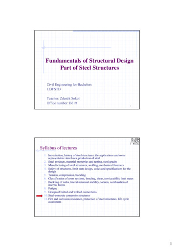
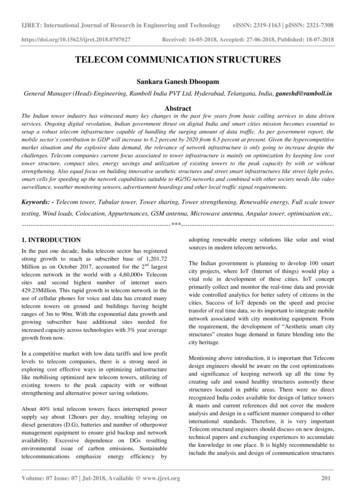
IJRET: International Journal of Research in Engineering and 027eISSN: 2319-1163 pISSN: 2321-7308Received: 16-05-2018, Accepted: 27-06-2018, Published: 18-07-2018Ramboll3 Legged Tubular towerFoundation construction – Isolated/Single pads3.UNIQUEFEATUREWITHTUBULARTOWERSTubular towers has unique advantages compared to otherconfigurations like low weight, simplicity, easy transport,fast assembly, low maintenance costs and less foundationcosts.Connection details of bracing membersApart from tower being cost efficient and superior quality,the additional features can be integrated to the towersolution like quick build foundation, integrated equipmentplatform & fence and renewable energy solutions like solar& wind.3.1 Quick Build FoundationCast in part detailsVolume: 07 Issue: 07 Jul-2018, Available @ www.ijret.org203
IJRET: International Journal of Research in Engineering and 027eISSN: 2319-1163 pISSN: 2321-7308Received: 16-05-2018, Accepted: 27-06-2018, Published: 18-07-20183.2 Renewable Energy (Solar Structure on Tower)4.STRUCTURALASSESSMENT&STRENGTHENING OF EXISTING TELECOMSITESTelecom operators across the world have been witnessing adecline in their profit margins and ARPUs (Average revenueper user) due to growing level of competition, not just frompeers but also from content providers. There byoperators/infrastructure companies are trying to reduce theiroperating costs utilising the existing infrastructureeffectively to the optimum usage by sharing. By sharing thetower, there will be savings on renting of sites, sitemaintenance, manpower, electricity, air-conditioning andfuel expenses etc.3.3 Renewable Energy (Wind Turbine on Tower)3.4 Compact Site (Integrated Equipment Platform& Fence)Therefore, engineering emphasis required on structuralassessment of existing structures and retrofitting ofstructures to take additional loads of multiple operators (or)change in loading and design standards (o)r degradation ofmaterial like corrosion or operational requirements e.g.,twist & sway.Before an existing structure is modified or additional loadsare added to it, following shall be considered,(a) The physical condition and loading of the structure shallbe verified by inspection.Tower configuration and thesize of structural members must be collected to mapwith the known tower design type from available towerdesign database.If there are no existing tower designdocuments available,complete tower structural data hasto be collected to perform the structural analysis.(b) Reporting of observations on tower structural conditionlike damage of members, loose members, missingmembers, cracks, foundation bolt & nut locking devicesmissing and painting conditions etc. Similarobservations required on foundation concrete and soilsettlement and back fill conditions.(c) The structural adequacy of the structure shall beevaluated in accordance with applicable loading &design requirements.Customer tower sharing requirements from differentoperators required to carryout a site specific tower analysisfor the existing antenna loading and proposed new antennaloading. If analysis results found tower members areoverutilized on account of fully capacity or overloading oftowers, the options available to make use of tower are,1)decrease the load on tower either by removing of antennasor 2) truncating tower at top or 3) strengthen the towermembers by the methodology as provide earlier. Removingof antenna or truncating of tower is not a solution fromVolume: 07 Issue: 07 Jul-2018, Available @ www.ijret.org204
IJRET: International Journal of Research in Engineering and 027eISSN: 2319-1163 pISSN: 2321-7308Received: 16-05-2018, Accepted: 27-06-2018, Published: 18-07-2018customer business case. Inorder to allow for further loadingon tower, only option available is to strengthen the towermembers and foundations.4.2 Laboratory Experiments4.2.1 Pipe Samples with & without StrengtheningCommon structural shortfalls can be observed during theanalysis for over loading of towers.#12345FailureconditionsCompression &Tension failureof membersFailure of s1. Replacement of members2. Reinforcing of existingmembers by- Adding of members(Built -up)- Star angle using clamps forangular towers- Adding flats using clamps fortubular towers3.Converting of single lacing toX-Bracings(vis-versa)1. Replacement of Memberwith higher thickness2. Replacing of bolts withhigher Adding secondary MembersGuyed solutions1. Soil stabilization2. Local strengthening of pad &Chimney4.2.3 Test Setup4.1 Analytical &Experimental Studies Carried OutRecently, few researchers have studied the strengthening ofsteel angle members through adding of same size of built ofmembers in star and back to back formation. While formingbuilt up members, there is a need of drilling holes orwelding to existing members. This may require temporaryoutage of existing services and approvals from differentoperators impacting revenue and customer serviceinterruption. Hence, alternate connection arrangements areinvestigated to fix strengthening members. The motive ofstudy is to fix new members by dry clamping connections.New angles or flats will be added to existing members andfixed by clamps (bolted) without any holes drilling toexisting members. Experimental studies have been carriedout to check the results in line with the theoretical calculatedresults as per codal formulas. For this study angle and pipeshave been tested in compression capacity with and withoutstrengthening.4.3 Theoretical vs Lab Experimental Test ResultsHot rolled and built up steel members used for carryingaxial compression, usually fail by flexural buckling. Thebuckling strength of these members is affected by residualstresses, initial bow and accidental eccentricities of load. Toaccount for all these factors, the strength of memberssubjected to compression is to be calculated by bucklingclass based on shape and rolling, with consideringimperfection factors.Volume: 07 Issue: 07 Jul-2018, Available @ www.ijret.org205
IJRET: International Journal of Research in Engineering and 027eISSN: 2319-1163 pISSN: 2321-7308Received: 16-05-2018, Accepted: 27-06-2018, Published: 18-07-2018Compressioncapacityof all these testing samples have beencalculated using IS 800:2007 (Indian Code of Practice –General construction in steel)and ANSI/TIA-222-G(American Code – Structural standard for antennasupporting structures and antennas)standards. Standardformulae are based on limit state design. Experimentalresults and theoretical results are compared in below tablesand found that the capacity calculated using codes to thebuckling load at failure are nearly shown the same results.4.3.1 Pipe Test ResultsPipe Results -Str15P-WS-Str36P-WS-Str2DescriptionNo hening(5Clamps)No hening(5Clamps)Avg. Yieldstress forCalculationN/mm 2Experimentalresults, kgAs per standards,theoreticalAvg.IS:800-2007failur( m0 1.0)e loadPipe without stiffeners17670382 &403(Flat)32291382(Pipe)&403 (Flat)382 (Pipe)382(Pipe)&403 (Flat)382(Pipe)&403(Flat)TIA-222-G( 79Pipe with 39500Relative strength(Increase) in%,Experiment &theoreticalVolume: 07 Issue: 07 Jul-2018, Available @ www.ijret.org206
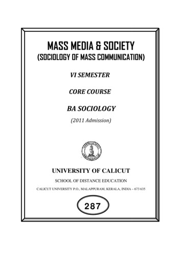
IJRET: International Journal of Research in Engineering and 027eISSN: 2319-1163 pISSN: 2321-7308Received: 16-05-2018, Accepted: 27-06-2018, Published: 18-07-20184.3.2 Angle Test ResultsAngle Results Comparison#Sample1234Sample 1Sample 2Sample 3Sample 4DescriptionAvg. YieldstressforCalculationN/mm 2Plain anglesClampedstarred angles336.7Experimental resultsAvg.Failurefailureload (kg)load (kg)92511043511619126711255712444As per standards, theoreticalIS:800-2007( m0 1.0)TIA-222-G( eAt EndAt EndFurther work on full scale tower testing of 42m telecomtower performed asper the customer requirement.5. FULL SCALE TOWER TESTING OF 42MFOUR-LEGGED ANGULAR TOWERIn four legged angular 42m tower configuration (wind speed180kmph) with all mild steel members (Yield stress 250MPa) has been observed that the main leg members andbracings are over utilised for the new loadings. Therefore, astrengthening scheme have been proposed for the main legsstrengthened by star angles and bracings are strengthened byadding new members to reduce the slenderness ratio, thereby increasing the member capacity. In the scheme, the newmembers are added by dry clamps to the existing towerusing high strength bolts.42m tower was tested for full existing new loadings andwithstood successfully. There was no failure observed inany part of the tower for full design loads (existing newloadings). Tower was further tested for destructive loads(beyond design loads), where the tower bracing member wasbuckled at upper part of tower at other than strengthenedportion.Volume: 07 Issue: 07 Jul-2018, Available @ www.ijret.org207
IJRET: International Journal of Research in Engineering and 027eISSN: 2319-1163 pISSN: 2321-7308Received: 16-05-2018, Accepted: 27-06-2018, Published: 18-07-20187. CONCLUSIONThis paper discusses the telecom tower optimisation,methods of strengthening of angle and pipe profiles. Eventhough today, we have a much better understanding of thebehavior of towers, there are issues like more precisedetermination of the wind resistance of various towers withlinear ancillaries (Antennas, ladders & cables) by provenfull scale wind tunnel tests require further investigations.REFERENCES[1](i) Fixing of new main leg with dry clamping – highstrength bolts (torque tightening)(ii) Fixing of new member for diagonal strengthening(iii) Full scale model testing of towerwith strengthening[2]By individual pipe/angle testing at laboratory and full scaletower model testing on tower test bedhas provided a goodcorrelations with theoretical NG[4]Based on the detailed structural analysis results, designersshall conclude existing tower adequacy for additional loads.In cases where, towers are not having spare capacity to takeadditional loads or cases of under designed towers requiredspecial review and recommendations for strengthening.[5]Below is an example of angular tower strengthened usingstart angle and pipe tower by added vertical flats using dryclamping methodology.[6]Støttrup-Andersen, U, “Analysis and Design of isco, 1998.Francisco, 1998.Nielsen M.G., “Advantages of usingTubular profiles in Telecommunication structures”,11th International symposium on tubular structures,August 2006, Quebec, Canada."Tower sharing & Reinforcement of towers andfoundations" by Sankara Ganesh Dhoopam in 25thIASS WG4 Colloquium, Copenhagen, Denmark,September 2011IS 875 (Part 3) – 2015 - Design Loads (other thanearthquake) for buildings and structures- Code ofPractice part3 Wind LoadsIS 800 :2007 General construction in steel – Code ofpractice.ANSI/TIA-222-G – 2005 Structural Standard forAntenna Supporting Structures and AntennasACKNOWLEDGMENTSThe author gratefully acknowledged and thank themanagement of Ramboll India Private Limited, Hyderabadfor giving the opportunity for conducting the experimentalwork. Any opinions, findings and conclusions orrecommendations expressed in this paper are those of theAuthor. The author also acknowledged the thanks to thesupporters, researchers and writers whose literatures wasused here for supporting this research paper.BIOGRAPHIESSankara Ganesh Dhoopam workingas General manager (Head) –Engineering in Ramboll India,Hyderabad. He is specialised structuralengineer, having 16 years ofexperience in design of steel latticetowers & masts and foundations fortelecom and power transmission linestructures.Volume: 07 Issue: 07 Jul-2018, Available @ www.ijret.org208
size of structural members must be collected to map with the known tower design type from available tower design database.If there are no existing tower design documents available,complete tower structural data has to be collected to perform the structural analysis. (b) Reporting of observations on tower structural condition