Transcription
SE‐007 Design Loads for Residential BuildingsInstructor: Ivan Jelic, Ph.D., P.E., LEED AP, MIStructE, CEngCourse ID: SE‐007PDH Hours: 4 PDHPDH Star T / F: (833) PDH‐STAR (734‐7827) E: info@pdhstar.com
CHAPTER 3Design Loads forResidential Buildings3.1 GeneralLoads are a primary consideration in any building design because they define the nature andmagnitude of hazards or external forces that a building must resist to provide reasonableperformance (that is, safety and serviceability) throughout the structure’s useful life. Theanticipated loads are influenced by a building’s intended use (occupancy and function),configuration (size and shape), and location (climate and site conditions). Ultimately, the typeand magnitude of design loads affect critical decisions such as material selection, constructiondetails, and architectural configuration. To optimize the value (that is, performance versuseconomy) of the finished product, therefore, design loads must be applied realistically.Although the buildings considered in this guide are primarily single-family detached andattached dwellings, the principles and concepts related to building loads also apply to othersimilar types of construction, such as low-rise apartment buildings. In general, the design loadsrecommended in this guide are based on applicable provisions of the ASCE 7 standard–Minimum Design Loads for Buildings and Other Structures (ASCE, 2010). The ASCE 7standard represents an acceptable practice for building loads in the United States and isrecognized in U.S. building codes. For this reason, the reader is encouraged to become familiarwith the provisions, commentary, and technical references contained in the ASCE 7 standard.In general, the structural design of housing has not been treated as a unique engineeringdiscipline or subjected to a special effort to develop better, more efficient design practices. Forthat reason, this part of the guide focuses on those aspects of ASCE 7 and other technicalresources that are particularly relevant to the determination of design loads for residentialstructures. The guide provides supplemental design assistance to address aspects of residentialconstruction for which current practice is either silent or in need of improvement. The guide’sResidential Structural Design Guide3-1
methods for determining design loads are complete yet tailored to typical residential conditions.As with any design function, the designer must ultimately understand and approve the loads fora given project as well as the overall design methodology, including all its inherent strengthsand weaknesses. Because building codes from different jurisdictions can vary in their treatmentof design loads, the designer should, as a matter of due diligence, identify variances from bothlocal accepted practice and the applicable building code relative to design loads as presented inthis guide, even though the variances may be considered technically sound.Complete design of a home typically requires the evaluation of several different types ofmaterials, as discussed in chapters 4 through 7. Some material specifications use the allowablestress design (ASD) approach while others use load and resistance factor design (LRFD).Chapter 4 uses the LRFD method for concrete design and the ASD method for masonrydesign. For wood design, chapters 5, 6, and 7 use ASD. For a single project, therefore, thedesigner may have to determine loads in accordance with both design formats. This chapterprovides load combinations intended for each method. The determination of individualnominal loads is essentially unaffected. Special loads, such as ice loads and rain loads, are notaddressed herein. The reader is referred to the ASCE 7 standard and applicable building codeprovisions regarding special loads.3.2 Load CombinationsThe load combinations in table 3.1 are recommended for use with designspecifications based on ASD and LRFD. Load combinations provide the basic set ofbuilding load conditions that should be considered by the designer. They establish theproportioning of multiple transient loads that may assume point-in-time values whenthe load of interest attains its extreme design value. Load combinations are intendedas a guide to the designer, who should exercise judgment in any particularapplication. The load combinations in table 3.1 are appropriate for use with the designloads determined in accordance with this chapter.The principle used to proportion loads is a recognition that when one loadattains its maximum lifetime value, the other loads assume arbitrary point-in-timevalues associated with the structure’s normal or sustained loading conditions. Theadvent of LRFD has drawn greater attention to this principle (Ellingwood et al., 1982;Galambos et al., 1982). The proportioning of loads in this chapter for ASD isconsistent with design load specifications such as ASCE 7. ASD load combinationsfound in building codes typically have included some degree of proportioning (that is,D W 1/2S) and usually have made allowance for a special reduction for multipletransient loads. Some earlier codes also have permitted allowable material stressincreases for load combinations involving wind and earthquake loads. None of theseadjustments for ASD load combinations are recommended for use with table 3.1because the load proportioning is considered sufficient. However, allowable materialstress increases that are based upon the duration of the load (that is, wood membersunder wind loading) may be combined with load proportioning.Note also that the wind load factor of 1.0 in table 3.1 used for LRFD isconsistent with current wind design practice and now recognizes ultimate wind loadswhen the speeds illustrated in the ASCE 7-10 maps are used. The return period of thedesign wind speeds for residential buildings along the hurricane-prone coast is nowResidential Structural Design Guide3-2
700 years, and this long return period provides a consistent risk basis for wind designacross the country. Many elements of residential design continue to use ASD designlevel wind speeds, however, primarily because of how products have been tested,rated, and marketed to the industry. Some prescriptive design documents such as theWood Frame Construction Manual (WFCM) continue to use ASD load combinationsin the development of loads provided in the design tables of that document (AWC,2012). The conversion of LRFD speeds to ASD speeds is ASD speed LRFDspeedx 0.6. The conversion of LRFD pressures to ASD pressures is ASD windpressure LRFD pressure x 0.6 (the ASD wind load factor). The load factor changesused in ASCE 7-10 are referenced in the 2012 editions of the building codes whereASCE 7-10 is referenced.The load combinations in table 3.1 are simplified and tailored to specificapplication in residential construction and the design of typical components andsystems in a home. These or similar load combinations often are used in practice asshortcuts to those load combinations that govern the design result. This guide makeseffective use of the shortcuts and demonstrates them in the examples provided later inthe chapter. The shortcuts are intended only for the design of residential light-frameconstruction.Residential Structural Design Guide3-3
TABLE 3.1Typical Load Combinations Used for the Design ofComponents and Systems1Component or SystemFoundation wall(gravity and soil lateral loads)Headers, girders, joists, interior loadbearing walls and columns, footings(gravity loads)Exterior load-bearing walls andcolumns (gravity and transverselateral load) 3Roof rafters, trusses, and beams; roofand wall sheathing (gravity and windloads)Floor diaphragms and shear walls(in-plane lateral and overturningloads) 6ASD Load CombinationsLRFD Load CombinationsD HD H 0.75 (Lr or S) 0.75L21.2D 1.6H1.2D 1.6H 1.6L2 0.5(Lr S)1.2D 1.6H 1.6(Lr or S) L2D 0.75 L2 0.75 (Lr or S)D 0.75 (Lr or S) 0.75 L21.2D 1.6L2 0.5 (Lr or S)1.2D 1.6(Lr or S) L2Same as immediately above,plus 0.6D 0.6WD 0.7E 0.75L2 0.75S4D (Lr or S)0.6D 0.6Wu50.6D 0.6WSame as immediately above, plus1.2D 1.0W1.2D 1.0E L2 0.2S41.2D 1.6(Lr or S)0.9D 1.0Wu51.2D 1.0W0.6D (0.6W or 0.7E)0.9D (1.0W or 1.0E)Notes:1The load combinations and factors are intended to apply to nominal design loads defined as follows: D estimated mean dead weight of theconstruction; E design earthquake load; H design lateral pressure for soil condition/type; L design floor live load; Lr maximum roof liveload anticipated from construction/maintenance;; S design roof snow load; and W design wind load. The design or nominal loads should bedetermined in accordance with this chapter.2Attic loads may be included in the floor live load, but a 10-psf attic load typically is used only to size ceiling joists adequately for accesspurposes. If the attic is intended for storage, however, the attic live load (or some portion) should also be considered for the design of otherelements in the load path.3The transverse wind load for stud design is based on a localized component and cladding wind pressure; D W provides an adequate andsimple design check representative of worst-case combined axial and transverse loading. Axial forces from snow loads and roof live loadsshould usually not be considered simultaneously with an extreme wind load because they are mutually exclusive on residential sloped roofs.Further, in most areas of the United States, design winds are produced by either hurricanes or thunderstorms; therefore, these wind events andsnow are mutually exclusive because they occur at different times of the year.4For walls supporting heavy cladding loads (such as brick veneer), an analysis of earthquake lateral loads and combined axial loads should beconsidered; however, this load combination rarely governs the design of light-frame construction.5Wu is wind uplift load from negative (that is, suction) pressures on the roof. Wind uplift loads must be resisted by continuous load pathconnections to the foundation or until offset by D.6The 0.6 reduction factor on D is intended to apply to the calculation of net overturning stresses and forces. For wind, the analysis of overturningshould also consider roof uplift forces unless a separate load path is designed to transfer those forces.3.3 Dead LoadsDead loads consist of the permanent construction material loads comprising the roof, floor,wall, and foundation systems, including claddings, finishes, and fixed equipment. The valuesfor dead loads in table 3.2 are for commonly used materials and constructions in light-frameresidential buildings. Dead loads are given as nominal or ASD-level loads. Table 3.3 providesvalues for common material densities and may be useful in calculating dead loads moreaccurately. The design examples in section 3.12 demonstrate the straightforward process ofcalculating dead loads.Residential Structural Design Guide3-4
TABLE 3.2Dead Loads for Common Residential Construction1Roof ConstructionLight-frame wood roof with wood structural panelsheathing and 1/2-inch gypsum board ceiling (2 psf) withasphalt shingle roofing (3 psf)- with conventional clay/tile roofing- with lightweight tile- with metal roofing- with wood shakes- with tar and gravelFloor ConstructionLight-frame 2x12 wood floor with 3/4-inch woodstructural panel sheathing and 1/2-inch gypsum boardceiling (without 1/2-inch gypsum board, subtract 2 psffrom all values) with carpet, vinyl, or similar floorcovering15 psf27 psf21 psf14 psf15 psf18 psf10 psf2-with wood flooring12 psf-with ceramic tile15 psf-with slate19 psfWall ConstructionLight-frame 2x4 wood wall with 1/2-inch woodstructural panel sheathing and 1/2-inch gypsum boardfinish (for 2x6, add 1 psf to all values)- with vinyl or aluminum siding- with lap wood siding- with 7/8-inch portland cement stucco siding- with thin-coat stucco on insulation board- with 3-1/2-inch brick veneerInterior partition walls (2x4 with 1/2-inch gypsum boardapplied to both sides)Foundation Construction6-inch-thick wall8-inch-thick wall10-inch-thick wall12-inch-thick wall6-inch x 12-inch concrete footing6-inch x 16-inch concrete footing8-inch x 24-inch concrete footing6 psf7 psf8 psf15 psf9 psf45 psf6 psfMasonry3Hollow Solid or Full Grout28 psf60 psf36 psf80 psf44 psf100 psf50 psf125 psfConcrete75 psf100 psf123 psf145 psf73 plf97 plf193 plfpsf pounds per square footNotes:1For unit conversions, see appendix B.2Value also used for roof rafter construction (that is, cathedral ceiling).3For partially grouted masonry, interpolate between hollow and solid grout in accordance with the fraction of masonry cores that are grouted.Residential Structural Design Guide3-5
TABLE 3.3Densities for Common Residential Construction Materials1AluminumCopperSteelConcrete (normal weight with light reinforcement)Masonry, groutMasonry, brickMasonry, concreteGlassWood (approximately 10 percent moisture content)2- spruce-pine-fir (G 0.42)- spruce-pine-fir, south (G 0.36)- southern yellow pine (G 0.55)- Douglas fir–larch (G 0.5)- hem-fir (G 0.43)- mixed oak (G 0.68)Water170 pcf556 pcf492 pcf145–150 pcf140 pcf100–130 pcf85–135 pcf160 pcf29 pcf25 pcf38 pcf34 pcf30 pcf47 pcf62.4 pcfStructural wood panels- plywood- oriented strand board36 pcf36 pcfGypsum board50 pcfStone- Granite- Sandstone96 pcf82 pcfSand, dryGravel, dry90 pcf104 pcfpcf pounds per cubic footNotes:1For unit conversions, see appendix B.2The equilibrium moisture content of lumber is usually not more than 10 percent in protected building construction. The specific gravity, G, isthe decimal fraction of dry wood density relative to that of water; therefore, at a 10 percent moisture content, the density of wood is 1.1(G)(62.4lbs/ft3). The values given are representative of average densities and may easily vary by as much as 15 percent, depending on lumber grade andother factors.3.4 Live LoadsLive loads are produced by the use and occupancy of a building. Loads include those fromhuman occupants, furnishings, nonfixed equipment, storage, and construction andmaintenance activities. Table 3.4 provides recommended design live loads for residentialbuildings. Live loads also are given as nominal or ASD-level loads. Example 3.1 in section3.10 demonstrates use of those loads and the load combinations specified in table 3.1, alongResidential Structural Design Guide3-6
with other factors discussed in this section. As required to adequately define the loadingcondition, loads are presented in terms of uniform area loads (in pounds per square foot: psf),concentrated loads (in pounds: lbs), and uniform line loads (in pounds per linear foot: plf).The uniform and concentrated live loads should not be applied simultaneously in a structuralevaluation. Concentrated loads should be applied to a small area or surface consistent with theapplication and should be located or directed to give the maximum load effect possible in enduse conditions. For example, the stair concentrated load of 300 pounds should be applied tothe center of the stair tread between supports. The concentrated wheel load of a vehicle on agarage slab or floor should be applied to all areas or members subject to a wheel or jack load,typically using a loaded area of about 20 square inches.TABLE 3.4Live Loads for Residential Construction1ApplicationRoof2Slope 4:12Flat to 4:12 slopeAttic3Without storageWith storageFloorsBedroom areas3,4Other areasGaragesUniform LoadConcentrated Load15 psf20 psf250 lbs250 lbs10 psf20 psf250 lbs250 lbs30 psf40 psf50 psf300 lbs300 lbs2,000 lbs (passenger cars, vans,light trucks)Decks and balconies40 psf7StairsGuards and handrailsGuard in-fill componentsGrab bars40 psf50 plf550 psf6N/Albs pounds; plf pounds per linear foot; psf pounds per square foot300 lbs200 lbs250 lbsNotes:1Live load values should be verified relative to the locally applicable building code.2Roof live loads are intended to provide a minimum load for roof design in consideration of maintenance and construction activities. Theyshould not be considered in combination with other transient loads (for example, floor live load, wind load) when designing walls, floors, andfoundations. A 15-psf roof live load is recommended for residential roof slopes greater than 4:12; refer to ASCE 7-10 for an alternate approach.3Loft sleeping and attic storage loads should be considered only in areas with a clear height greater than about 3.5 feet. The concept of a “clearheight” limitation on live loads is logical, but it may not be universally recognized.4Some codes require 40 psf for all floor areas.5ASCE 7-10 indicates that this load does not have to be considered for one- and two-family dwellings.6The applied normal load on an area is not to exceed 12 in. by 12 in.7ASCE 7 requirements may be more stringent.The floor live load on any given floor area may be reduced in accordance with equation 3.4-1(Harris, Corotis, and Bova, 1981). Live load reductions also are allowed for multiple floors inASCE 7-10. The equation applies to floor and support members, such as beams or columns(see table 3-5), which experience floor loads from a total tributary floor area greater than 200square feet. This equation also is in chapter 4 of ASCE 7-10, which covers live load design.Residential Structural Design Guide3-7
Equation 3.4-1whereLKLLLoAT reduced design live load per ft2 of area supported by the memberlive load element factorunreduced design live load per ft2 of area supported by the memberthe tributary area in ft2L shall not be less than 0.50L0 for members supporting one floor and not less than0.40L0 for members supporting two or more floors.TABLE 3.5Live Load Element Factor, KLLElementInterior columnsExterior columns without cantilever slabsEdge columns with cantilever slabsCorner columns with cantilever slabsEdge beams without cantilever slabsInterior beamsAll other members not identified, includingEdge beams with cantilever slabsCantilever beamsOne-way slabsTwo-way slabsMembers without provisions for continuousshear transfer normal to their span*In lieu of the preceding values, KLL may be calculated.KLL*4432221Note also that the nominal design floor live load in table 3.4 includes both asustained and a transient load component. The sustained component is that loadtypically present at any given time and includes the load associated with normalhuman occupancy and furnishings. For residential buildings, the mean sustained liveload is about 6 psf but typically varies from 4 to 8 psf (Chalk and Corotis, 1978). Themean transient live load for dwellings also is about 6 psf but may be as high as 13 psf.A total design live load of 30 to 40 psf is therefore fairly conservative.3.5 Soil Lateral LoadsThe lateral pressure exerted by earth backfill against a residential foundationwall (basement wall) can be calculated with reasonable accuracy on the basis oftheory, but only for conditions that rarely occur in practice (Peck, Hanson, andThornburn, 1974; University of Alberta, 1992). Theoretical analyses usually arebased on homogeneous materials that demonstrate consistent compaction andbehavioral properties. Such conditions rarely are experienced in typical residentialconstruction projects.Residential Structural Design Guide3-8
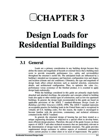
The most common method of determining lateral soil loads on residentialfoundations follows Rankine’s (1857) theory of earth pressure and uses what isknown as the Equivalent Fluid Density (EFD) method. As shown in figure 3.1,pressure distribution is assumed to be triangular and to increase with depth.In the EFD method, the soil unit weight w is multiplied by an empirical coefficient Ka toaccount for the soil is not actually fluid and the pressure distribution is not necessarilytriangular. The coefficient Ka is known as the active Rankine pressure coefficient. The EFD isdetermined as shown in equation 3.5-1.Equation 3.5-1FIGURE 3.1q KawTriangular Pressure Distribution on a Basement FoundationWallFor the triangular pressure distribution shown in figure 3.1, the pressure, P inpsf, at depth, h in feet, is determined by equation 3.5-2, and the resultant force, H inlbs, at depth, h in feet, is determined by equation 3.5-3. The factor q is the EFD asdiscussed above.Residential Structural Design Guide3-9
P qhEquation 3.5-2The total active soil force (pounds per linear foot of wall length) is—Equation 3.5-3H where11(qh )(h ) qh 222h the depth of the unbalanced fill on a foundation wallH the resultant force (plf) applied at a height of h/3 from the base of theunbalanced fill because the pressure distribution is assumed to be triangularThe EFD method is subject to judgment as to the appropriate value of thecoefficient Ka. The values of Ka in table 3.6 are recommended for the determinationof lateral pressures on residential foundations for various types of backfill materialsplaced with light compaction and good drainage. Given the long-time use of a 30pounds per cubic foot (pcf) EFD in residential foundation wall prescriptive designtables (ICC, 2012), the values in table 3.6 may be considered somewhat conservativefor typical conditions. A relatively conservative safety factor of 3 to 4 is typicallyapplied to the design of unreinforced or nominally reinforced masonry or concretefoundation walls (ACI, 2011). Therefore, at imminent failure of a foundation wall, the30 psf design EFD would correspond to an active soil lateral pressure determined byusing an EFD of about 90 to 120 pcf or more. The design examples in chapter 4demonstrate the calculation of soil loads.TABLE 3.6Values of Ka , Soil Unit Weight, and Equivalent FluidDensity by Soil Type1,2,3Type of Soil4(Unified Soil Classification)Sand or gravel (GW, GP, GM, SW, SP)Silty sand, silt, and sandy silt (GC, SM)Clay-silt, silty clay (SM-SC, SC, ML, MLCL)Clay5 (CL, MH, CH)Active PressureCoefficient (Ka)0.260.350.45Soil UnitWeight (pcf)115100100Equivalent FluidDensity (pcf)3035450.6010060Notes:1Values are applicable to well-drained foundations with less than 10 feet of backfill placed with light compaction or natural settlement, as iscommon in residential construction. The values do not apply to foundation walls in flood-prone environments; in such cases, an equivalent fluiddensity value of 80 to 90 pcf would be more appropriate (HUD, 1977).2Values are based on the Standard Handbook for Civil Engineers, 3rd ed. (Merritt, 1983), and on research on soil pressures reported in ThinWall Foundation Testing, Department of Civil Engineering, University of Alberta, (March 1992). The designer should note that the values forsoil equivalent fluid density differ from those recommended in ASCE 7-10 but are nonetheless compatible with current residential buildingcodes, design practice, and the stated references.3These values do not consider the significantly higher loads that can result from expansive clays and the lateral expansion of moist, frozen soil.Such conditions should be avoided by eliminating expansive clays adjacent to the foundation wall and providing for adequate surface andfoundation drainage.4Organic silts and clays and expansive clays are unsuitable for backfill material.5Backfill in the form of clay soils (non-expansive) should be used with caution on foundation walls with unbalanced fill heights greater than 3to 4 feet and on cantilevered foundation walls with unbalanced fill heights greater than 2 to 3 feet.Residential Structural Design Guide3-10
Depending on the type and depth of backfill material and the manner of itsplacement (see table 3.7), common practice in residential construction is to allow thebackfill soil to consolidate naturally by providing an additional 3 to 6 inches of fillmaterial. The additional backfill ensures that surface water drainage away from thefoundation remains adequate (that is, the grade slopes away from the building). It alsohelps avoid heavy compaction that could cause undesirable loads on the foundationwall during and after construction. If soils are heavily compacted at the groundsurface or compacted in lifts to standard Proctor densities greater than approximately85 percent of optimum (ASTM, 2012), the standard 30 pcf EFD assumption may beinadequate. In cases in which the backfill supports exterior slabs, patios, stairs, orother items, however, some amount of compaction is required unless the structuresare supported on a separate foundation bearing on undisturbed ground.Some remediation may be necessary in areas that contain marine clay or other expansive soils.In very moist conditions, these soils can place significant lateral loads against foundationwalls. The soils may need to be replaced with soil of lower clay content or the moisture levelsmust be stabilized to reduce excessive lateral pressures.TABLE 3.7Lateral Soil LoadDescription of Backfill Material3Well-graded, clean gravels; gravel-sand mixesPoorly graded clean gravels; gravel-sand mixesSilty gravels; poorly graded gravel-sand mixesClayey gravels; poorly graded gravel-clay mixesWell-graded, clean sands; gravelly sand mixesPoorly graded clean sands; sand-gravel mixesSilty sands; poorly graded sand-silt mixesSand-silt clay mix with plastic finesClayey sands; poorly graded sand-clay mixesInorganic silts; clayey siltsInorganic silt-clay mixesInorganic clays of low to medium plasticityOrganic silts and silt clays of low plasticityInorganic clayey silts; elastic siltsInorganic clays of high plasticityUnified MHCHDesign Lateral Soil Load1 (poundper square foot per foot of depth)Active Pressure At-Rest 06010060100222222Notes:1Design lateral soil loads are given for moist conditions for the specified soils at their optimum densities. Actual field conditions shall govern.2Unsuitable as backfill material3The definition and classification of soil materials is in accordance with ASTM D2487.Residential Structural Design Guide3-11
3.6 Wind Loads3.6.1GeneralWind produces dynamic loads on a structure at highly variable magnitudes.The variation in pressures at different locations on a building is complex to the pointthat pressures may become too analytically intensive for precise consideration indesign. Wind load specifications attempt to simplify the design problem byconsidering basic static pressure zones on a building representative of peak loads thatare likely to be experienced. The peak pressures in one zone for a given winddirection may not, however, occur simultaneously with peak pressures in other zones.For some pressure zones, the peak pressure depends on a narrow range of winddirections; therefore, the wind directionality effect must also be factored intodetermining risk-consistent wind loads on buildings. Characteristics of the buildingsite and the surrounding area, such as exposure and topography, also play a large rolein determining the peak pressures on the structure and should be carefully considered.In fact, most modern wind load specifications account for wind directionality andother effects in determining nominal design loads in some simplified form (ASCE,2010). This section further simplifies wind load design specifications to provide aneasy yet effective approach for designing typical residential buildings.Because they vary substantially over the surface of a building, wind loads areconsidered at two different scales. On a large scale, the loads produced on the overallbuilding are resisted by a system of structural elements working together to transferthe wind loads acting on the entire structure to the ground, a system known as themain wind force-resisting system (MWFRS). The MWFRS of a home includes theshear walls and diaphragms that create the lateral force-resisting system (LFRS) aswell as the structural systems, such as trusses, that experience loads from external andinternal pressures generated on the building. The wind loads applied to the MWFRSaccount for the area-averaging effects of time-varying wind pressures on the surfaceor surfaces of the building.Wind pressures are greater on certain localized surface areas of the building,particularly near abrupt changes in building geometry (for example, eaves, ridges, andcorners). Those higher wind pressures can occur on smaller areas, particularlyaffecting the loads carried by components and cladding (for example, sheathing,windows, doors, purlins, and studs). The components and cladding (C&C) transferlocalized time-varying loads to the MWFRS, at which point the loads average outboth spatially and temporally since, at a given time, some components may be at nearpeak loads while others are at substantially less than peak.In light-framed wood structural systems, the distinction between MWFRS andC&C is not as clear-cut as in other buildings. In some cases, structural componentsmay act as MWFRS and as C&C, depending on situations. The designer mustconsider which elements of the building must be treated as C&C, part of theMWFRS, or both. As indicated, parts of the MWFRS that collect and transfer lateralloads in shear walls and floors or roof diaphragms consist of wall studs, sheathing,Residential Structural Design Guide3-12
and trusses, and these elements as a system must be designed for MWFRS lateralloads; but the studs, sheathing, and truss chords must be designed for the directloading from wind as C&C. Thus, the stud size and connection to top and bottomplates must be designed for C&C pressures, yet the entire wall system, especially thesheathing thickness and the nailing attachment of the sheathing to the studs, must bedesigned to resist the shear forces created by the lateral loads.The next section presents a simplified method for determining both MWFRSand C&C wind loads. Because the loads in section 3.6.2 are determined for specificapplications, the calculation of MWFRS and C&C wind loads is implicit in the valuesprovided. Design example 3.2 in section 3.12
Residential Structural Design Guide 3-3 700 years, and this long return period provides a consistent risk basis for wind design across the country. Many elements of residential design continue to use ASD design level wind speeds, however, primarily because of how produc