Transcription
SE‐006 Design of Residential FoundationsInstructor: Ivan Jelic, Ph.D., P.E., LEED AP, MIStructE, CEngCourse ID: SE‐006PDH Hours: 8 PDHPDH Star T / F: (833) PDH‐STAR (734‐7827) E: info@pdhstar.com
CHAPTER 4Design of Foundations4.1 GeneralA foundation supports and anchors the superstructure of a building andtransfers all loads (including those from flood, wind, or seismic events) imposed on itdirectly to the ground. Foundations distribute the loads to the earth over an adequatearea so that loads do not exceed the bearing capacity of the soil and so that lateralmovement or settlement is minimized. In cold climates, the bottom of the foundationmust be below the frost line to prevent freeze-thaw damage and frost heave of thefooting.A foundation in residential construction may consist of a footing, wall, slab,pier, pile, or a combination of these elements. This chapter addresses the followingfoundation types— Crawl space.Basement.Slab-on-grade with stem wall.Monolithic slab.Piles.Piers.Alternative methods.As discussed in chapter 1, the most common residential foundation materialsare cast-in-place concrete and concrete masonry (that is, concrete block).Preservative-treated wood, precast concrete, and other materials may also be used.The concrete slab-on-grade is a prevalent foundation type in the South andSouthwest; basements are the most common type in the East and Midwest. Crawlspaces are common in the Northwest and Southeast. Pile foundations designed tofunction after being exposed to scour and erosion are commonly used in coastal floodzones to elevate structures above flood levels. Piles also are used in weak orResidential Structural Design Guide4-1
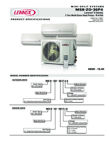
expansive soils to reach a stable stratum and on steeply sloped sites. Figure 4.1depicts different foundation types; a brief description follows.A crawl space is a building foundation that uses a perimeter foundation wallto create an underfloor space that is not habitable; the interior crawl space elevationmay or may not be below the exterior finish grade. In mapped flood plains, a crawlspace that has the interior grade below the exterior grade on all sides is considered abasement. A basement typically is defined as a portion of a building that is partly orcompletely below the exterior grade and that may be used as habitable space, asstorage space, or for parking. The primary difference between a basement and a crawlspace is height (basements usually are taller). The floors of basements usually arefinished, and the interiors frequently are finished. The wall height is sometimesdetermined by the depth of the footing required for frost protection.A slab-on-grade with an independent stem wall is a concrete floor supportedby the soil independently of the rest of the building. The stem wall supports thebuilding loads and in turn is supported directly by the soil or a footing. A monolithicor thickened-edge slab is a ground-supported slab-on-grade with an integral footing(that is, a thickened edge); it is normally used in warmer regions that have little or nofrost depth but is also used in colder climates when adequate frost protection isprovided (see section 4.7).When necessary, piles are used to transmit the load to a deeper soil stratumwith a higher bearing capacity to prevent failure from undercutting of the foundationby scour from flood water flow at high velocities and to elevate the building aboverequired flood elevations. Piles also are used to isolate the structure from expansivesoil movements.Pier and beam foundations can provide an economical alternative to crawlspace perimeter wall construction. A common practice is to use a brick curtain wallbetween piers for appearance and bracing.The design procedures and information in this chapter cover the followingtopics. Foundation materials and properties.Soil-bearing capacity and footing size.Concrete or gravel footings.Concrete and masonry foundation walls.Preservative-treated wood walls.Insulating concrete foundations.Concrete slabs on grade.Pile foundations.Frost protection.Concrete design procedures generally follow the strength design methodcontained in the American Concrete Institute’s ACI 318 (ACI, 2011) although certainaspects of the procedures may be considered conservative relative to conventionalresidential foundation applications. For this reason, this guide provides supplementaldesign guidance when practical and technically justified. ACI 332 (ACI, 2010), whichcontains design provisions and guidance specific to residential construction, isResidential Structural Design Guide4-2
referenced in the International Residential Code (IRC) as an alternative to theconventional foundation requirements of the code or the design procedures of ACI318. Masonry design procedures follow the allowable stress design (ASD) method ofThe Masonry Society’s TMS 402 (TMS, 2011). Wood design procedures are used todesign the connections between the foundation system and the structure above andfollow the ASD method for wood construction (see chapter 7 for connection designinformation). In addition, the designer is referred to the applicable design standardsfor symbol definitions and additional guidance because the intent of this chapter is toprovide supplemental instruction in the efficient design of residential foundations.To maintain consistency, this guide uses the load and resistance factor design(LRFD) load combinations that were used in chapter 3, which are also those specifiedin the American Society of Civil Engineers’ ASCE 7. There may be some minorvariations in those required in ACI 318 for strength design of concrete. The purposeof this guide is to provide designs that are at least consistent with current residentialbuilding code and construction practice. With respect to the design of concrete inresidential foundations, the guide seeks to provide reasonable safety margins thatmeet or exceed the minimums required for other, more crucial requirements of ahome—namely, the safety of lives. The designer is responsible for ensuring that thedesign meets the building code requirements and will be approved by the buildingofficial.Residential Structural Design Guide4-3
FIGURE 4.1Types of FoundationsResidential Structural Design Guide4-4
4.2 Material PropertiesA residential designer using concrete and masonry materials must have a basicunderstanding of such materials, including variations in the materials’ compositionand structural properties. In addition, a designer must take into consideration soils,which are also considered a foundation material (Section 4.3 provides information onsoil bearing). A brief discussion of the properties of concrete and masonry follows.4.2.1ConcreteThe concrete compressive strength (fc') used in residential construction istypically either 2,500 or 3,000 pounds per square inch (psi), although other valuesmay be specified. For example, 4,000 psi concrete may be used for improvedweathering resistance in particularly severe climates or unusual applications. Theconcrete compressive strength may be verified in accordance with the AmericanSociety for Testing and Materials’ ASTM C39 (ASTM, 2012c). Given that the rate ofincrease in concrete strength diminishes with time, the specified compressive strengthusually is associated with the strength attained after 28 days of curing time, when theconcrete attains about 85 percent of its fully cured compressive strength.Concrete is a mixture of cement, water, and sand, gravel, crushed rock, orother aggregates. Sometimes one or more admixtures are added to change certaincharacteristics of the concrete, such as workability, durability, and time of hardening.The proportions of the components determine the concrete mix’s compressivestrength and durability.TypePortland cement is classified into several types, in accordance with ASTMC150 (ASTM, 2012b). Residential foundation walls typically are constructed withType I cement, which is a general-purpose Portland cement used for the vast majorityof construction projects. Other types of cement are appropriate in accommodatingconditions related to heat of hydration in massive pours and sulfate resistance. Insome regions, sulfates in soils have caused durability problems with concrete. Thedesigner should check into local conditions and practices.WeightThe weight of concrete varies depending on the type of aggregates used in theconcrete mix. Concrete typically is classified as lightweight or normal weight. Thedensity of unreinforced normal weight concrete ranges between 144 and 156 poundsper cubic foot (pcf) and typically is assumed to be 150 pcf. Residential foundationsusually are constructed with normal weight concrete.Residential Structural Design Guide4-5
SlumpSlump is the measure of concrete consistency; the higher the slump, the wetterthe concrete and the easier it flows. Slump is measured in accordance with ASTMC143 (ASTM, 2012d) by inverting a standard 12-inch-high metal cone, filling it withconcrete, and then removing the cone; the amount the concrete that settles in units ofinches is the slump. Most foundations, slabs, and walls consolidated by hand methodshave a slump between 4 and 6 inches. One problem associated with a high-slumpconcrete is segregation of the aggregate, which leads to cracking and scaling.Therefore, a slump of greater than 6 inches should be avoided. Adding water lowersthe strength while improving workability, so the total amount of water in the concreteshould be carefully monitored and controlled. Admixtures used during extremely coldor hot weather placement (or for other reasons) may change the slump.Weather ResistanceConcrete is largely weather resistant. When concrete may be subjected tofreezing and thawing during construction, however, or when concrete is located inregions prone to extended periods of freezing, additional measures must be taken.Those requirements can be found in the IRC (ICC, 2012), and include air entrainmentand increased minimum compressive strength requirements.AdmixturesAdmixtures are materials added to the concrete mix to improve workabilityand durability and to retard or accelerate curing. Some of the most commonadmixtures are described below. Water reducers improve the workability of concrete without reducing itsstrength.Retarders are used in hot weather to allow more time for placing andfinishing concrete. Retarders may also reduce the early strength ofconcrete.Accelerators reduce the setting time, allowing less time for placing andfinishing concrete. Accelerators may also increase the early strength ofconcrete.Air entrainers are used for concrete that will be exposed to freeze-thawconditions and deicing salts. Less water is needed and segregation ofaggregate is reduced when air entrainers are added.Residential Structural Design Guide4-6
ReinforcementConcrete has high compressive strength but low tensile strength; therefore,reinforcing steel often is embedded in the concrete to provide additional tensilestrength and ductility. In the rare event that the capacity is exceeded, the reinforcingsteel begins to yield, thereby preventing an abrupt failure that may otherwise occurwith plain, unreinforced concrete. For this reason, a larger safety margin is used in thedesign of plain concrete construction than in reinforced concrete construction.Steel reinforcement is available in grade 40 or grade 60; the grade numberrefers to the minimum tensile yield strength (fy) of the steel (i.e., grade 40 is aminimum 40 thousand pounds per square inch [ksi] steel and grade 60 is a minimum60 ksi steel). Either grade may be used for residential construction; however, moststeel reinforcement in the U.S. market today is grade 60. The concrete mix, or slump,must be adjusted by adding the appropriate amount of water to allow the concrete toflow easily around the reinforcement bars, particularly when the bars are closelyspaced or are crowded at points of overlap. Close rebar spacing rarely is required inresidential construction, however, and should be avoided in design if at all possible.The most common steel reinforcement or rebar sizes in residentialconstruction are No. 3, No. 4, and No. 5, which correspond to diameters of 3/8 inch,1/2 inch, and 5/8 inch, respectively. The bar designations indicate the bar size in 1/8inch increments. These three sizes of rebar are easily manipulated at the jobsite byusing manual bending and cutting devices. Table 4.1 shows useful relationshipsbetween the rebar number, diameter, and cross-sectional area for reinforced concreteand masonry design.Fiber reinforcement is being used in some concrete slab installation. The fibercould be steel, natural, or synthetic. It helps (1) improve resistance to freeze-thaw, (2)increase resistance to some spalling of the surface, (3) control cracking, and (4)improve the concrete’s shatter resistance. Fibers generally do not increase thestructural strength of the concrete slab and do not replace normal reinforcing barsused for tensile strength.TABLE 4.1Rebar Size, Diameter, and Cross-Sectional AreasSizeDiameter (inches)Area (square inches)No. 33/80.11No. 41/20.20No. 55/80.31No. 63/40.44No. 77/80.60No. 810.79Residential Structural Design Guide4-7
4.2.2Concrete Masonry UnitsConcrete masonry units (CMUs), commonly referred to as concrete blocks, arecomposed of Portland cement, aggregate, and water. In some situations, CMUs mayalso include admixtures. Low-slump concrete is molded and cured to produce strongblocks or units. Residential foundation walls typically are constructed with units 7 5/8inches (nominal 8 inches) high by 15 5/8 inches (nominal 16 inches) long, providinga 3/8-inch allowance for the width of mortar joints. Nominal 8- and 12-inch-thickCMUs are readily available for use in residential construction.TypeASTM C90 (ASTM, 2013) requires that the minimum average design strength(f'm) of standard CMUs be 1,900 psi, with no individual unit having a compressivestrength of less than 1,700 psi. Higher strengths also may be specified if required bydesign. The ASTM classification includes two types. Type II is a non-moisturecontrolled unit and is the type typically used for residential foundation walls.WeightCMUs are available with different densities by altering the type(s) ofaggregate used in their manufacture. CMUs typically are referred to as lightweight,medium weight, or normal weight, with respective unit weights or densities of lessthan 105 pcf, between 105 and 125 pcf, and more than 125 pcf. Residentialfoundation walls typically are constructed with low- to medium-weight units becauseof the low compressive strength required. Lower density units are generally moreporous, however, and must be properly protected to resist moisture intrusion. Acommon practice in residential basement foundation wall construction is to provide acement-based parge coating and a brush- or spray-applied bituminous coating on thebelowground portions of the wall. Section R406 in the IRC provides the prescriptiverequirements for parging and damp-proofing or waterproofing foundation walls thatretain earth and enclose interior spaces. The parge coating is not required for concretefoundation wall construction.Hollow or SolidCMUs are classified as hollow or solid in accordance with ASTM C90. Thenet concrete cross-sectional area of most CMUs ranges from 50 to 70 percent,depending on unit width, face-shell and web thicknesses, and core configuration.Hollow units are defined as those in which the net concrete cross-sectional area is lessthan 75 percent of the gross cross-sectional area. Solid units are not necessarily solidbut are defined as those in which the net concrete cross-sectional area is 75 percent ofthe gross cross-sectional area or greater.Residential Structural Design Guide4-8
MortarMasonry mortar is used to join CMUs into a structural wall; it also retards airand moisture infiltration. The most common way to lay block is in a running bondpattern, in which the vertical head joints between blocks are offset by half the blocklength from one course to the next. Mortar is composed of water, cement, lime, andclean, well-graded sand, and water and is typically classified into types M, S, N, O,and K, in accordance with ASTM C270 (ASTM, 2012a). Residential foundation wallstypically are constructed with type M or type S mortar, both of which are generallyrecommended for load-bearing interior and exterior walls, including above- andbelow-grade applications.GroutGrout is a slurry consisting of cementitious material, aggregate, and water.When needed, grout commonly is placed in the hollow cores of CMUs to provide awall with added strength. In reinforced load-bearing masonry wall construction, groutis usually placed only in those hollow cores containing steel reinforcement. The groutbonds the masonry units and steel so that they act as a composite unit to resistimposed loads. Grout may also be used in unreinforced concrete masonry walls foradded strength. The IRC requires grouted cells at foundation sill and sole plate anchorbolt locations, regardless of whether the masonry wall is otherwise reinforced.4.3 Soil-Bearing Capacityand Footing SizeSoil-bearing investigations rarely are required for residential constructionexcept when a history of local problems provides evidence of known risks (forexample, organic deposits, landfills, expansive soils, and seismic risk). Soil-bearingtests on stronger-than-average soils can, however, justify using smaller footings oreliminating footings entirely if the foundation wall provides sufficient bearingsurface. Table 4.2 provides a conservative relationship between soil type and loadbearing value. A similar table is published in the building codes (table R401.4.1 in theIRC). These presumptive soil-bearing values, however, should be used only when thebuilding codes do not require geotechnical investigation reports (section R401.4,IRC).Residential Structural Design Guide4-9
TABLE 4.2Presumptive Soil-Bearing Values by Soil DescriptionPresumptive Load-BearingValue (psf)Soil Description1,500Clay, sandy clay, silty clay, clayey silt, silt, and sandy silt2,000Sand, silty sand, clayey sand, silty gravel, and clayey gravel3,000Gravel and sandy gravel4,000Sedimentary and foliated rock12,000Crystalline bedrockpsf pounds per square foot.Source: ICC (2012).When a soil-bearing investigation is desired to determine more accurate andeconomical footing requirements, the designer commonly turns to ASTM D1586,Standard Penetration Test (SPT) and Split-Barrel Sampling of Soils (ASTM, 2011).This test relies on a 2-inch-diameter device driven into the ground with a 140-poundhammer dropped from a distance of 30 inches. The number of hammer drops orblows needed to create a 1-foot penetration (blow count) yields values that can beroughly correlated to soil-bearing values, as shown in Table 4.3. The instrumentationand cost of conducting the SPT usually are not warranted for typical residentialapplications. Nonetheless, the SPT method provides information on deeper soil strataand thus can offer valuable guidance for foundation design and building location,particularly when subsurface conditions threaten to be problematic. The values inTable 4.3 are associated with the blow count from the SPT method. Many engineerscan provide reasonable estimates of soil bearing by using smaller penetrometers atlower cost, although such devices and methods may require an independentcalibration to determine presumptive soil-bearing values and may not be able todetect deep subsurface problems. Calibrations may be provided by the manufactureror, alternatively, developed by the engineer.In addition to ASTM D1586, the Dynamic Cone Penetrometer (DCP) test(Burnham and Johnson, 1993), has gained widespread use as a more economicalalternative with equivalent accuracy. In this handheld test, a metal cone is driven intothe ground by repeatedly striking it with a 17.6-pound (8-kilogram) weight, droppedfrom a distance of 2.26 feet (575 millimeters). Penetration of the cone is measuredafter each blow; the blow count per 1 3/4-inch penetration is approximatelyequivalent to the SPT blow count provided in table 4.3.The designer should exercise judgment when selecting the final design valueand be prepared to make adjustments (increases or decreases) in interpreting andapplying the results to a specific design. The values in tables 4.2 and 4.3 generally areassociated with a safety factor of 3 (Naval Facilities Engineering Command, 1986)and are considered appropriate for noncontinuous or independent spread footingssupporting columns or piers (that is, point loads). Use of a safety factor could beResidential Structural Design Guide4-10
considered for smaller structures with continuous spread footings, such as houses, orstructures for which ultimate (LRFD) values are used for design loads. Thepresumptive values in Table 4.3—or as modified as described previously—areintended to be used with the ASD load combinations in chapter 3. If LRFD (strength)design load combinations are used, then the presumptive values should beadditionally adjusted (that is, divided by the maximum load factor in the loadcombination considered, usually a factor of 1.6 for live or snow loads).Presumptive Soil-Bearing Values (psf) Based on StandardPenetrometer Blow CountTable 4.3Noncohesive SoilsIn Situ Consistency, N1FirmCompact(10 to 25 blows per (25 to 50 blows perfoot)foot)Gravel4,000 (10)8,000 (25)11,000 (50)Sand2,500 (6)5,000 (20)6,000 (35)Fine sand1,000 (5)3,000 (12)5,000 (30)500 (5)2,000 (15)4,000 (35)SiltIn Situ Consistency, N :1CohesiveSoilsLoose2(5 to 10 blows perfoot)Soft3(3 to 5 blows perfoot)Medium(about 10 blowsper foot)Stiff(more than 20blows per foot)Clay, sand, gravel mixtures2,000 (3)5,000 (10)8,000 (20)Sandy or silty clay1,000 (4)3,000 (8)6,000 (20)2,000 (10)4,000 (25)Clay500 (5)Source: Naval Facilities Engineering Command, 1986.psf pounds per square foot.N denotes the standard penetrometer blow count in blows per foot, in accordance with ASTM D1586; shown in parentheses.Compaction should be considered in these conditions, particularly when the blow count is five blows per foot or less.3Pile and grade beam foundations should be considered in these conditions, particularly when the blow count is five blows per foot or less.12The required width or area of a spread footing is determined by dividing thebuilding load on the footing by the soil-bearing capacity from table 4.2 or table 4.3, asshown below. Building design loads, including dead and live loads, should bedetermined in accordance with chapter 3 by using ASD load combinations.Residential Structural Design Guide4-11
Areaindependent spreadWidthcontinuousfootingfooting Load in lbsSoil bearing capacity in psfLoad , lb per linear foot ( plf )Soil bearing capacity in psf4.4 FootingsThe objectives of footing design are— To provide a level surface for construction of the foundation wall.To provide adequate transfer and distribution of building loads to theunderlying soil.To provide adequate strength, in addition to the foundation wall, toprevent differential settlement of the building in weak or uncertain soilconditions by bridging those poor soil conditions.To place the building foundation at a sufficient depth to avoid frostheave or thaw weakening in frost-susceptible soils and to avoidorganic surface soil layers.To provide adequate anchorage or mass (when needed in addition tothe foundation wall) to resist potential uplift, sliding, and overturningforces resulting from high winds or severe seismic events.This section presents design methods for concrete and gravel footings. Thedesigner must first establish the required footing width in accordance with section4.3. Further, if soil conditions are stable or the foundation wall can adequatelyresist potential differential settlement, the footing may be completely eliminated.By far, the most common footing in residential construction is acontinuous concrete spread footing; however, concrete and gravel footings areboth recognized in prescriptive footing size tables in residential building codes formost typical conditions (ICC, 2012). In contrast, special conditions give rise toengineering concerns that must be addressed to ensure the adequacy of anyfoundation design. Special conditions include— Steeply sloped sites requiring a stepped footing.High wind conditions.Inland or coastal flooding conditions.High-hazard seismic conditions.Poor soil conditions.Residential Structural Design Guide4-12
4.4.1Simple Gravel and Concrete Footing DesignBuilding codes for residential construction contain tables that prescribeminimum footing widths for plain concrete footings (ICC, 2012). Alternatively,footing widths may be determined in accordance with section 4.3, based on asite’s particular loading condition and presumptive soil-bearing capacity. Thefollowing are general rules of thumb for determining the thickness of plainconcrete footings for residential structures, once the required bearing width hasbeen calculated. The minimum footing thickness should not be less than the distancethe footing extends outward from the edge of the foundation wall or 6inches, whichever is greater.The footing width should project a minimum of 2 inches from bothfaces of the wall (to allow for a minimum construction tolerance) butnot greater than the footing thickness.These rules of thumb generally result in a footing design that differssomewhat from the plain concrete design provisions of chapter 22 of ACI 318.Footing widths generally follow the width increments of standard excavationequipment (in other words, a backhoe bucket size of 12, 16, or 24 inches).Although longitudinal steel reinforcement is not always required for residentialscale structures in typical soil conditions, the designer should consider addingsome (two No. 4 or No. 5 bars is common) to avoid possible footing crackingwhere soil consolidation or a loss of soil-bearing capacity can occur. Forsituations in which the rules of thumb or prescriptive code tables do not apply orin which a more economical solution is possible, a more detailed footing analysismay be considered (see section 4.4.2). Example 4.1 in section 4.9 illustrates aplain concrete footing design in accordance with the simple method describedherein.Much like a concrete footing, a gravel footing may be used to distributefoundation loads to a sufficient soil-bearing surface area. A gravel footingprovides a continuous path for water or moisture and thus must be drained inaccordance with the foundation drainage provisions of the IRC. Gravel footingsare constructed of crushed stone or gravel that is consolidated by tamping orvibrating. Pea gravel, which is naturally consolidated, does not requirecompaction and can be screeded to a smooth, level surface, much like concrete.Although typically associated with pressure-treated wood foundations (refer tosection 4.5.3), a gravel footing can support cast-in-place or precast concretefoundation walls.The size of a gravel footing usually is based on a 30- to 45-degree angle ofrepose for distributing loads; therefore, as with plain concrete footings, therequired depth and width of the gravel footing depends on the width of thefoundation wall, the foundation load, and soil-bearing values. Following a rule ofthumb similar to that for a concrete footing, the gravel footing thickness should beResidential Structural Design Guide4-13
no less than 1.5 times its extension beyond the edge of the foundation wall or, inthe case of a pressure-treated wood foundation, the mud sill. Just as with aconcrete footing, the thickness of a gravel footing may be considered in meetingthe required frost depth. In soils that are not naturally well drained, provisionshould be made to adequately drain a gravel footing.4.4.2Concrete Footing DesignFor many residential footing designs, prescriptive and conventionalresidential footing requirements found in residential building codes andconstruction guides are adequate, if not conservative. Concrete design forresidential construction is covered in ACI 332 Residential Code Requirements forStructural Concrete (ACI, 2010). To improve performance and economy or toaddress peculiar conditions, however, a footing may need to be speciallydesigned. Many floor plans in today’s residential buildings are partially open andfrequently create nonuniform loading conditions on load-bearing walls andfootings. These nonuniform load conditions must be considered in the design offootings, and reliance on strictly prescriptive methods of design is not always asound design decision.A footing is designed to resist the upward-acting pressure created by thesoil beneath the footing; that pressure tends to make the footing bend upward atits edges. According to ACI 318, the three modes of failure considered inreinforced concrete footing design are one-way shear, two-way shear, and flexure(see figure 4.2). Bearing (crushing) is also a possible failure mode but is rarelyapplicable to residential loading conditions. To simplify calculations for the threefailure modes, the following discussion explains the relation of the failure modesto the design of plain and reinforced concrete footings (Refer to ACI 318 foradditional commentary and guidance). The design equations used later in thissection are based on ACI 318 and principles of engineering mechanics, asdescribed herein. Moreover, the approach is based on the assumption of uniformsoil-bearing pressure on the bottom of the footing; therefore, walls and columnsshould be supported as close as possible to the center of the footings.One-Way (Beam) ShearWhen a footing fails due to one-way (beam) shear, the failure occurs at anangle approximately 45 degrees to the wall, as shown in figure 4.2. For plainconcrete footings, the soil-bearing pressure has a negligible effect on the diagonalshear tension for distance t from the wall edge toward the footing
Residential Structural Design Guide 4-3 referenced in the International Residential Code (IRC) as an alternative to the conventional foundation requirements of the code or the design procedures of ACI 318. Masonry design procedures follow the allowable stress design (