Transcription
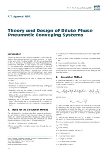
Conveying Shape and Features with Image-Based RelightingDavid Akers Stanford UniversityFrank Losasso Stanford UniversityJeff Klingner Stanford UniversityJohn Rick†Stanford UniversityPat Hanrahan Stanford UniversityManeesh Agrawala Microsoft ResearchAbstractHand-crafted illustrations are often more effective than photographsfor conveying the shape and important features of an object, butthey require expertise and time to produce. We describe an imagecompositing system and user interface that allow an artist to quicklyand easily create technical illustrations from a set of photographs ofan object taken from the same point of view under variable lightingconditions. Our system uses a novel compositing process in whichimages are combined using spatially-varying light mattes, enablingthe final lighting in each area of the composite to be manipulatedindependently. We describe an interface that provides for the painting of local lighting effects (e.g. shadows, highlights, and tangentiallighting to reveal texture) directly onto the composite. We surveysome of the techniques used in illustration and lighting design toconvey the shape and features of objects and describe how our system can be used to apply these techniques.CR Categories: I.3.4 [Computer Graphics]: Graphics Utilities—Paint Systems; I.3.6 [Computer Graphics]: Methodology andTechniques—Interaction Techniques; I.3.8 [Computer Graphics]:Applications; J.2 [Physical Sciences and Engineering]: ArchaeologyKeywords: Visualization, Relighting, Image Composition, Scientfic Illustration, Technical Illustration, Photography, LightingDesign1IntroductionAlgorithms for lighting simulation have continued to improve in recent years. Lighting design, however, remains a big problem. Anapplication where good lighting design is important is technical illustration. The example of a human skull shown at the top of Figure 1 is from the Guild Handbook on Scientific Illustration [Hodges1989]. The illustration on the right does a better job of depicting theform and important features of the skull than the photograph on theleft. One reason for its effectiveness is its careful use of lighting. dakers losasso klingner maneesh hanrahan@graphics.stanford.edu† johnrick@stanford.eduFigure 1: Above: A photograph of a human skull, followed by anartist’s handmade drawing of the same skull [Hodges 1989]. Arrows in the drawing indicate variance in the local lighting directionthat the artist used to emphasize the shape and texture of the skull.Below: A photograph of a baboon skull, followed by a compositeimage we generated from a set of many photographs taken underdifferent lighting directions. (Top row images are used by permission of John Wiley & Sons, Inc.)Lighting can be used to convey: Orientation: On smooth portions of a curved surface, directional light is used to create diffuse shading, which helpsviewers estimate the local orientation of the surface and differentiate between convex and concave parts of the shape. Curvature: Regions with high curvature or edge discontinuities are often emphasized with highlights. Photographers depict metallic objects using linear lights, aligning highlightswith directions of zero curvature. Bumps and texture: Small-scale surface features are mucheasier to detect under side or raking lighting. Shadows castby these features create regions of high contrast and revealtexture. The best landscape photographs are often taken atdawn or dusk; the best views of the moon’s craters occur alongits terminator [Koenderink and Pont 2002]. Silhouettes: The silhouette of an object is one of its most distinctive features. Rim lighting is often used along the edge ofan object to distinguish it from a dark background. Rim shadowing serves the same purpose against a light background.
Since conveying shape and form is a primary goal of illustration,illustrators are generally not concerned with physically accuratelighting. In fact, to a photographer or illustrator, real-world lightingoften has unintended side effects: Over- and under-exposure: A well-lit photograph has uniform exposure and good contrast. Achieving both of thesegoals is difficult in practice, particularly in natural environments that exhibit a high dynamic range. Shadows: While they provide useful cues of relative position,shadows often hide important details. Moreover, their umbraland penumbral boundaries can be distracting. The illustrationof the human skull in Figure 1 has fewer shadows than thephotograph. Distracting highlights: Shiny objects often have distractinghighlights in confusing positions. For example, anthropologists have reported great difficulty in photographing obsidiantools because of their high specularity [Rick and White 1975].Any photographer or illustrator knows that lighting design is a hardproblem. The lights are carefully controlled in a photographer’s studio or on a motion picture set. Photographers often think of lightsin terms of their effects or purposes (e.g. key light, rim light, etc.).In Figure 1, the arrows in the human skull diagram on the rightindicate how the illustrator used lighting to emphasize the important aspects of the skull. Diagrams like this are often used to teachillustrators and photographers how to use lighting effectively.In this paper, we describe a simple interactive tool to producetechnical illustrations from a collection of photographs of an object, each taken under a different lighting environment. These photographs are combined using spatially-varying light mattes to determine the final lighting for different regions of the composite. Theinterface provides a convenient set of tools that allow an artist tocombine photographs to create high quality illustrations like that ofthe human skull shown in Figure 1. It should be noted that our goalis not physical accuracy, even though our composite images oftenappear realistic. As with many scientific illustration techniques, wesacrifice physical accuracy in order to effectively convey the shapeand features of an object.We have been working with anthropologists who often need toproduce well-lit depictions of artifacts for publication. Currently,this involves one of two labor-intensive processes: either solvingthe difficult traditional lighting-design problem for photography,or producing handmade illustrations. Our system allows users toquickly produce photographic illustrations with far less effort orartistic skill.2Related WorkThe goals and techniques of cinematic lighting design are discussedin detail in books on photography [Adams 1999; London and Upton 1997], film [Alton 1995] and stage lighting [Millerson 1991].Calahan [2000] has summarized this classic work and practice inthe context of computer-generated imagery. In contrast, functionallighting design has different goals, such as the minimization ofglare or the even lighting of a work surface [Kaufman and Christensen 1984]. In this paper, we concentrate on using lighting designfor technical illustration and draw upon illustration manuals such asthe Guild Handbook discussed in the introduction [Hodges 1989].In computer graphics, lighting design tools are often based on inverse lighting algorithms. For example, it is possible to compute theintensities of light sources based on photographs of an object [Yuet al. 1999; Ramamoorthi and Hanrahan 2001]. Alternatively, a usercan paint the desired lighting qualities, and algorithms exist to solvefor the properties of a uniform area light source in a diffuse environment [Schoeneman et al. 1993; Kawai et al. 1993]. Techniquesare also available for controlling the position of lights by direct manipulation of shadows [Poulin and Fournier 1992; Pellacini et al.2002] and highlights [Poulin and Fournier 1992].One of the most important insights in relighting algorithms isthat light transport is linear. The image of a scene illuminated withmultiple sources may be computed by summing the images of thescene illuminated by each single source. Lighting design by digitally compositing multiple light images is a simple technique foradjusting light intensities and controlling the relative amount of diffuse and specular lighting. A variation that works for environmentmaps is to project the lighting onto a different basis, such as spherical harmonics [Nimeroff et al. 1994; Dobashi et al. 1995; Teo et al.1997; Sloan et al. 2002], or to compute the Principal ComponentAnalysis of the collection of images to form eigenlight images. Epstein et al. [1995] and Ramamoorthi [2002] have shown empiricallythat usually only a few images are needed to approximate any desired lighting. In all these linear techniques, the light images arecombined using a single weight per image; in this paper, we usespatially-varying weights.An important motivation for our approach is new technology forrapidly collecting a large number of images under different illumination conditions. This has been done using a robotically controlledlight source [Debevec et al. 2000], a set of electronically controlledflashes at selected points on a sphere [Georghiades et al. 2001; Debevec et al. 2002; Malzbender et al. 2001], or a set of handheld lightsources [Masselus et al. 2002]. The goal of these previous capturesystems has been to collect a set of images so that objects can be relit in real time [Malzbender et al. 2001] or using illumination froma natural environment [Debevec et al. 2000; Hawkins et al. 2001;Debevec et al. 2002].Finally, there are several recent papers that develop nonphotorealistic (NPR) lighting models for illustration. Gooch et al.[1998] describe a cool-to-warm shading model to produce picturesin the style of technical illustration. Sloan et al. [2001] introducedthe idea of the LIT sphere, an idealized environment map that produces simple, effective lighting effects. Hamel [2000] introduced acomponent-based lighting model that is based on ideas in the GuildHandbook. (See Strothotte and Schlechtweg [2002] for a nice discussion of this model.) Anderson and Levoy [2002] have also usedNPR lighting effects to illustrate unwrapped 3D scans of cuneiformtablets. Our approach is the first to produce NPR lighting effectswith linear basis images combined using spatially-varying weights.3 Relighting for IllustrationThis section describes our image composition technique and a noveluser interface that can be used to easily create illustrations that effectively convey the shape and features of an object.3.1Spatially Varying LightingOur system takes a set of photographs as input and produces a single composite image as output. The input images consist of photographs taken from the same point of view but with differing incident lighting directions. We associate each source photograph s iwith a matte image wi that modulates its contribution to the finalcomposite image at each pixel p(x, y). The n weighted source images are then added together to produce the final composite. Toensure that the composite photograph has the same average brightness as the input images, we require that the weights at each pixelsum to one. For each pixel p(x, y) in the composite image:p(x, y) n wi (x, y)si (x, y),i 1andn wi (x, y) 1i 1(1)
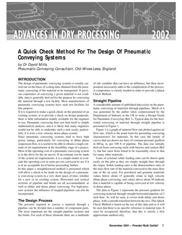
Figure 2: Three sample photographs of a baboon skull cast taken under different lighting conditions, shown above their corresponding mattes.The composite image is shown on the right. Arrows indicate local variation in the lighting direction across the resulting composite.After changing one of the weights wk (x, y) to wk 0 (x, y), we canrenormalize the sum by multiplying each of the n 1 remainingweights for that pixel by a single coefficient. Since the weightssum to one before the adjustment, we can perform this calculationincrementally by deriving this coefficient in terms of the old andnew weights of the kth image: 1 wk 0 (x, y)0wi (x, y) wi (x, y) i 6 k(2)1 wk (x, y)We clamp wk 0 to a value slightly less than one to preserve therelative proportions of the other weights for that pixel. This alsoprecludes the possibility of division by zero in Equation 2.Figure 2 illustrates the application of spatially-varying mattes toproduce a composite photograph of a baboon skull cast.3.2An Interactive ApplicationSince our input data typically consist of hundreds of photographs,creating composite photographs with them can be difficult using existing image manipulation tools. The challenges include navigatingthis large set of input images as well as updating and rendering thecomposite at interactive rates. To address these concerns, we havedeveloped an interactive application designed to make it easier toproduce effective technical illustrations using our technique. Figure 3 shows a labeled screen shot of our interface. Please see theincluded video footage for some examples of its use.3.2.1Painting InterfaceOur interface is built on a familiar painting paradigm, in which theartist uses a virtual airbrush to paint directly into the matte images associated with each photograph. The airbrush has severalattributes: light direction, brush size, and brush weight. A trackballinterface gives the artist the ability to choose any lighting directionon the sphere. Each direction selects a single original photograph,which is displayed to the side of the composite image. The brushaffects the matte for the currently selected photograph, implicitlymodifying all other non-zero mattes when the weights are renormalized. A gaussian falloff function is used to smoothly decrease theweight contributions across the width of the brush. A large brushsize gives the artist the ability to make sweeping changes to thecomposite photograph, while a small brush size allows for small,sharp changes (e.g. applying rim lighting around the silhouette ofthe object or removing small shadows or highlights that obscure important details.) Finally, the weight of the brush controls the rate atwhich virtual paint is deposited on the canvas.3.2.2Interpolating the Light DirectionSince the lighting direction is an attribute of the brush, painting canbecome tedious when the artist wants to change the light directionsmoothly across the composite. To address this, we provide a modein which it is possible to place 3D arrows directly onto the composite image, forming a vector field of lighting directions. Whenthe user applies a brush to the canvas in this mode, the lighting directions are interpolated across the extent of the brush according tothe vector field. The interpolated light direction at a pixel is computed by taking an average of all the vectors weighted by the inversesquare of their distance to that pixel. Figure 5 illustrates the use ofthis tool to create an illustration of the moon’s surface.3.2.3Environment MapsAs the mouse cursor is moved across the composite, the system displays the environment map for the pixel currently under the cursor.This map is displayed as a point rendering of a sphere, in whicheach point is color coded according to the amount of light comingfrom that direction. This is helpful in two ways: (1) it indicateswhich input photographs contribute to the composite at any givenpixel so that their corresponding mattes can be found quickly forediting, and (2) it gives a physical depiction of the lighting environment (as a set of point lights) for each region of the composite tohelp the user create desired local lighting effects.3.3ImplementationThe main challenge in the implementation of our system is processing the large number of input images that we use (typicallyhundreds). To enable the manipulation of the composites at an interactive rate, we make heavy use of graphics hardware acceleration. Each source image and matte is stored as a texture on thegraphics card and is loaded only when the matte contains non-zeroentries. Image composition is accomplished by modulating eachsource image with its associated matte using multi-texturing andthen combining the weighted slices using additive blending. Thisimplementation allows rendering to proceed in real time on consumer graphics hardware.Storing the matte textures separately from the source images(rather than as an alpha channel) allows us to represent the mattesat lower resolutions. Experimentation indicates that the mattes canbe represented at about 41 the resolution of the photographs without introducing artifacts in the composites. This greatly reduces thetime required to update the mattes as the artist paints.
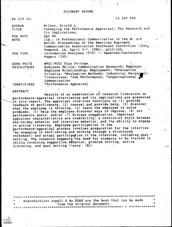
onmentmapCompositeControlsFigure 3: Our interactive painting system consists of two separate components: a composite window (left) and a controls window (right).The artist manipulates the light direction in the controls window to select a source photograph from the input dataset. The matte imagecorresponding to this source photograph is shown in the upper right. Using the brush, the artist then paints features from the currentlyselected source photograph into the composite. The matte image is updated during painting to reflect changes. As the mouse cursor is movedacross the composite, the environment map changes to show the lighting distribution for the pixel under the cursor.4Results43We used the following three datasets to test our illustration system:1. Baboon Skull Cast: Photographs of a cast of a male baboonskull with detailed texture and an intricate shape.2. Robotic Assembly: Photographs of a small metallic objectwith anisotropic reflection.3. The Moon: Twelve photographs of the moon taken at different phases of the lunar cycle.To collect the skull and robotic assembly data, we used an automated light stage to acquire a set of images from a single viewpointand under varying lighting directions. We sampled the sphere oflighting directions at 36 equal intervals in φ and 19 unequal intervals in θ . Sampling in latitude was done in equal intervals of cos(θ )to sample the radiance uniformly.The baboon skull (Figure 1) presents a significant lighting challenge to a photographer with its complex, self-shadowing shape andintricate surface texture. Good photographs of such objects are sohard to produce that anthropologists often resort to time-consuminghandmade drawings in lieu of photographs. The baboon skull composite generated by our system has many features in common withthe handmade human skull illustration, as enumerated in Figure 4.The moon example illustrates an application of our system to adataset acquired outside of a controlled lighting lab. The moon wasphotographed on twelve consecutive nights during the waxing portion of its cycle. The inclination and elliptical shape of the moon’sorbit give it a slight apparent wobble that causes its surface featuresto drift out of alignment over the course of the lunar cycle. We corrected this misalignment by projecting the photographs of the moononto a sphere, which we then rotated to compensate for the wobble.In each photograph, detail of the lunar terrain is most visible alongits terminator, the area where the sun’s light strikes the surface ofthe moon at a grazing angle. The task of revealing this surface detail over the entire area of the moon’s disk was well-suited to thelight direction interpolation feature of our system (Figure 5).The robotic assembly (Figure 6) poses a different set of challenges to our system, largely due to its highly specular metallic21567Figure 4: Results from applying our method to photographs of ababoon skull cast. Note the use of tangential lighting to emphasizeforamina (nerve channels) along the nose (1), removal of shadowsfrom the eye socket (2), shadow placement to emphasize the zygomatic arch (3), plateau lighting in large flat areas (4), darker shading to emphasize areas of high curvature (5), use of rim shadowingalong the lower jaw (6), and the placement of a small shadow behind the left canine tooth to emphasize its size (7).
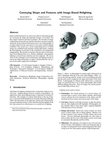
Copyright (c) 2003 Tom Talbotta)Copyright (c) 2003 Tom TalbottCopyright (c) 2003 Tom TalbottCopyright (c) 2003 Tom TalbottCopyright (c) 2003 Tom TalbottCopyright (c) 2003 Tom TalbottCopyright (c) 2003 Tom TalbottCopyright (c) 2003 Tom Talbottb)Copyright (c) 2003 Tom TalbottCopyright (c) 2003 Tom TalbottCopyright (c) 2003 Tom TalbottCopyright (c) 2003 Tom TalbottCopyright (c) 2003 Tom TalbottCopyright (c) 2003 Tom Talbottc)Figure 5: Above: Twelve photographs of the moon taken on consecutive nights during the waxing portion of the lunar cycle. Below, from leftto right: a) An unmodified photograph of a full moon. b) A set of control arrows used to define a field of incident lighting directions that lietangent to the moon’s surface across its breadth. c) The resulting composite photograph, which combines surface detail from the terminatorzones of each of the input photographs. The disk’s flat appearance results from the loss of large scale shading variation during composition.Source moon photographs c 2002-2003 Tom Talbott (http://www.blarg.net/ thomast/).to create alternating bands of light and dark oriented along lines ofzero curvature. Such bands have traditionally been used by illustrators to identify objects as metallic and to indicate their shape, sincethey mimic real-world anisotropic reflection effects [Gooch et al.1998].5Figure 6: Above: Three example images of a robotic assemblytaken under three different lighting directions (indicated by arrows).Below: An image composite produced with our system. The colored arrows indicate the predominant lighting direction used in selected regions of the composite. The first two were used to addhighlights to the cylindrical base, while the third was used to revealthe brushed texture of a flat surface. Not all photographs contributing to the composite are shown.appearance. The assembly’s specular surface presents a problemwith dynamic range; no single exposure setting can capture all ofits important features. To solve this problem, we supplemented ourdata set by taking photographs at two different exposures. Longerexposures revealed darker regions of the object, while shorter exposures avoided oversaturation in regions with bright specular highlights. We painted with photographs from both exposure sets whencreating the composite, using the interface to alternate between exposures as needed. We also used highlights from both exposure setsDiscussionOur goal has been to develop techniques that make it easy to createillustrations of complex objects that effectively communicate theirshape and texture using common lighting design techniques. Wehave presented an interactive tool that allows a user to relight objects by compositing a large number of photographs taken underdifferent lighting conditions. Our illustration system is the first ofits kind to suggest the idea of spatially varying the lighting acrossan image.While it is theoretically possible to produce images like ourswith traditional image compositing tools, it is infeasible in practice. Several of our features address this infeasibility and distinguish our application from compositing tools available in systemslike Adobe R Photoshop R : Image navigation: There are hundreds of source images inour skull and robotic assembly data sets; we provide the ability to use lighting direction to navigate them quickly. Painting many mattes simultaneously: The interpolatingbrush (Sec. 3.2.2) allows one to adjust several of the mattesat once and maintain smooth transitions in the composite between areas drawn from different input images. We used thisfeature heavily in the moon example. Renormalization: To avoid oversaturation when using somany additive blending operations, we enforce a normalization constraint across all the mattes for each pixel. Efficiency: In order to provide real-time feedback to the userduring painting, we take advantage of graphics hardware acceleration to perform the compositing operations quickly.
Our interface makes it possible to produce image compositeswith little time or effort. The skull and robotic assembly composites each took about 10 minutes to produce, and the moon about 45minutes. In all three cases, the “artist” was a CS graduate studentwithout any experience in art or illustration. Indeed, much of ourenthusiasm for this technique stems from the ease with which weobtained our results without possessing particular artistic skill.We think this approach to photographic illustration is promisingand suggests many directions for future work. While we suspectthat artists will always play some role in the illustration process, webelieve that parts of this process can be automated. Burt and Kolczynski [1993] have developed image fusion operators that combine different images (for example, different exposures) to form acomposite. Their methods could be applied to the problem of combining images under different illuminations. We could also providehigher-level interaction tools (e.g. a contrast brush) to make theartist’s job easier.Finally, it is becoming easy to collect a set of images using a“smart” camera. Can cameras be programmed to always collect auseful set of images? What is that useful set? And, can generalinteractive tools be built for processing those image sets?ReferencesA DAMS , A. 1999. Basic Techniques of Photography. Little Brown andCompany.A LTON , J. 1995. Painting with Light. University of California Press.A NDERSON , S., AND L EVOY, M. 2002. Unwrapping and visualizingcuneiform tablets. IEEE Computer Graphics and Applications Vol. 22,No. 6, 82–88.B URT, P. J., AND KOLCZYNSKI , R. J. 1993. Enhanced image capturethrough fusion. In Fourth Int. Conf. on Computer Vision, IEEE ComputerSociety, 173–182.C ALAHAN , S. 2000. Advanced RenderMan: Creating CGI for MotionPictures. Morgan Kaufman, A. A. Apodaca and L. Gritz Eds., 337–382.D EBEVEC , P., H AWKINS , T., T CHOU , C., D UIKER , H., S AROKIN , W.,AND S AGAR , M. 2000. Acquiring the reflectance field of a humanface. In Proceedings of SIGGRAPH 2000, ACM Press/Addison-WesleyPublishing Co., 145–156.D EBEVEC , P., W ENGER , A., T CHOU , C., G ARDNER , A., WAESE , J.,AND H AWKINS , T. 2002. A lighting reproduction approach to liveaction compositing. In Proceedings of SIGGRAPH 2002, ACM Press,547–556.D OBASHI , Y., K ANEDA , K., NAKASHIMA , E., YAMASHITA , H., ANDN ISHITA , T. 1995. A quick rendering method using basis functions forinteractive lighting design. Computer Graphics Forum, Vol. 14, No. 3,229–240.E PSTEIN , R., H ALLINAN , P., AND Y UILLE , A. 1995. 5 plus or minustwo eigenimages suffice: An empirical investigation of low-dimensionallighting models. In Proceedings of IEEE Workshop on Physics-basedModeling in Computer Vision, ACM Press, 108–116.G EORGHIADES , A., B ELHUMEUR , P. N., AND K RIEGMAN , D. 2001.From few to many: Illumination cone models for face recognition undervariable lighting and pose. In IEEE Transactions in Pattern Analysis andMachine Intelligence, Vol 23, No 6, 643–660.G OOCH , A., G OOCH , B., S HIRLEY, P., AND C OHEN , E. 1998. A nonphotorealistic lighting model for automatic technical illustration. In Proceedings of SIGGRAPH 1998, ACM Press, 447–452.H AMEL , J. 2000. A New Lighting Model for Computer Generated LineDrawings. PhD thesis, School of Computer Science, Otto-von-GuerickeUniversity of Magdeburg.H AWKINS , T., C OHEN , J., AND D EBEVEC , P. 2001. A photometric approach to digitizing cultural artifacts. In Proceedings of the 2001 conference on Virtual reality, archeology, and cultural heritage, ACM Press,333–342.H ODGES , E. 1989. The Guild Handbook of Scientific Illustration. JohnWiley and Sons, 89.K AUFMAN , J. E., AND C HRISTENSEN , J. F., Eds. 1984. IES LightingHandbook. Illuminating Engineering Society of North America.K AWAI , J. K., PAINTER , J. S., AND C OHEN , M. F. 1993. Radioptimization: goal based rendering. In Proceedings of SIGGRAPH 1993, ACMPress, 147–154.KOENDERINK , J. J., AND P ONT, S. C. 2002. Texture at the terminator. InProceedings of the First International Symposium on 3D Data Processing, Visualization and Transmission, 406–415.L ONDON , B., AND U PTON , J. 1997. Photography. Addison-Wesley.M ALZBENDER , T., G ELB , D., AND W OLTERS , H. 2001. Polynomialtexture maps. In Proceedings of SIGGRAPH 2001, ACM Press, 519–528.M ASSELUS , V., D UTR É , P., AND A NRYS , F. 2002. The free-form lightstage. In Eurographics Rendering Workshop, 247–256.M ILLERSON , G., Ed. 1991. Lighting for Television and Film. Focal Press.N IMEROFF , J. S., S IMONCELLI , E., AND D ORSEY, J. 1994. Efficient Rerendering of Naturally Illuminated Environments. In Fifth EurographicsWorkshop on Rendering, 359–373.P ELLACINI , F., T OLE , P., AND G REENBERG , D. P. 2002. A user interfacefor interactive cinematic shadow design. In Proceedings of SIGGRAPH2002, ACM Press, 563–566.P OULIN , P., AND F OURNIER , A. 1992. Lights from highlights and shadows. In Proceedings of the 1992 symposium on Interactive 3D graphics,ACM Press, 31–38.R AMAMOORTHI , R., AND H ANRAHAN , P. 2001. A signal-processingframework for inverse rendering. In Proceedings of SIGGRAPH 2001,ACM Press, 117–128.R AMAMOORTHI , R. 2002. Analytic PCA construction for theoretical analysis of lighting variability, including attached shadows, in a single imageof a convex lambertian object. In IEEE Transactions in Pattern Analysisand Machine Intelligence, 1322–1333.R ICK , J. W., AND W HITE , T. 1975. Photography of obsidian artifacts: Auseful alternative. Newsletter of Lithic Technology 4:29.S CHOENEMAN , C., D ORSEY, J., S MITS , B., A RVO , J., AND G REEN BURG , D. 1993. Painting with light. In Proceedings of SIGGRAPH1993, ACM Press, 143–146.S LOAN , P., M ARTIN , W., G OOCH , A., AND G OOCH , B. 2001. The litsphere: A model for capturing NPR shading from art. In Proceedings ofGraphics Interface 2001, B. Watson and J. W. Buchanan, Eds., 143–150.S LOAN , P., K AUTZ , J., AND S NYDER , J. 2002. Precomputed radiancetransfer for real-time rendering in dynamic, low-frequency lighting environments. In Proceedings of SIGGRAPH 2002, ACM Press, 527–536.S TROTHOTTE , T., AND S CHLECHTWEG , S. 2002. Non-P
the difcult traditional lighting-design problem for photography, or producing handmade illustrations. Our system allows users to quickly produce photographic illustrations with far less effort or artistic skill. 2 Related Work The goals and techniques of cinematic lighting design are discussed in detail